TronXY X5S Build Guide
This is a build guide and review for the awesome (and large) TronXY X5S I purchased from Banggood.com, but it is also available on GearBest.com.
Review
The build quality of this huge printer is reasonable given the price. The frame, heated bed, and motors are all great. Electronics are based on the Arduino-compatible Sanguino ATmega1284P processor. Drivers are the standard A4988. Electronics quality is reasonable and I’ve updated the config for Marlin 1.1.6; see the Firmware Update section on how to install this firmware update.
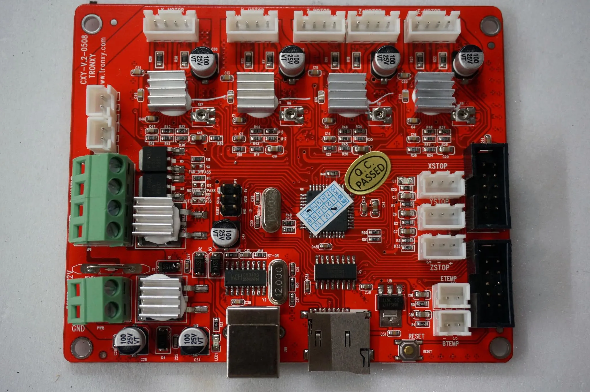
The layout is curiously similar to the Anet A8 control board.
You’ll definitely want to change the hot end to an all-metal version, since the max working time of the PTFE-lined extruder is at a wimpy 260°C. The large metal case around the hot end makes it extremely hard to service on a jam or clog. The default part cooling fan is weak, but it’s better than no fan at all.
Moreover, when printing at a reasonable 2800mm/min, I noticed that even PLA has trouble extruding. I believe this is due to the hot end having trouble holding its temperature. My fix for now is printing PLA at 210°C.
I plan to use a Titan-style extruder and pancake stepper motor, which is both lightweight and direct drive, with a Volcano heater block. My hope is to be able to do 100mm/sec with direct drive on PETG filament.
Unfortunately, the only UI element on the printer, the knob, is sticky for me… so definitely check this when installing the acrylic piece onto the LCD panel. Sand the acrylic hole bigger if necessary.
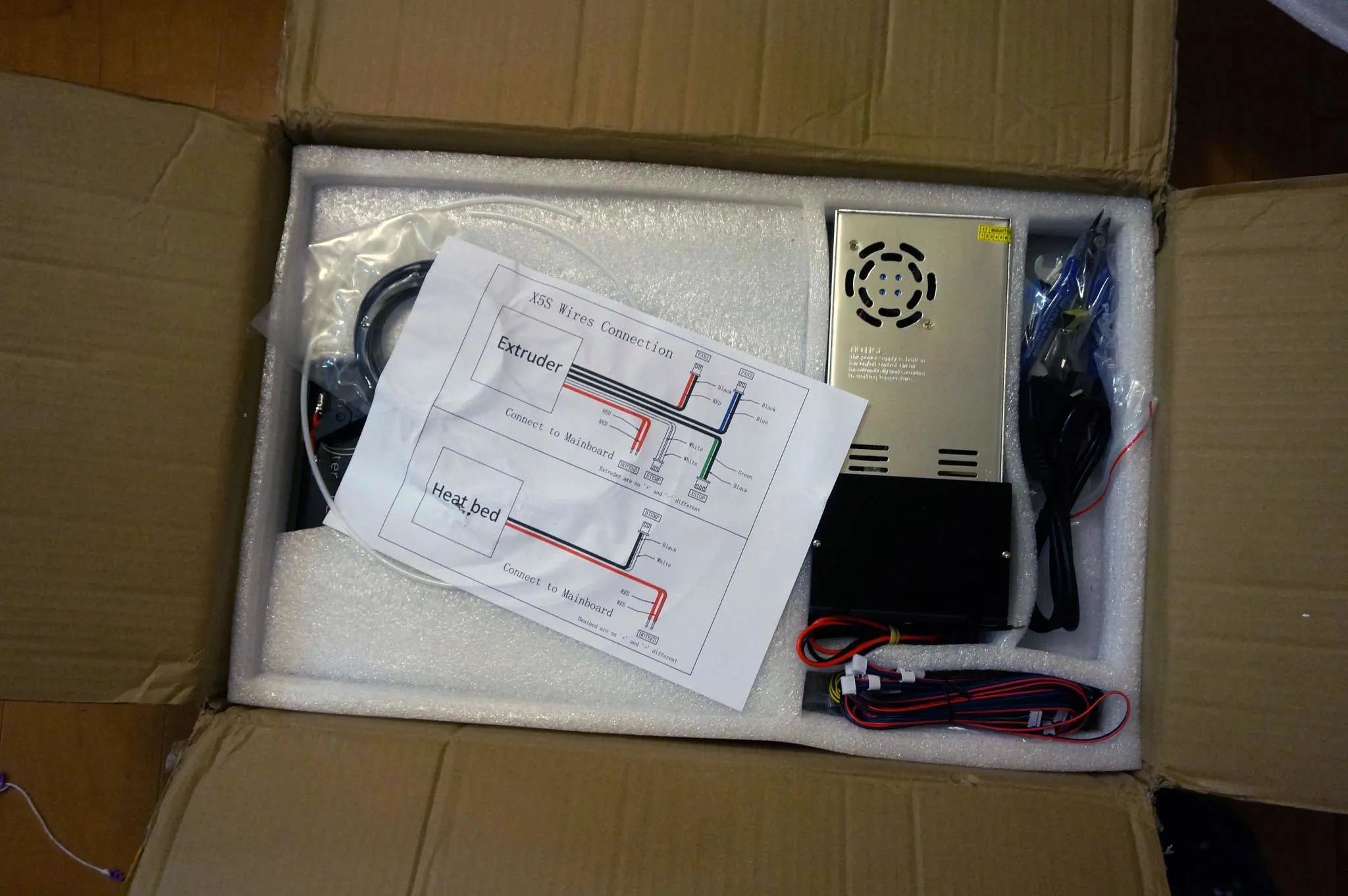
Unboxing
Packaging looks good. No damage on arrival.
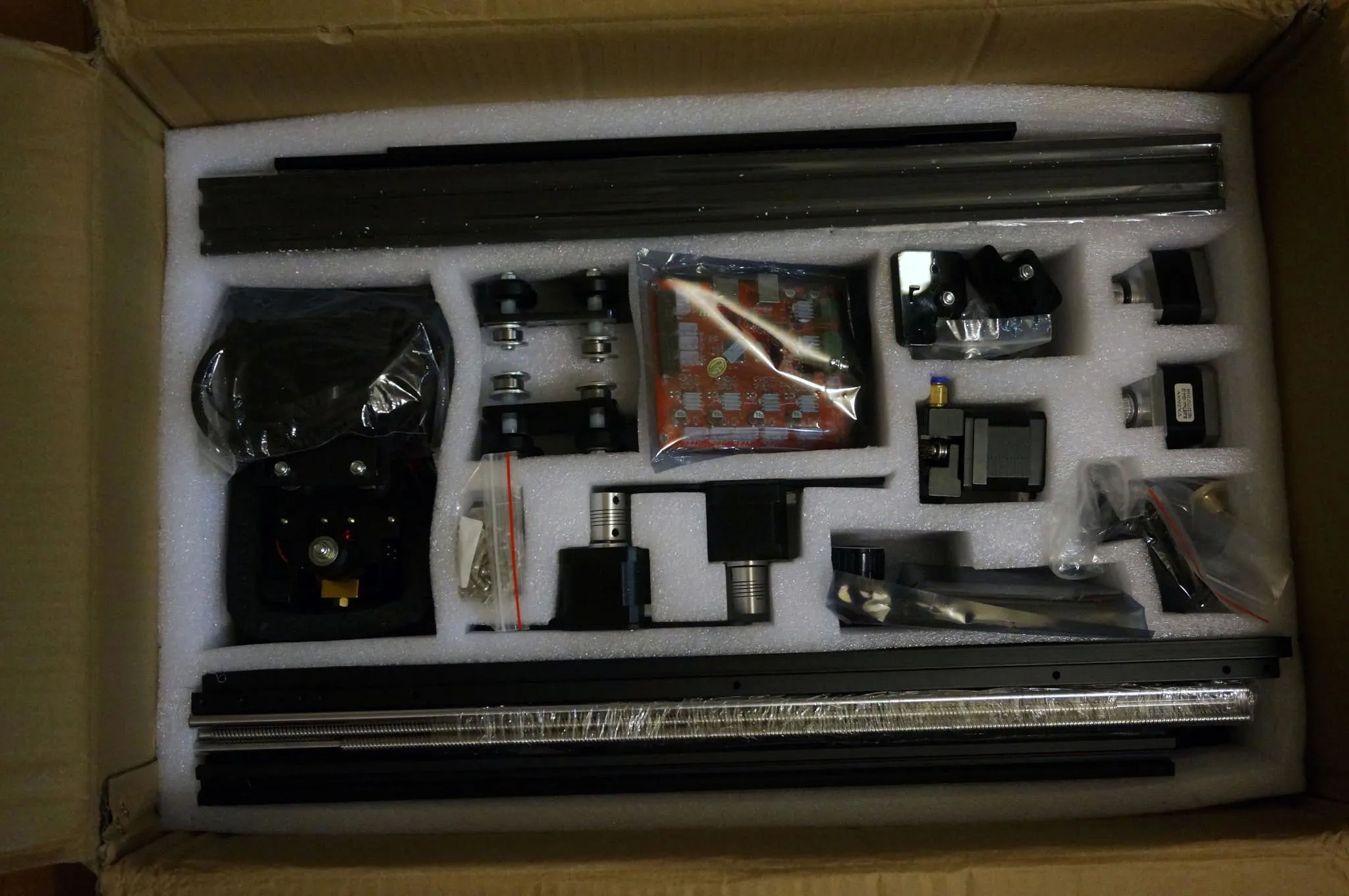
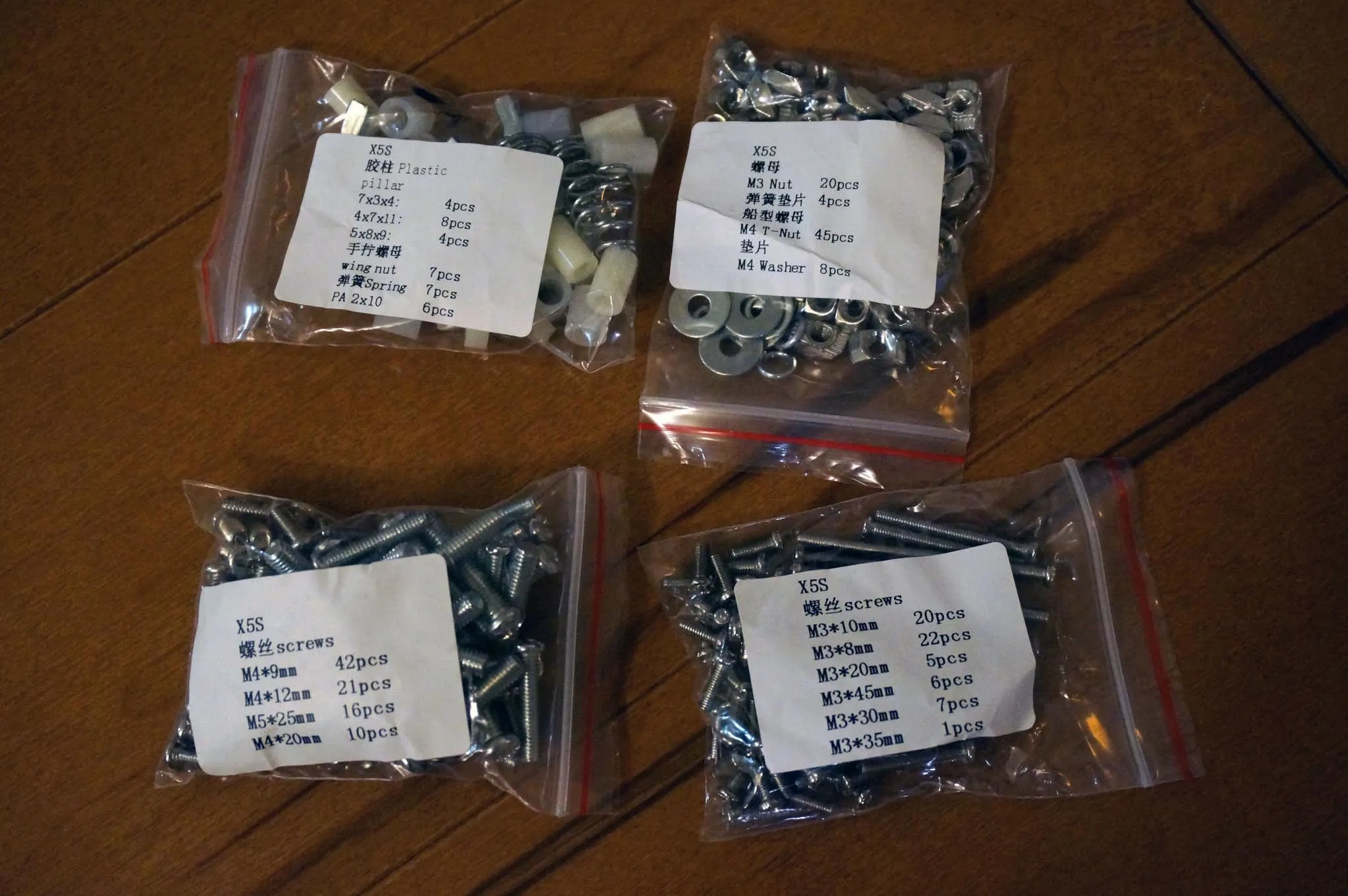
Hardware
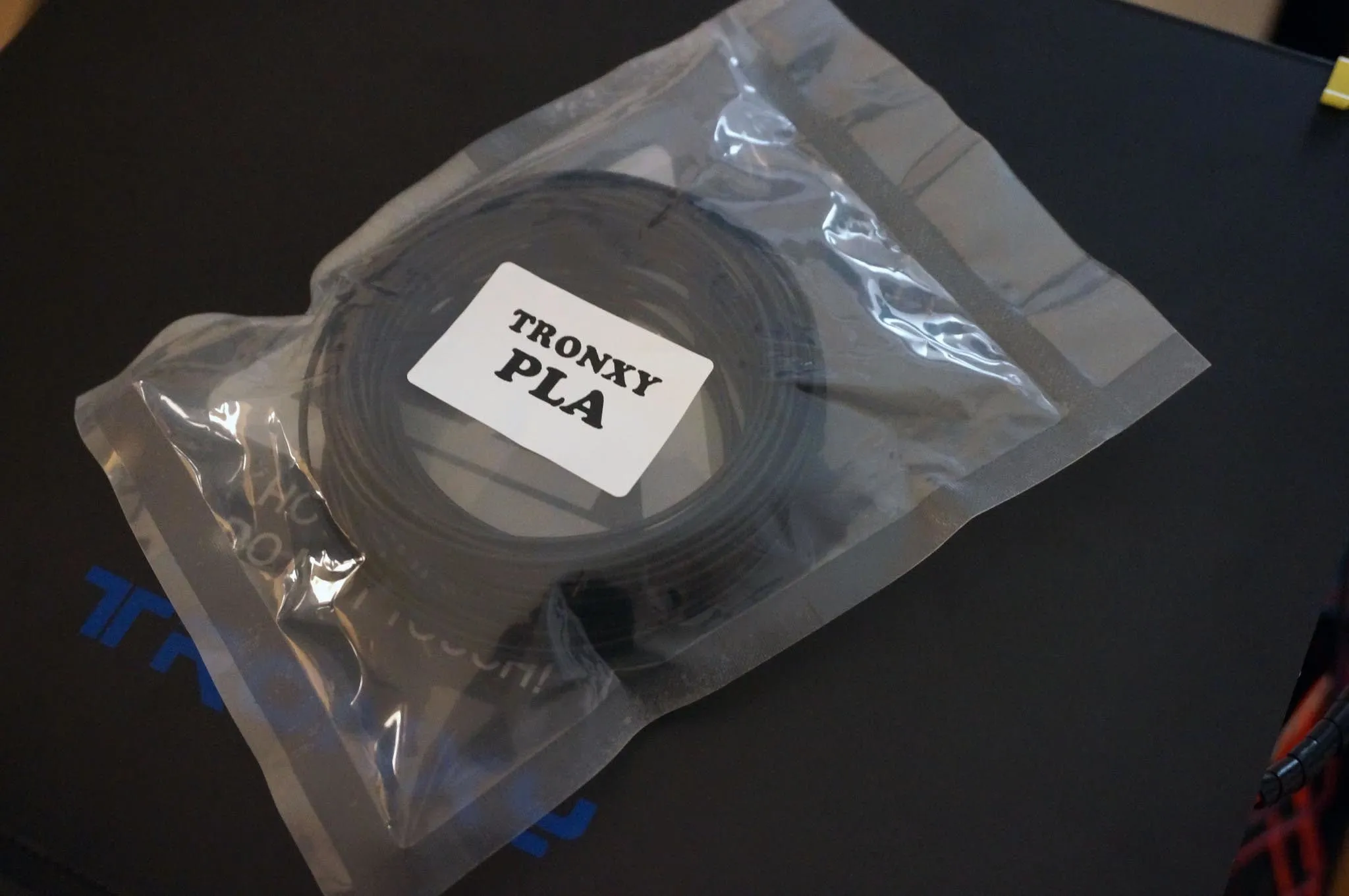
It even comes with a cute little PLA sample.
And some tools.
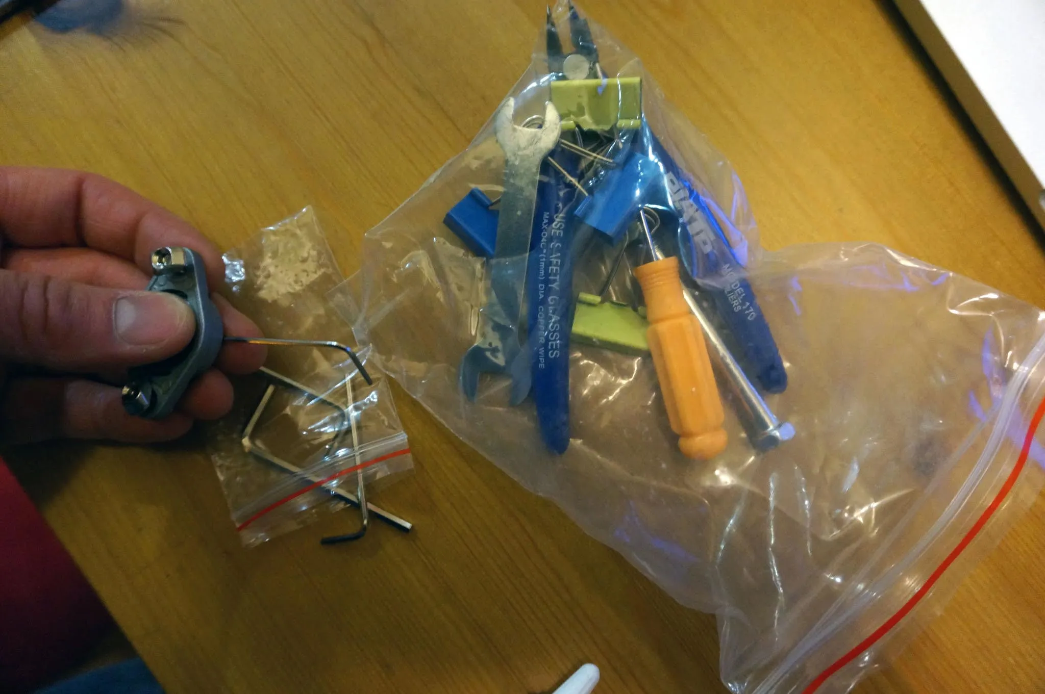
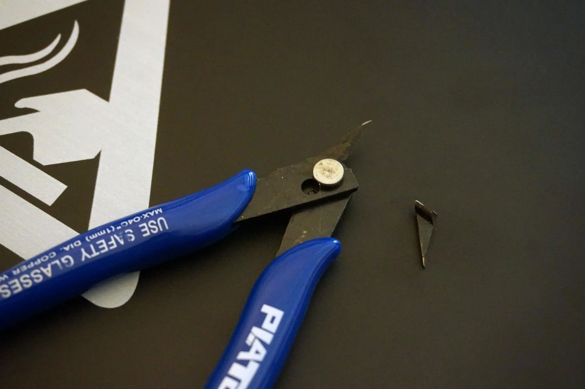
Be warned, the side cutters are DANGEROUS! They are cheap and will likely break off in your face! Don’t risk using them. Just throw them away.
Build
I’ll walk through the whole build including some details and corrections to the manual. If you want to check out the manual, here is a copy: https://www.dropbox.com/s/wi54xz2ijhnyv9n/Tronxy_X5S.pdf?dl=1.
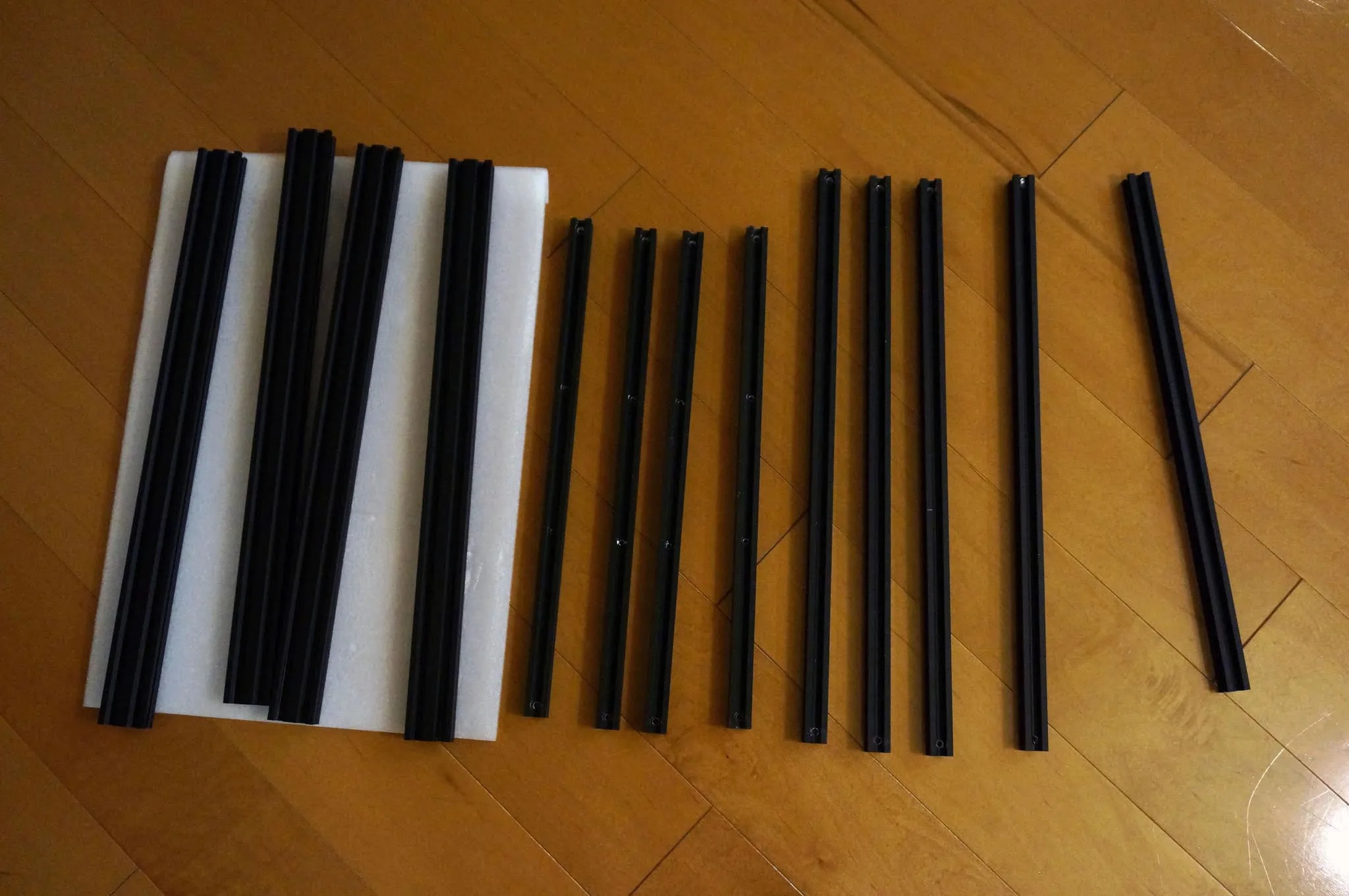
Lay out all the slotted beams.
Frame
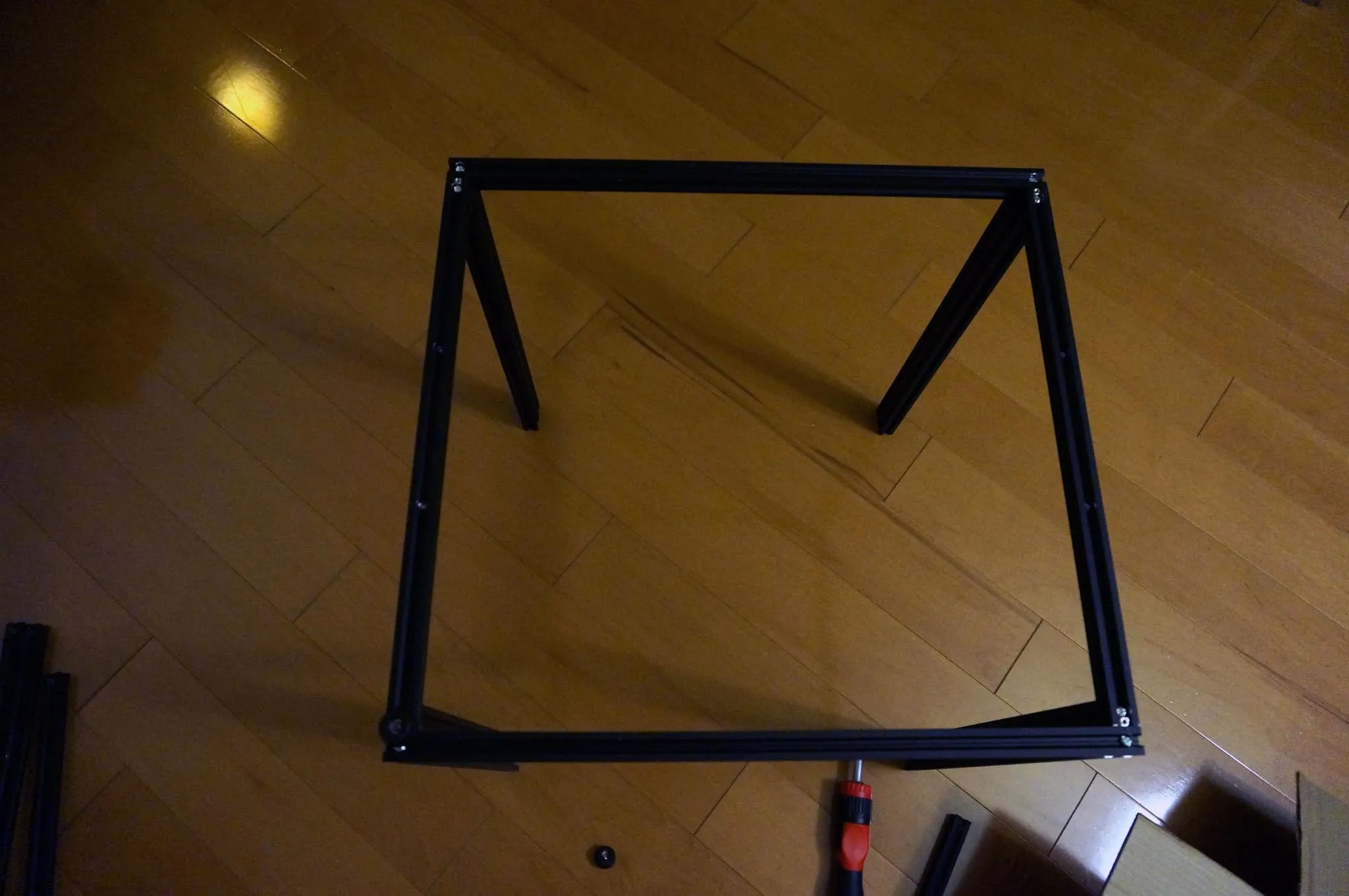
You’ll want to use the 4 double-thickness beams (they’ll be vertical) along with the 2 single-thickness beams with only 2 holes and 2 single-thickness beams with 4 holes.
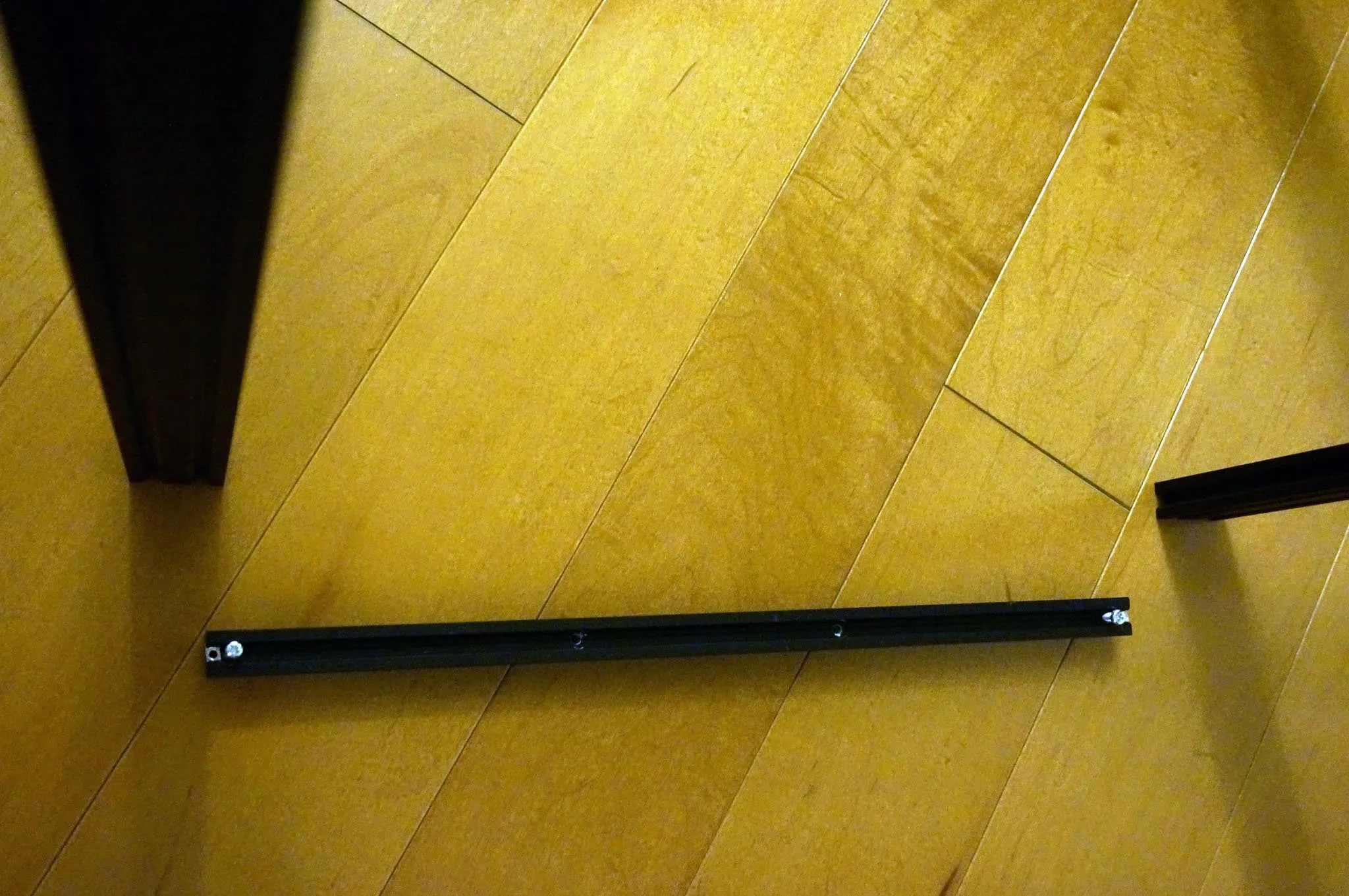
The shorter beams with 4 holes run parallel to the thicker side of the vertical beams… like this:
Find these bits of hardware:
8x 5mm x 25mm bolt
4x 4mm x 8mm bolt
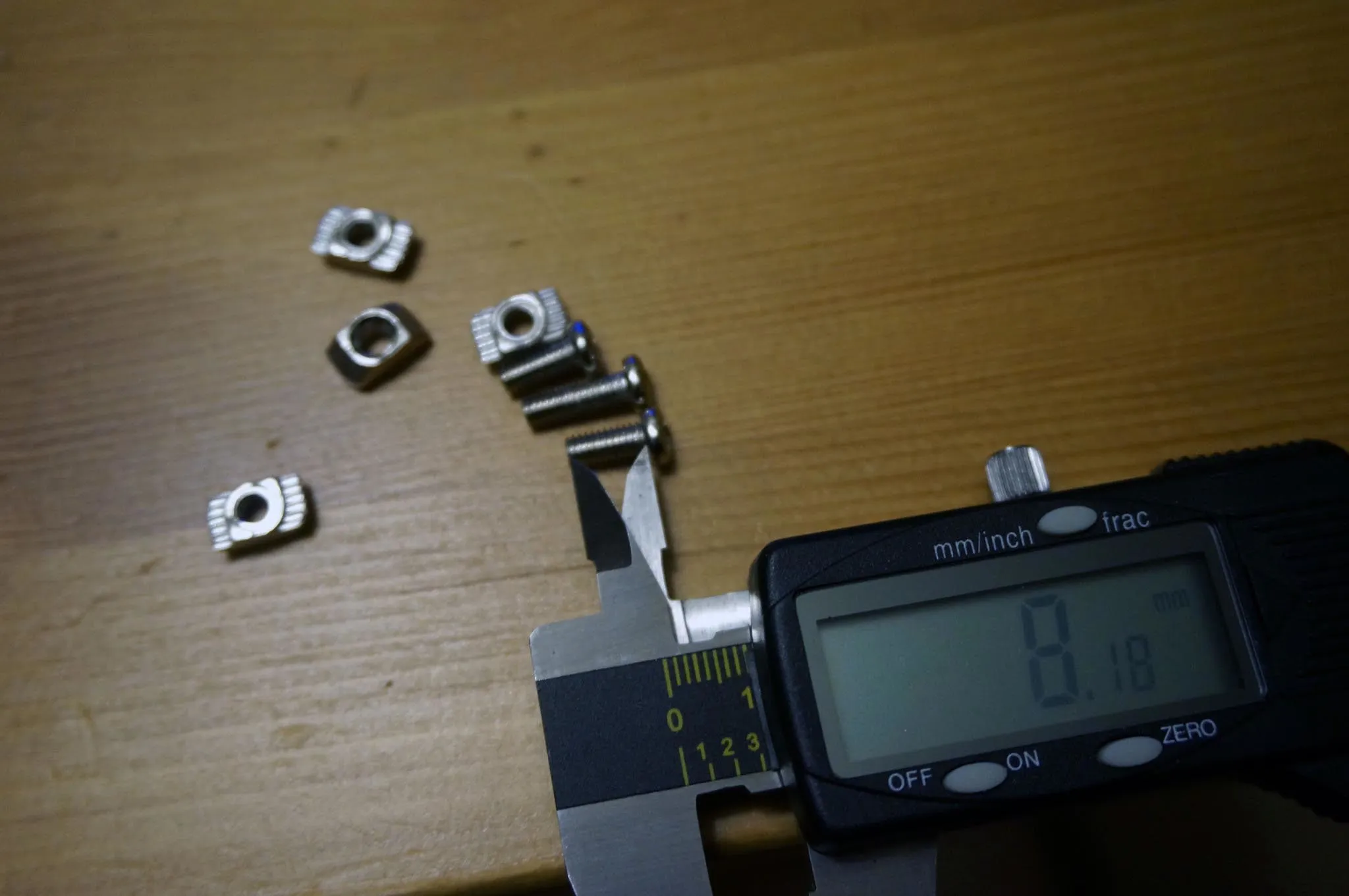
4x T-nuts
4x 4mm washer
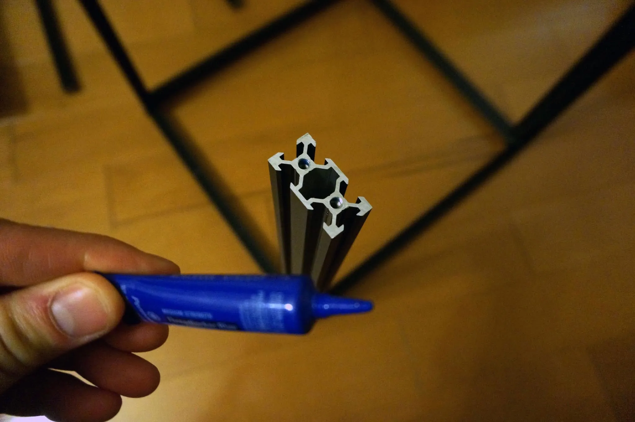
4x rubber footI used blue thread lock to make sure any movement from the machine will not loosen the bolts.
I assembled the longer ends first.
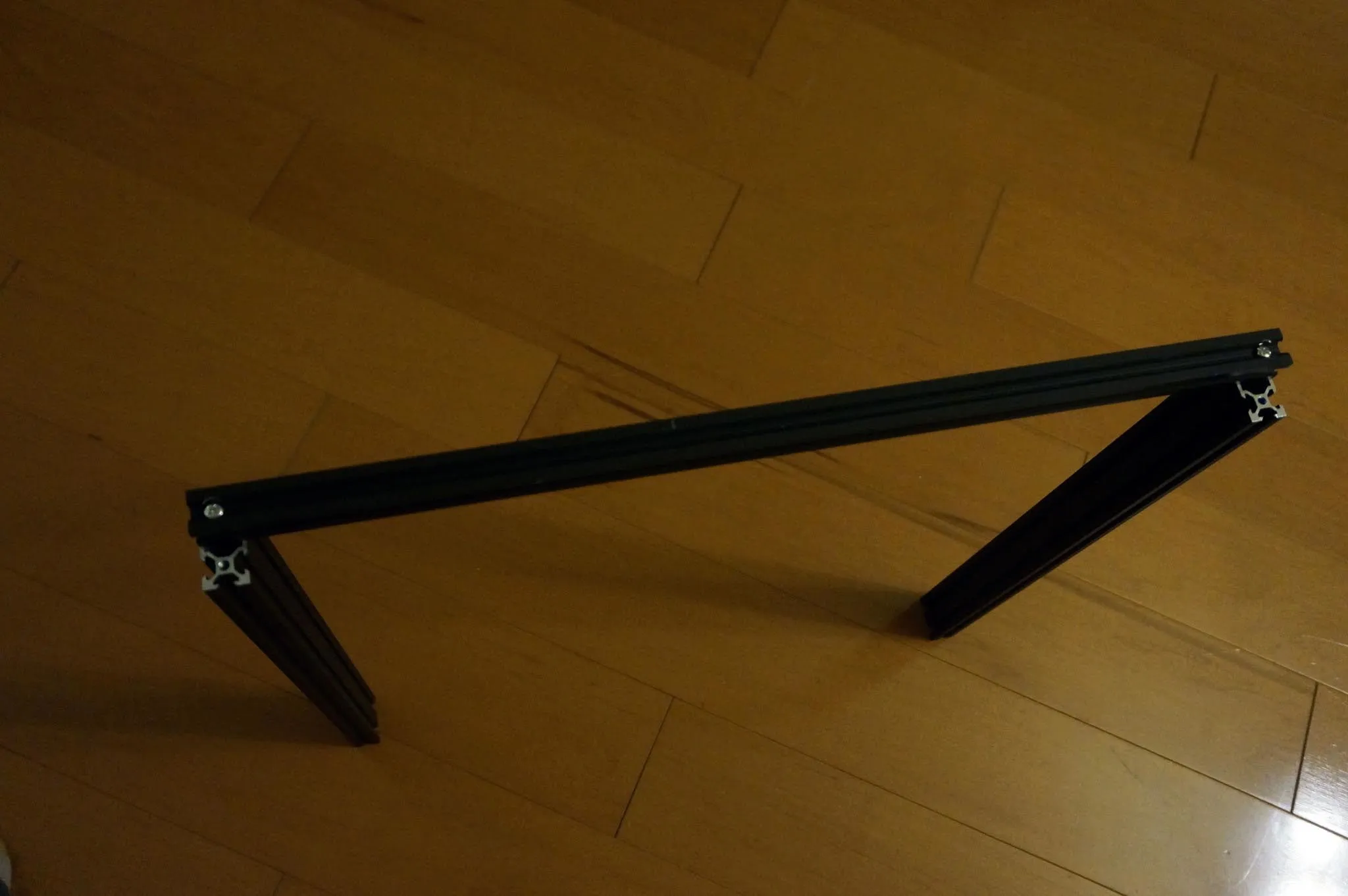
Be sure to insert the T-nuts into the ends of the shorter beams before bolting down.
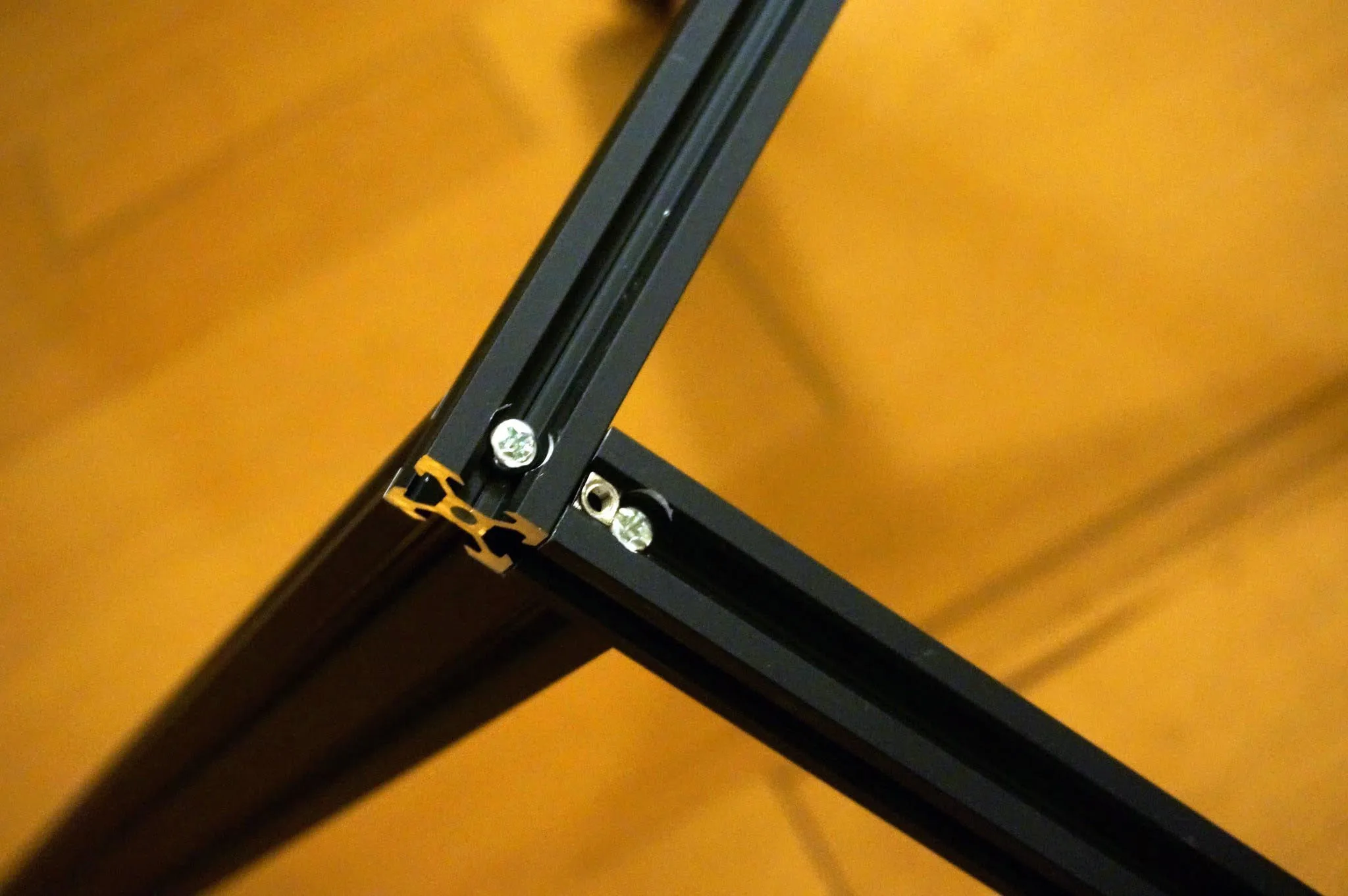
Attach the rubber feet by screwing the small bolt through the washer and rubber foot into the T-nut.
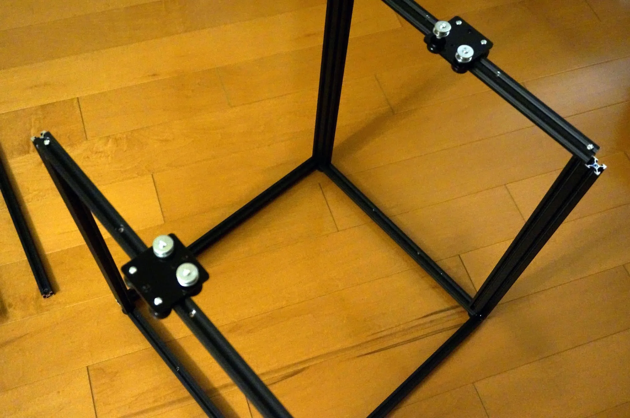
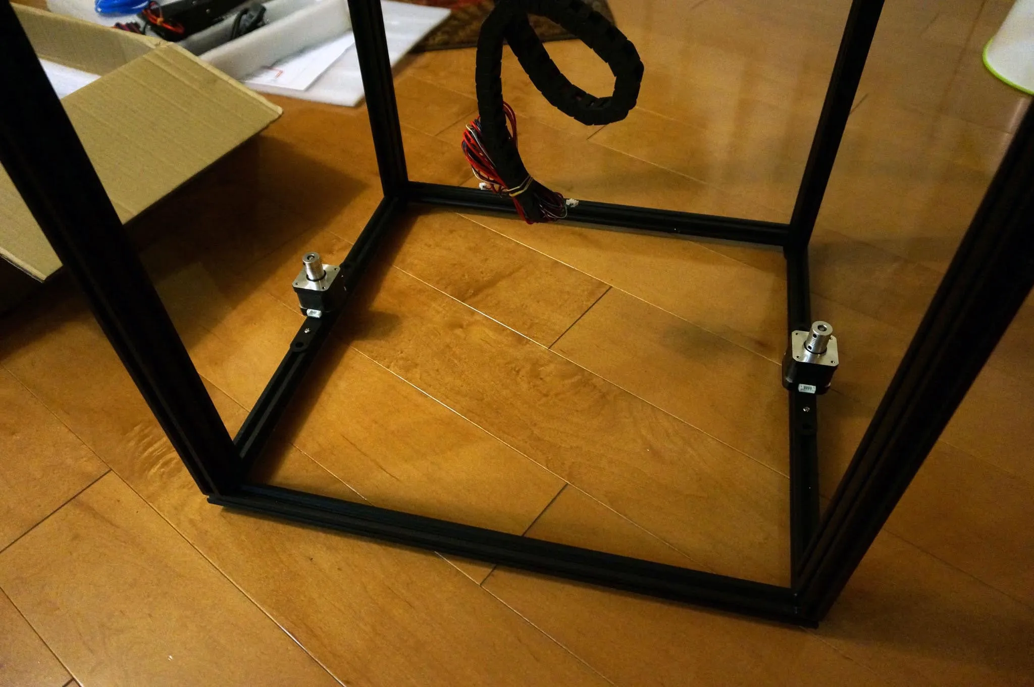
Find 8 more 5mm x 25mm bolts, the y-axis carriage mounts, and attach them. My mounts were different from the manual and erroneously both labeled “R”. It’s cool though, just mount them like this:
Measure diagonally across both the top and bottom to true up the cuboid that will soon be your printer.

Tighten down the screws in the corners once everything is square.
X and Y Carriage
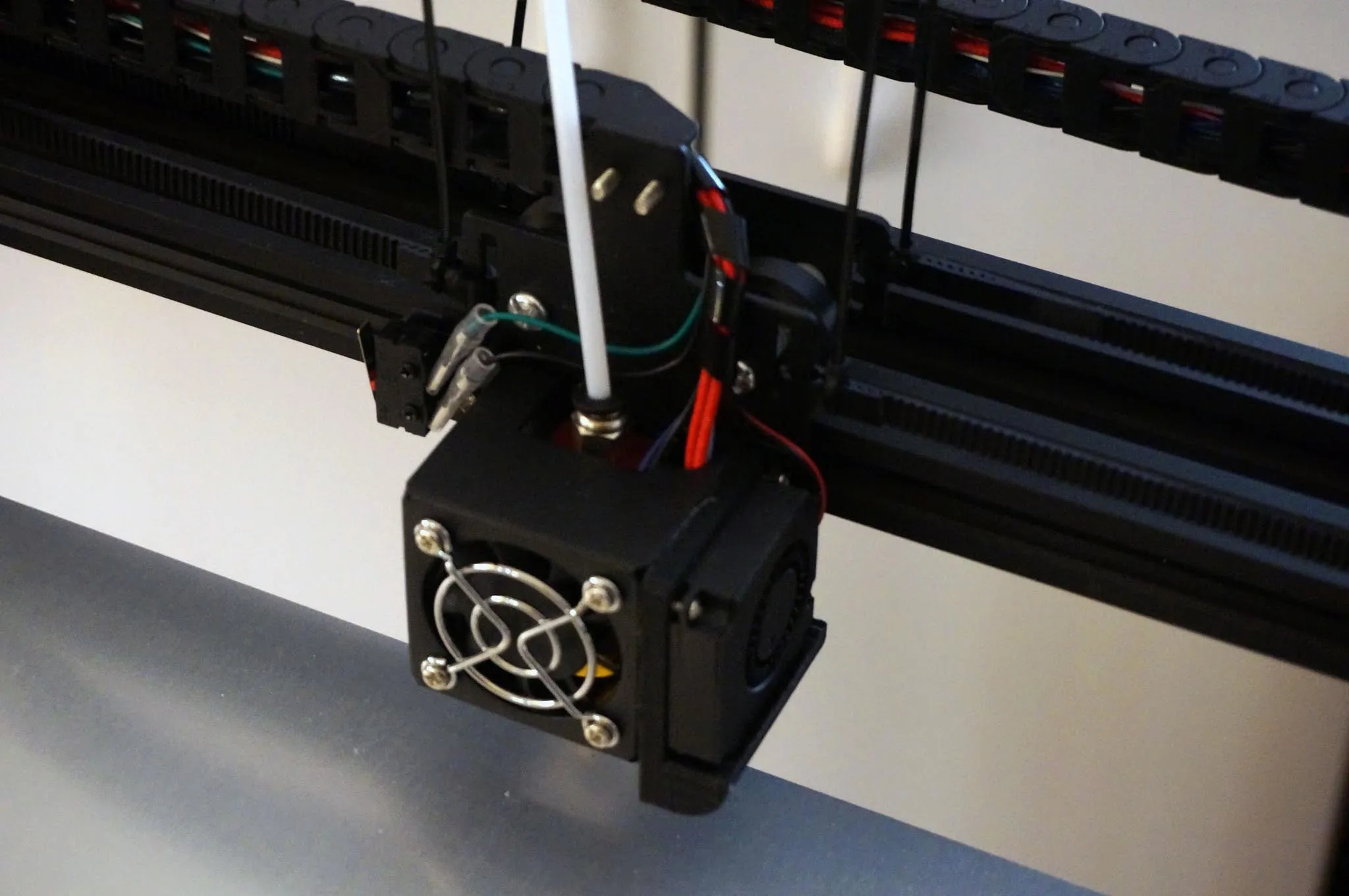
Find the hot end, the last slotted aluminum bar, and 4x 4mm x 8mm bolts.
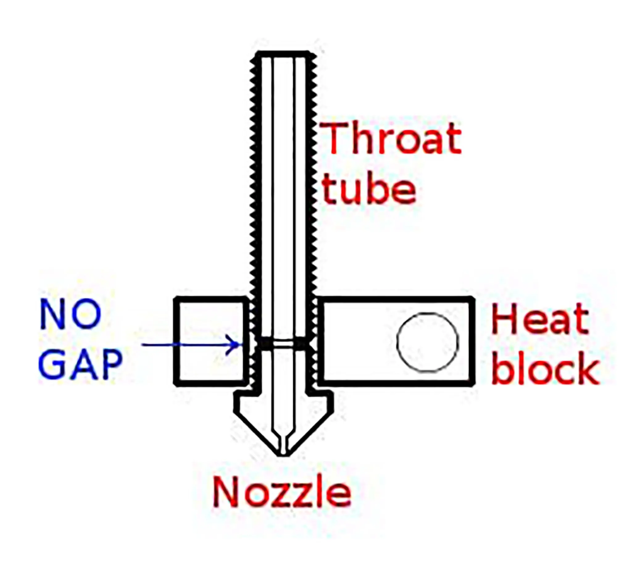
Before installing the hot end and carriage onto the rail, check that the hot end is properly assembled. Mine was not. Dan has a great guide about this on his blog. This article boils down to the fact that we want to make sure there is no gap between the throat and the nozzle. The following photo is from his blog.
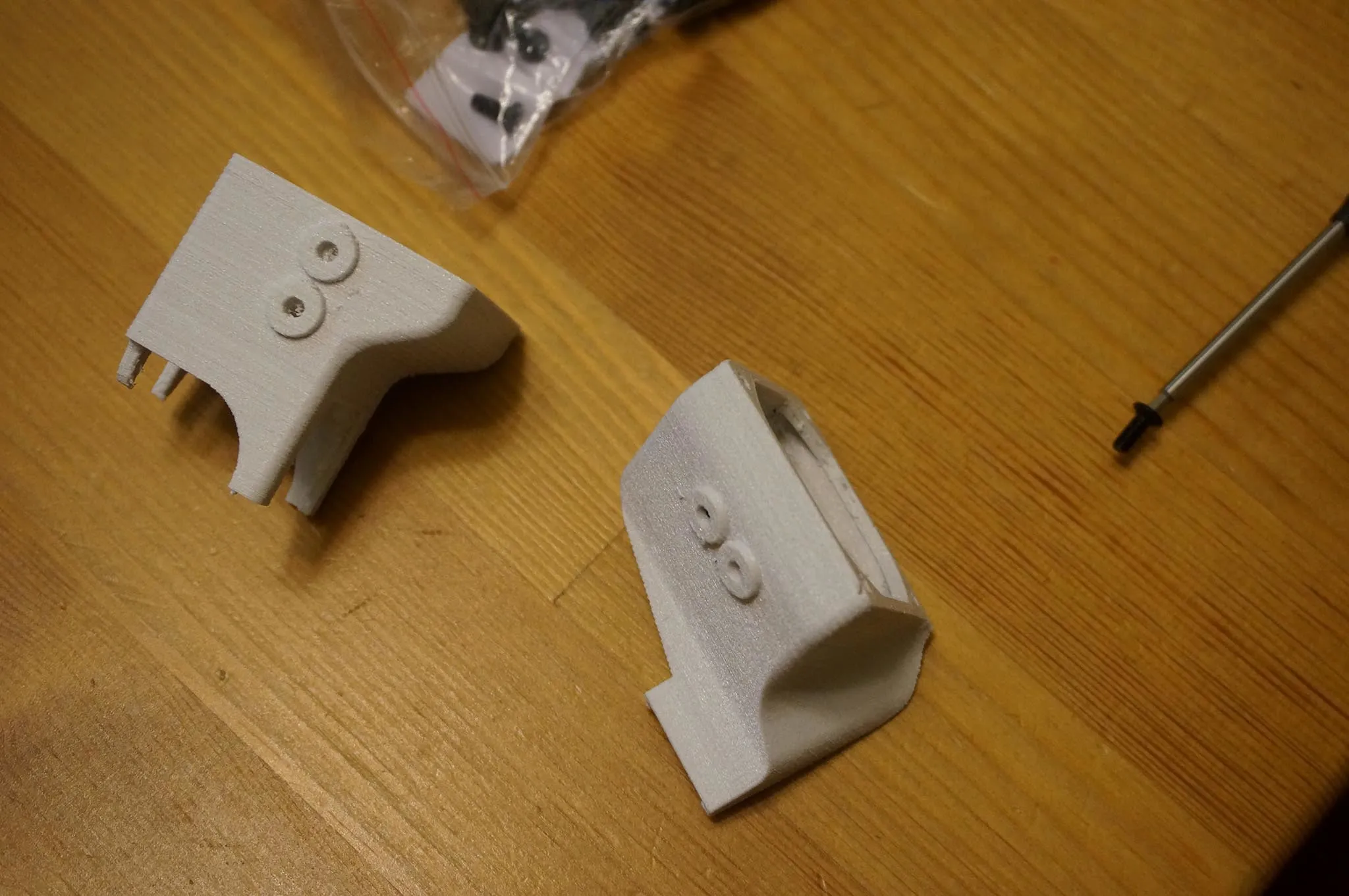
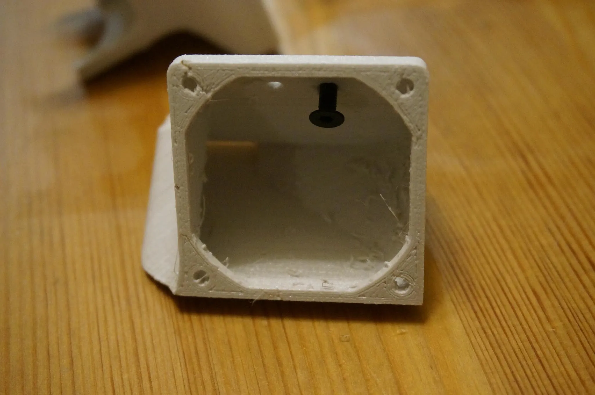
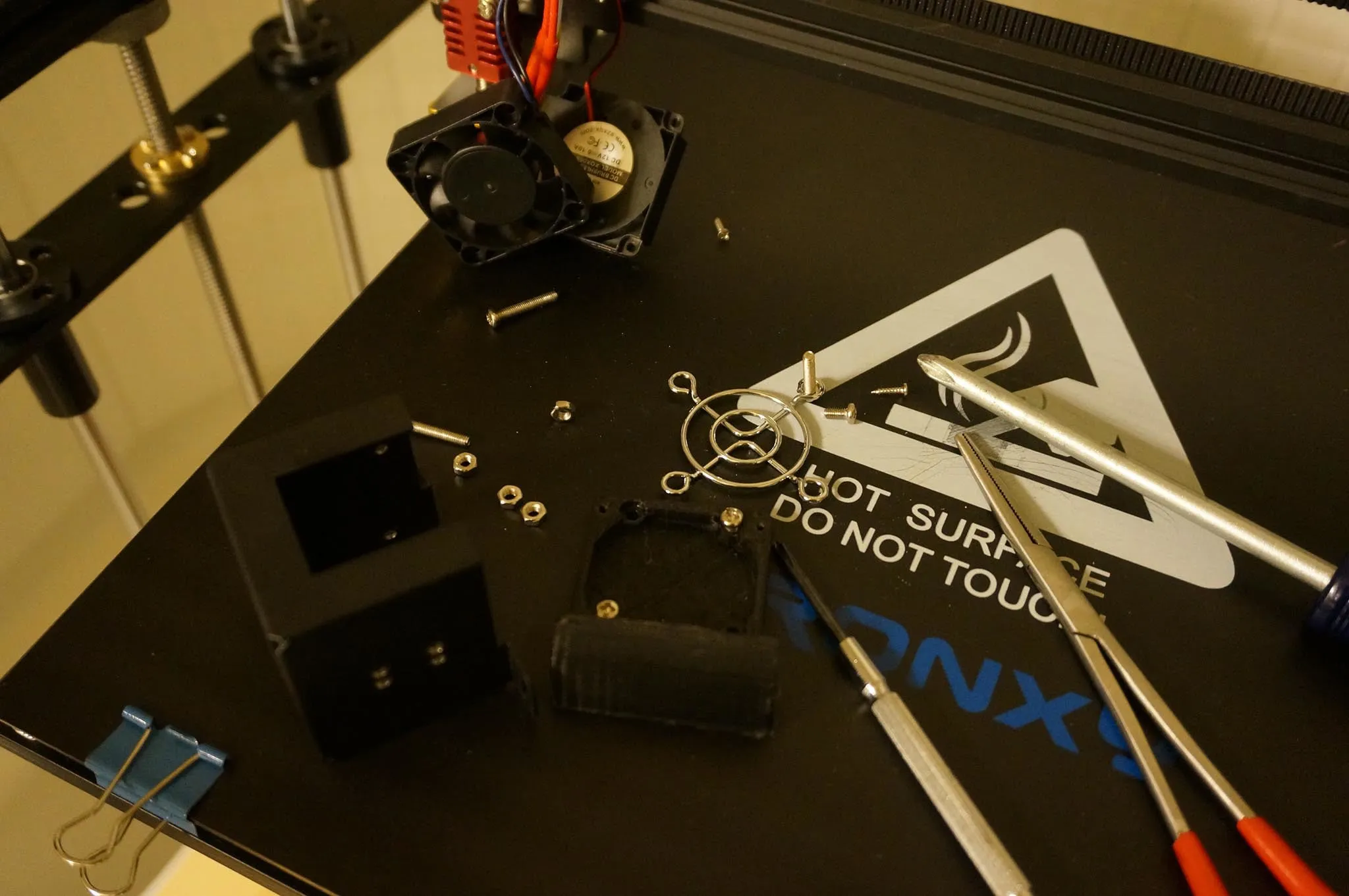
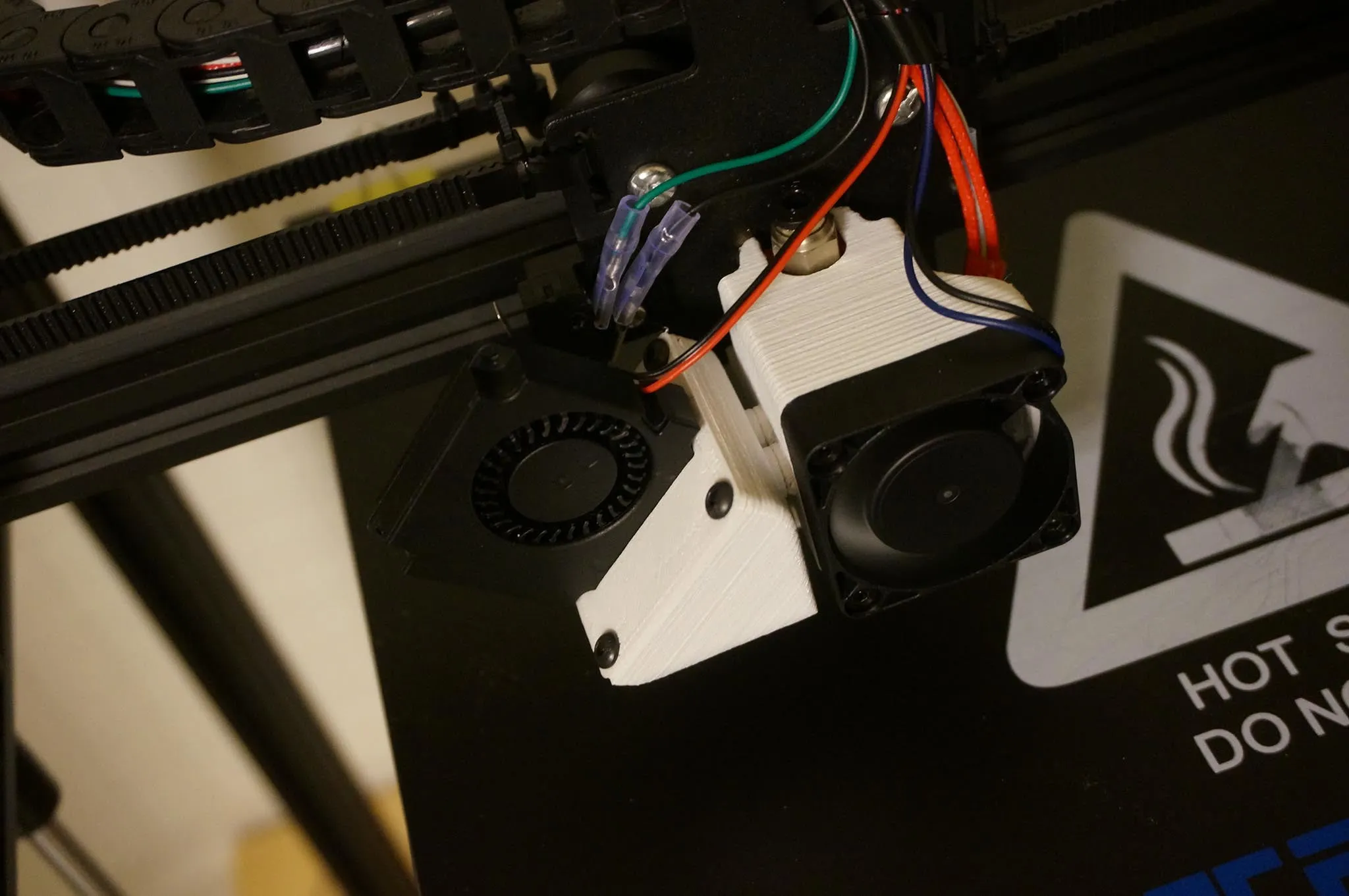
This would be a good time to change the cooling block. If you have another printer, I suggest printing this cooling system and installing it now: https://www.thingiverse.com/thing:2706922. You’ll also need this adapter plate if the included fan is a blower type: https://www.thingiverse.com/thing:2765424. The standard shroud will work OK as well, but is much less convenient, as the metal case covers the entire hot end. So, you can print one once you get your first printer set up!
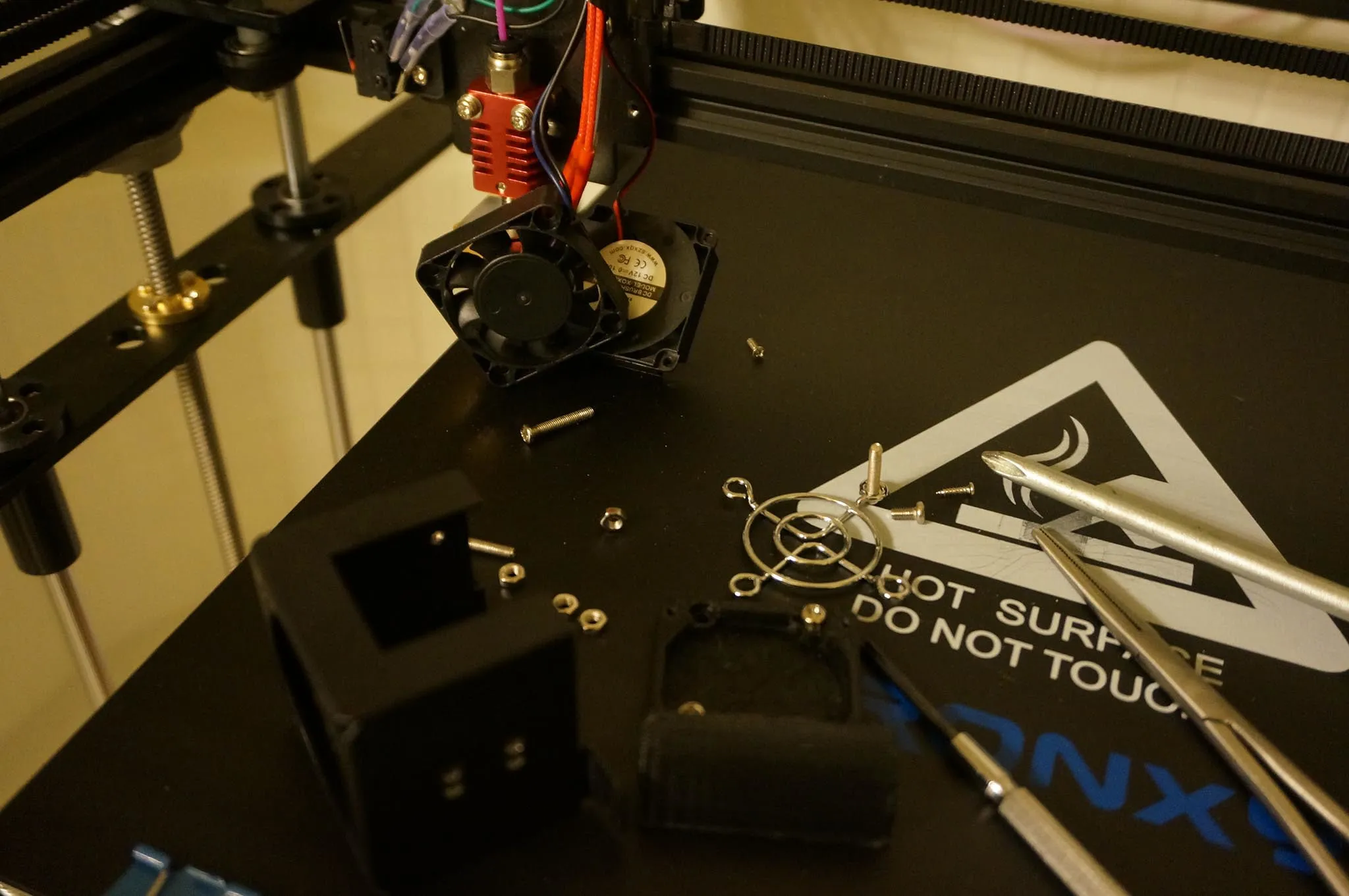
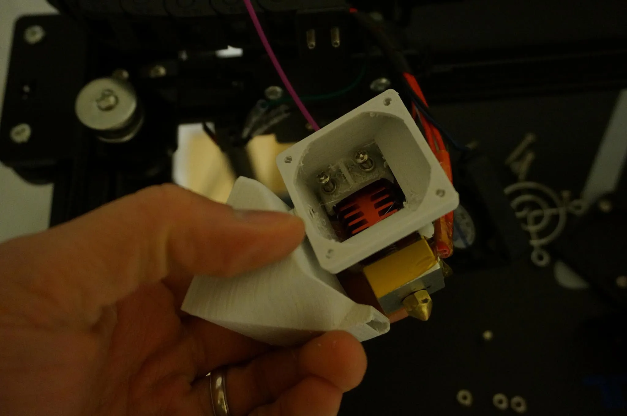
You can be fairly certain that if your nozzle is screwed all the way into the heating block (no visible threads on the brass nozzle), there is a gap. Notice in this photo that there is no gap between the nozzle and heater, so there is probably a gap between the throat and the nozzle.
You’ll want to unscrew the nozzle and screw the throat down into the heating block a bit more.
With the nozzle removed, I put the PTFE tube down into the throat, all the way to the heating block, then marked it with a sharpie so I know how far the PTFE tube should be inserted when properly installed (the end of the PTFE should meet the brass nozzle).
Install the nozzle, tighten, then be sure to tighten again after heating up to ~240 degrees (once the printer is assembled).
Now, on with the assembly.
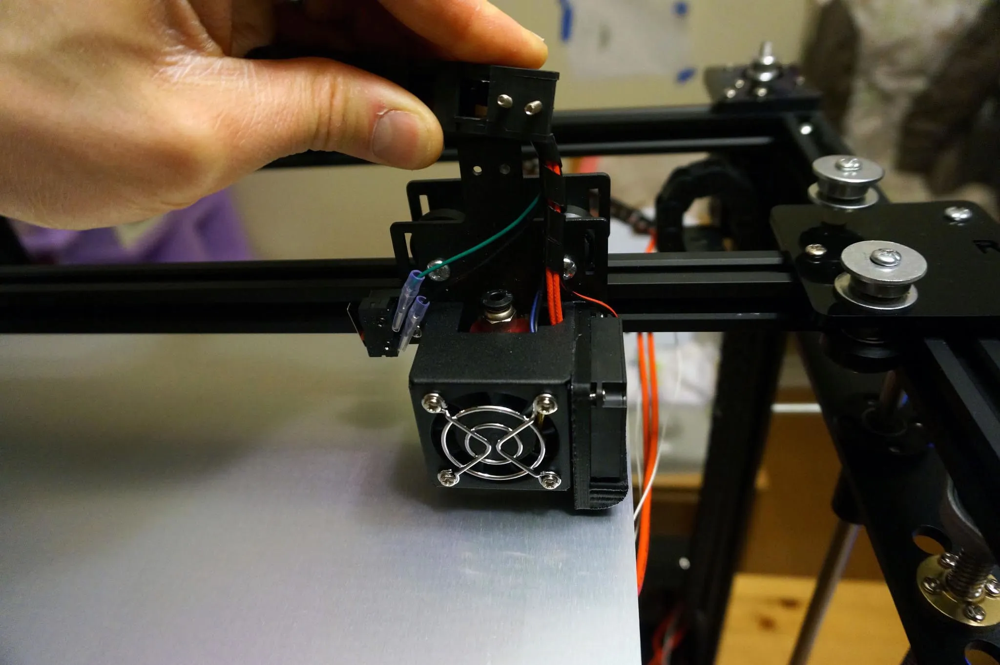
Install the carriage while ensuring not to over-tighten any parts that attach to acrylic, which could crack the part. Also, avoid letting any thread lock touch the acrylic, which will make the acrylic much more brittle.
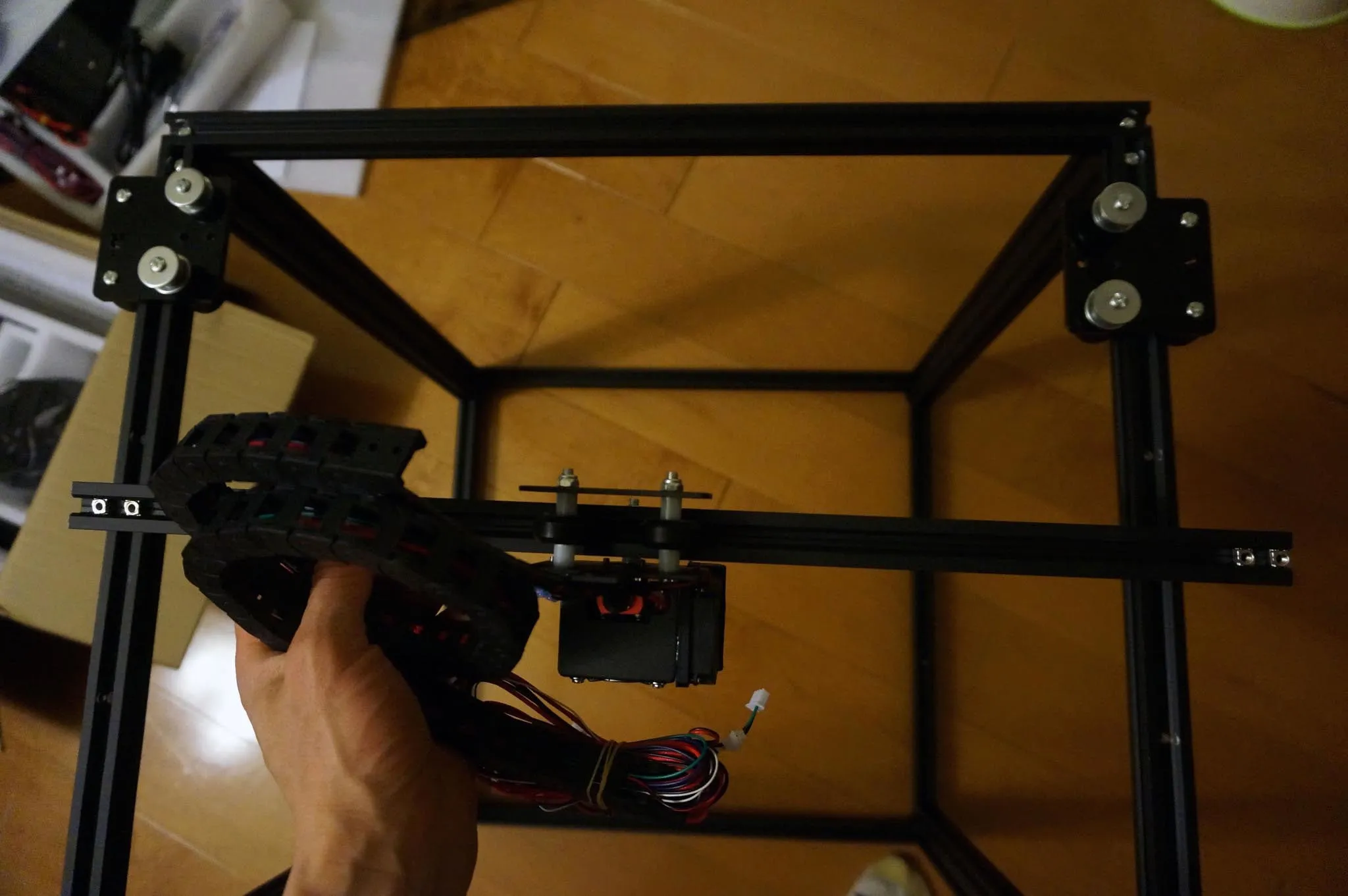
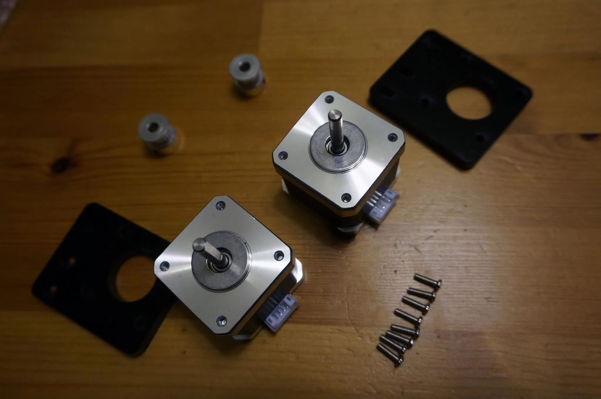
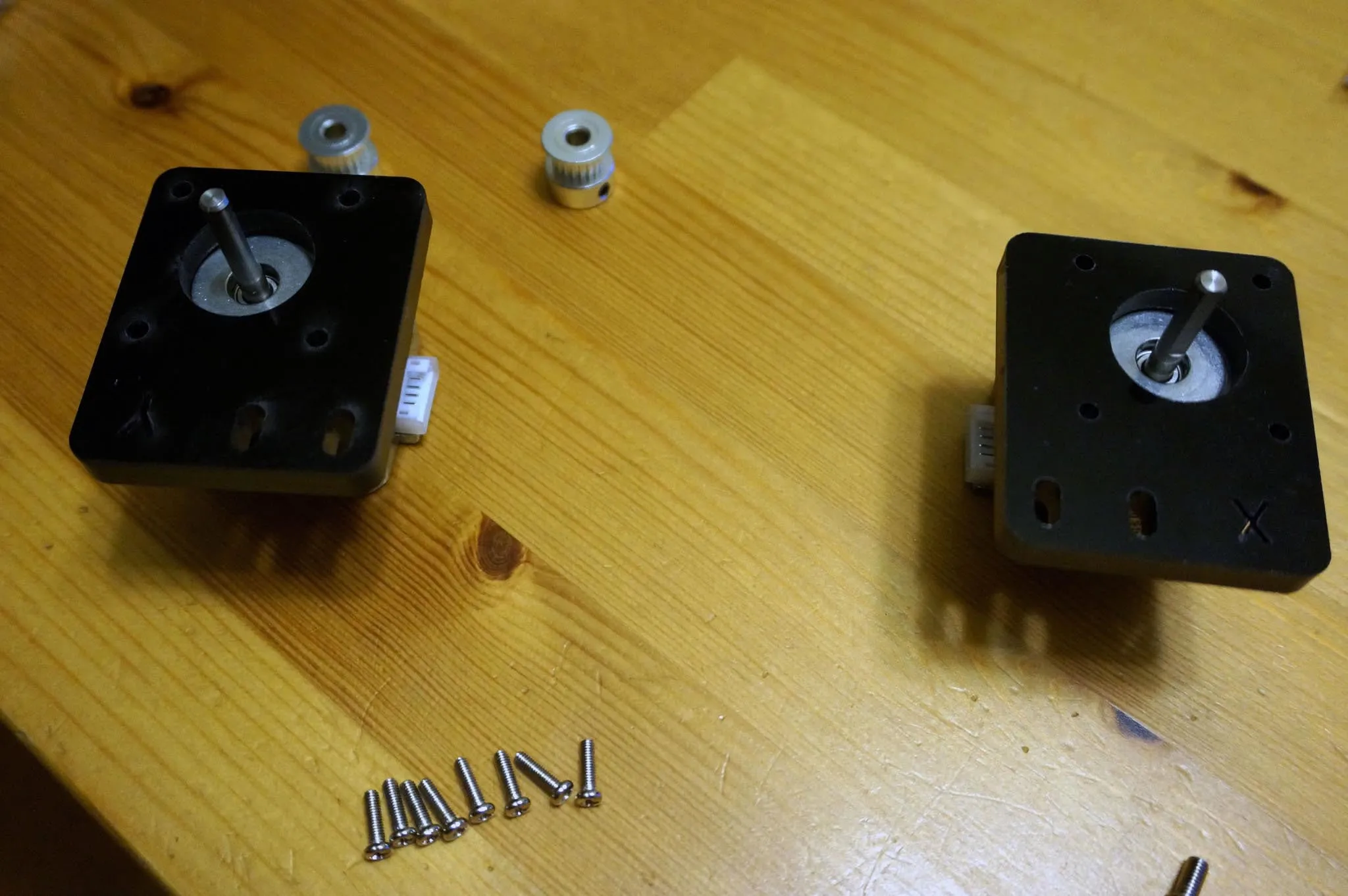
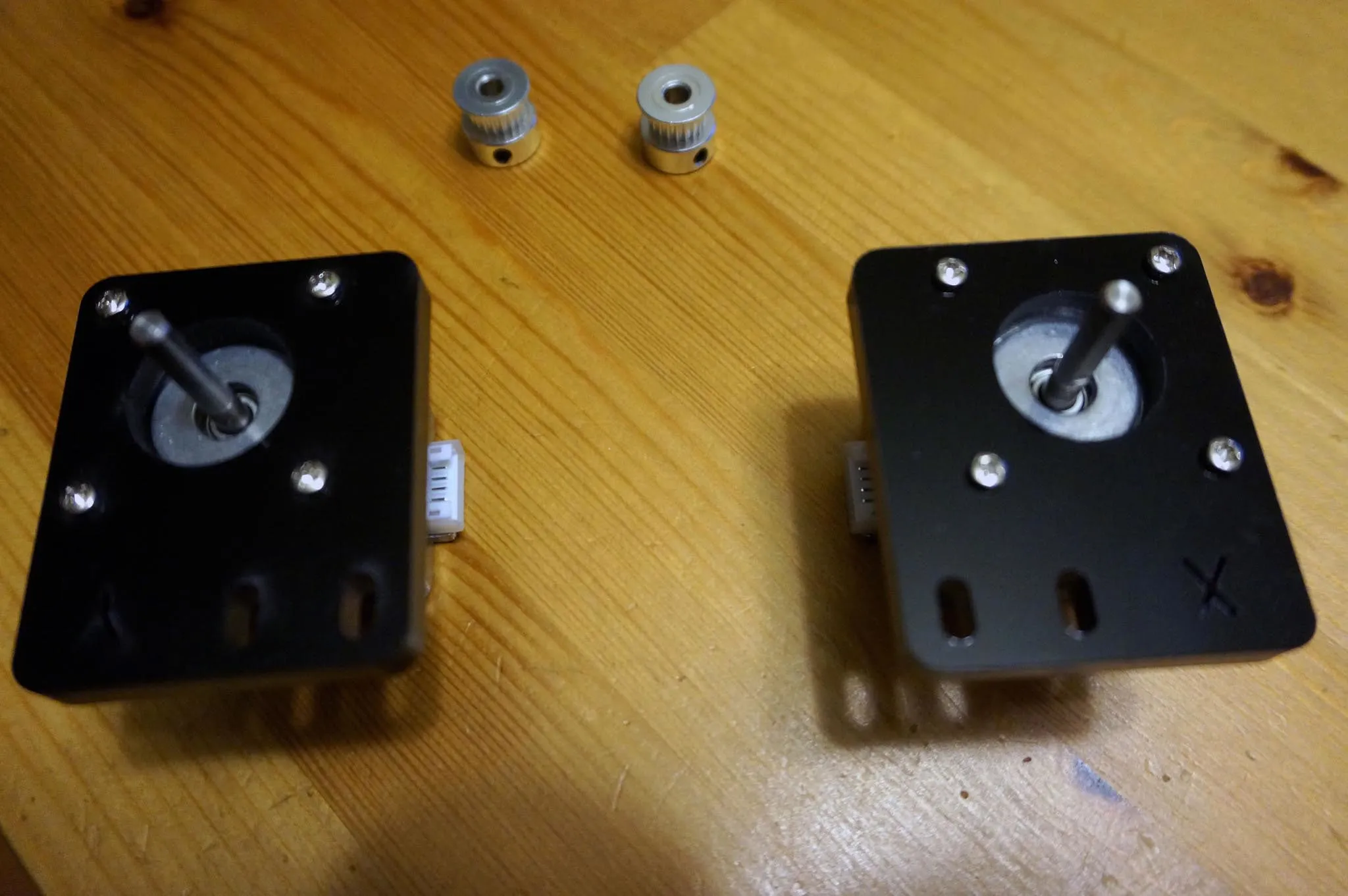
X and Y Motors
Assemble the X and Y motor carriers using 3mm x 8mm screws and the T-nuts.
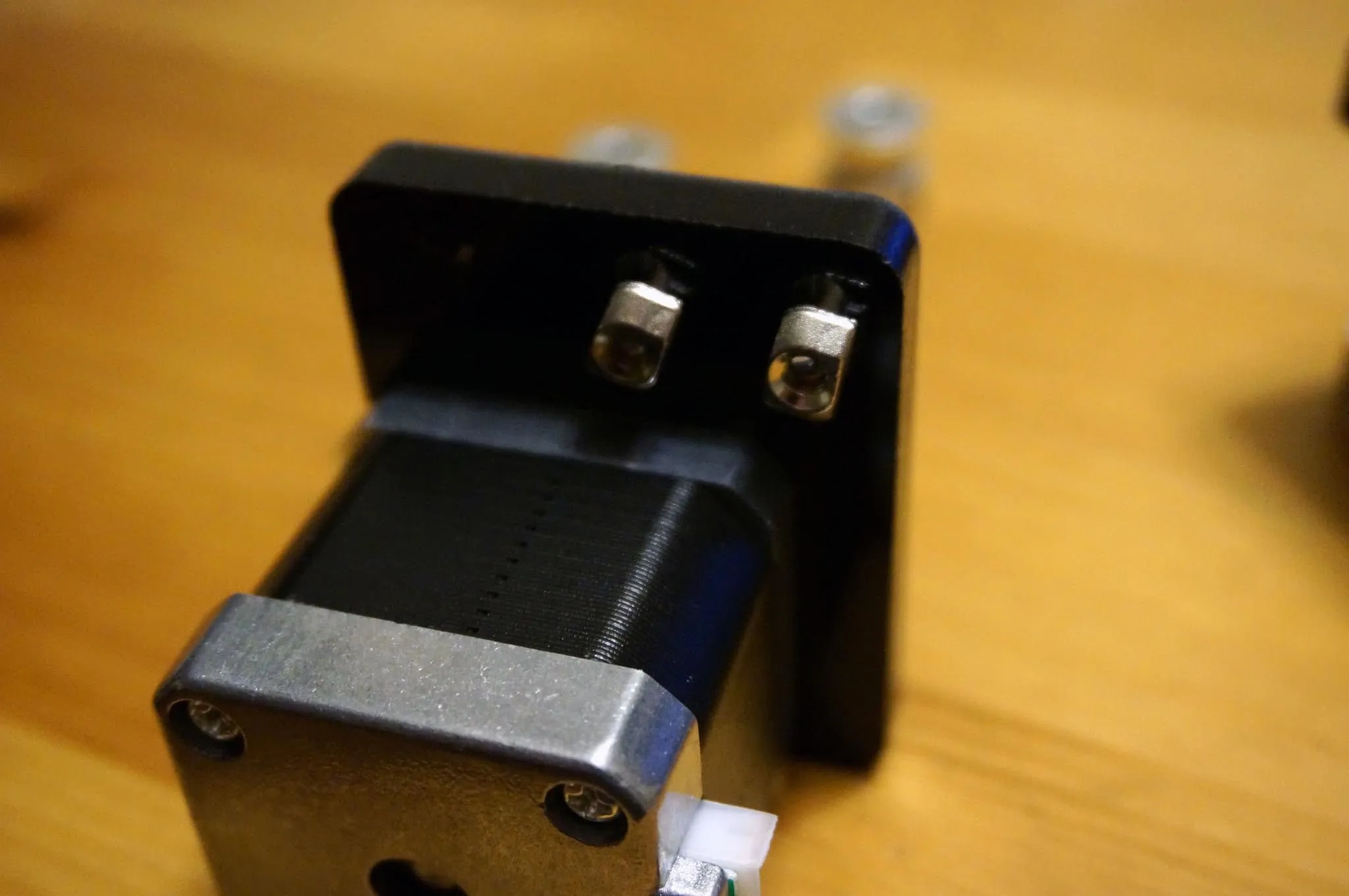
Affix these to the frame with 4 T-nuts and 4mm x 10mm bolts. The overhanging bit of acrylic goes towards the center. One way to use the T-nuts is to put them on the bolts and then insert the whole assembly and tighten. The T-nuts will rotate into place.
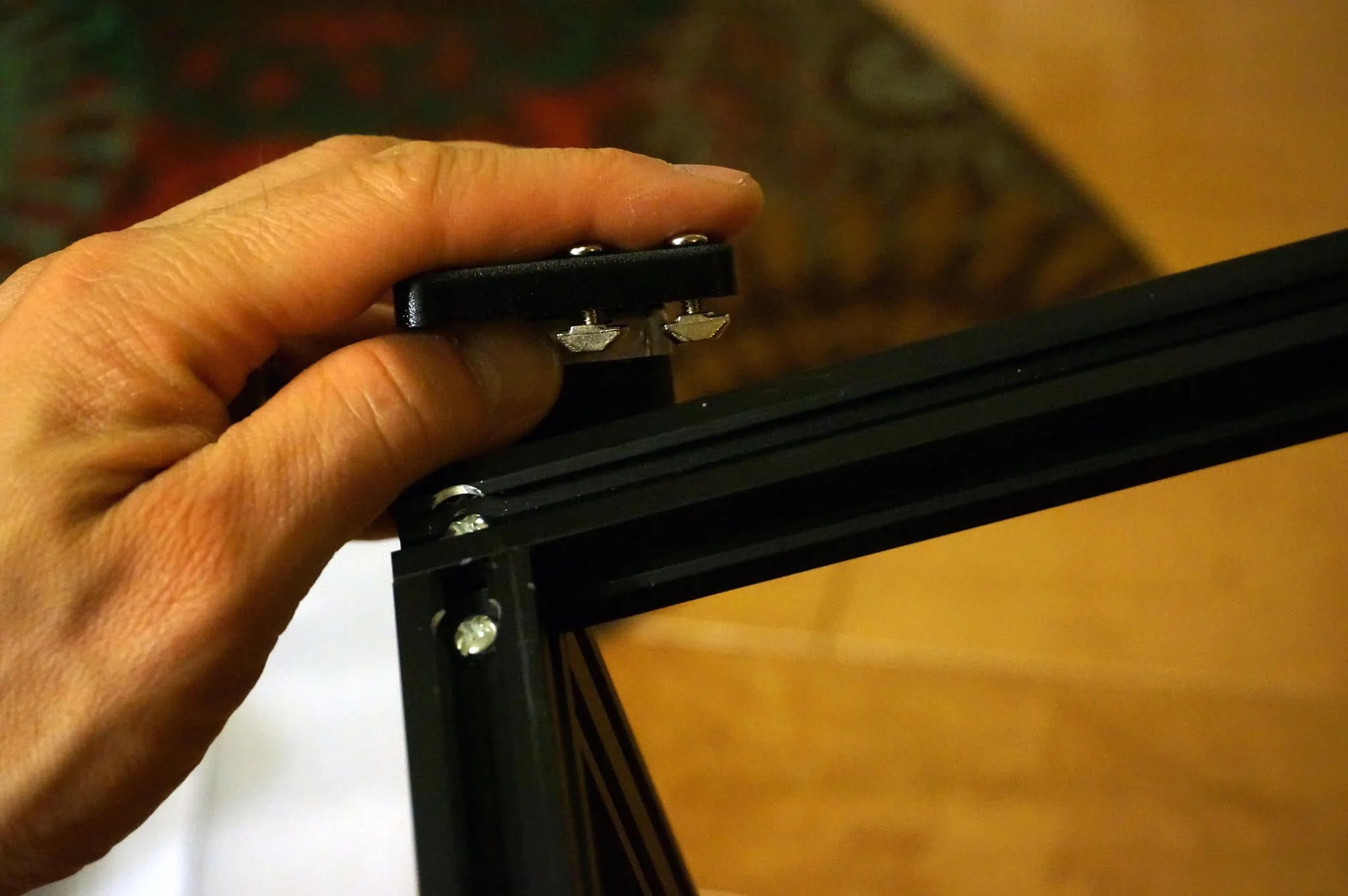
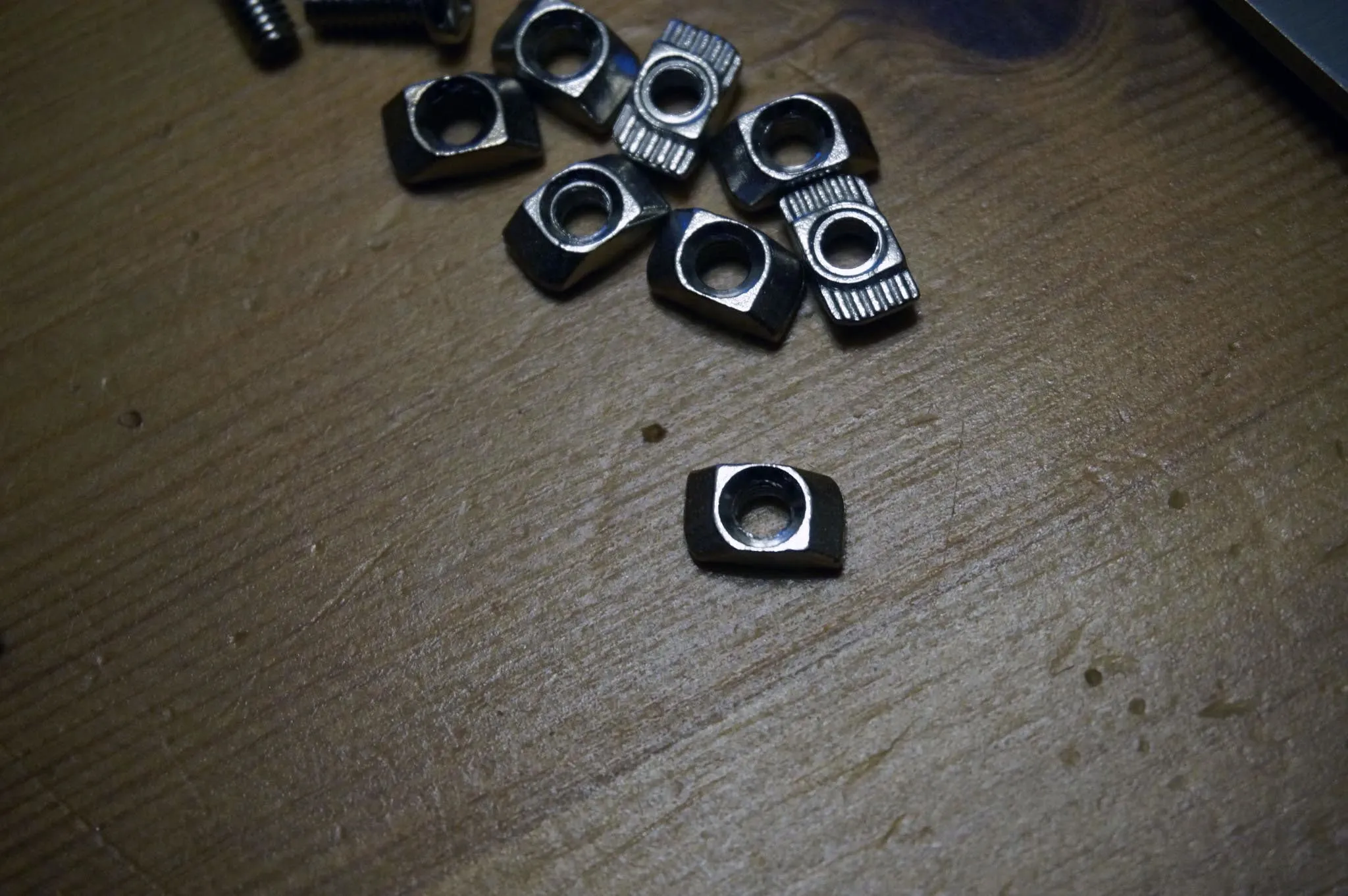
P.S. This is how the T-nuts do that cool trick where they rotate into place but not further (notice how 2 corners are rounded):
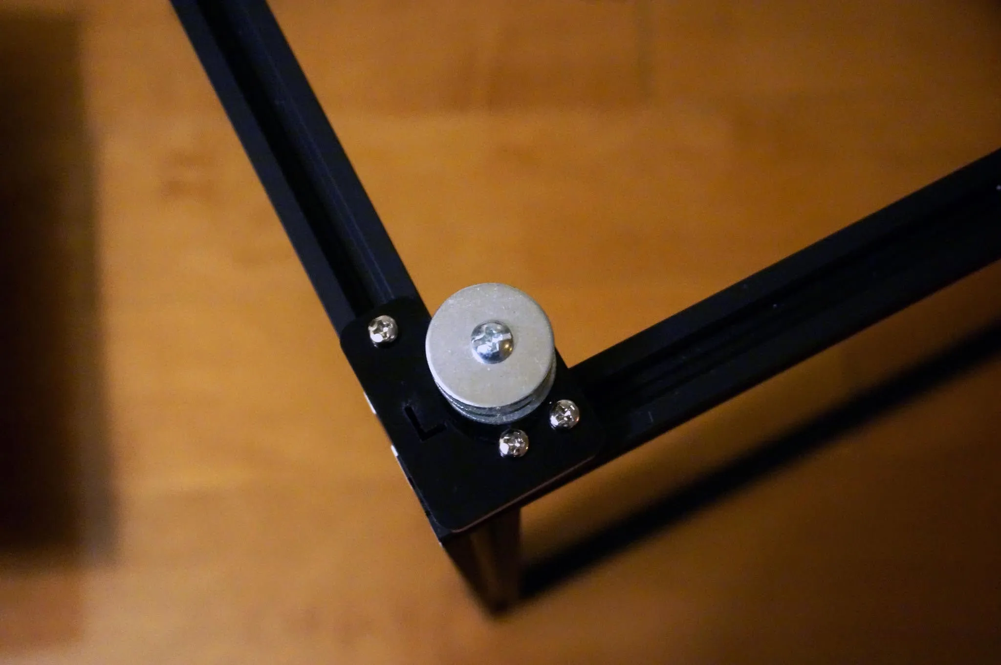
Install the pulleys on the opposing corners using 6x 3mm x 10mm bolts and 6x T-nuts.
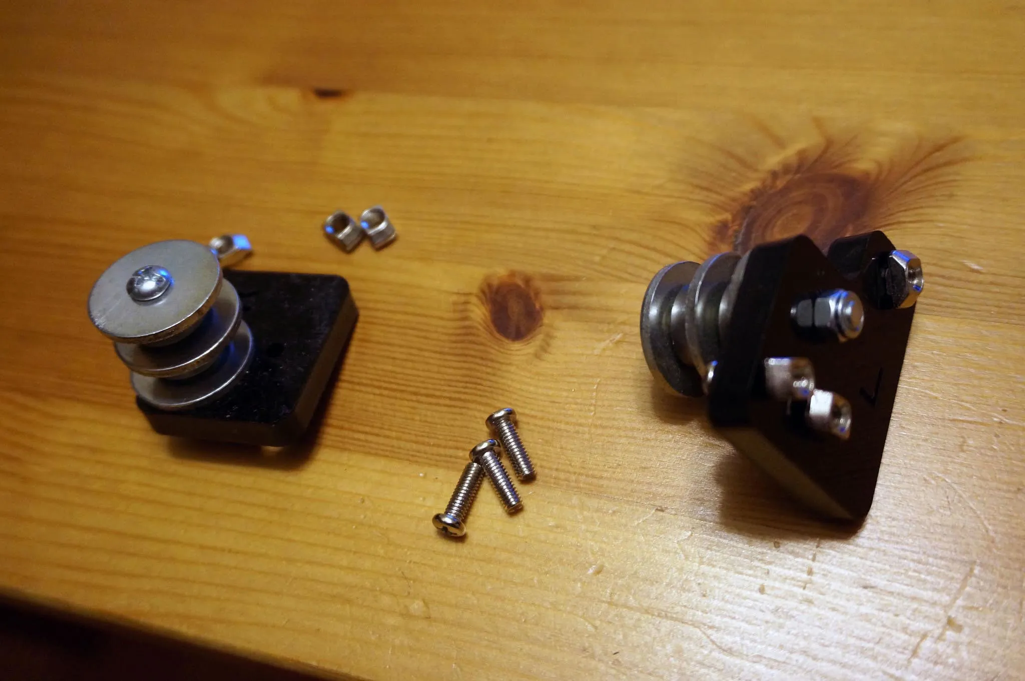
It’ll look like this when you’re done.
Z-Carriage
Next, let’s assemble the z-carriage.
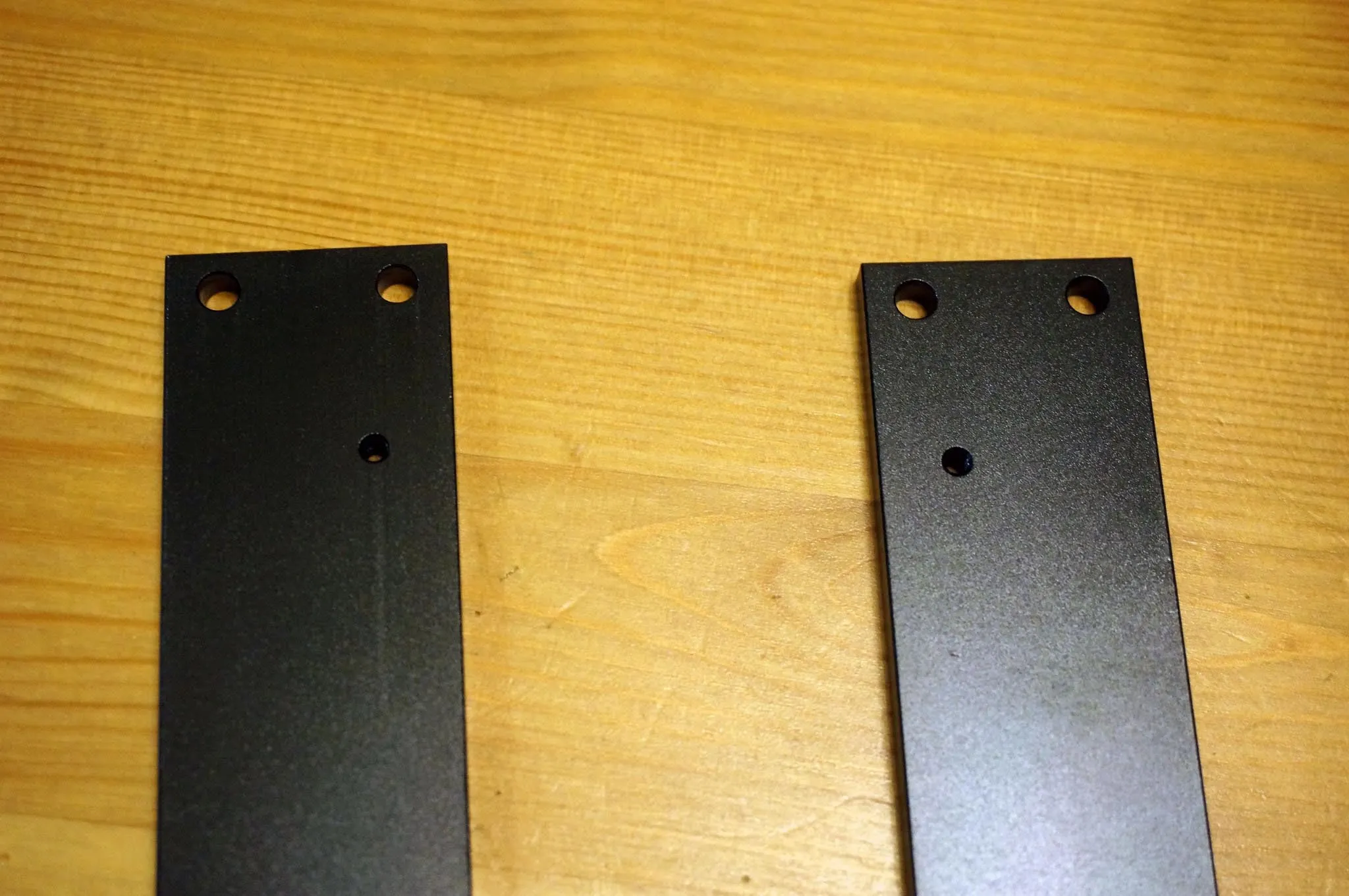
Use 12x 3mm x 8mm bolts to attach the 2 linear bearings and 1 guide nut to the two carriage ends.
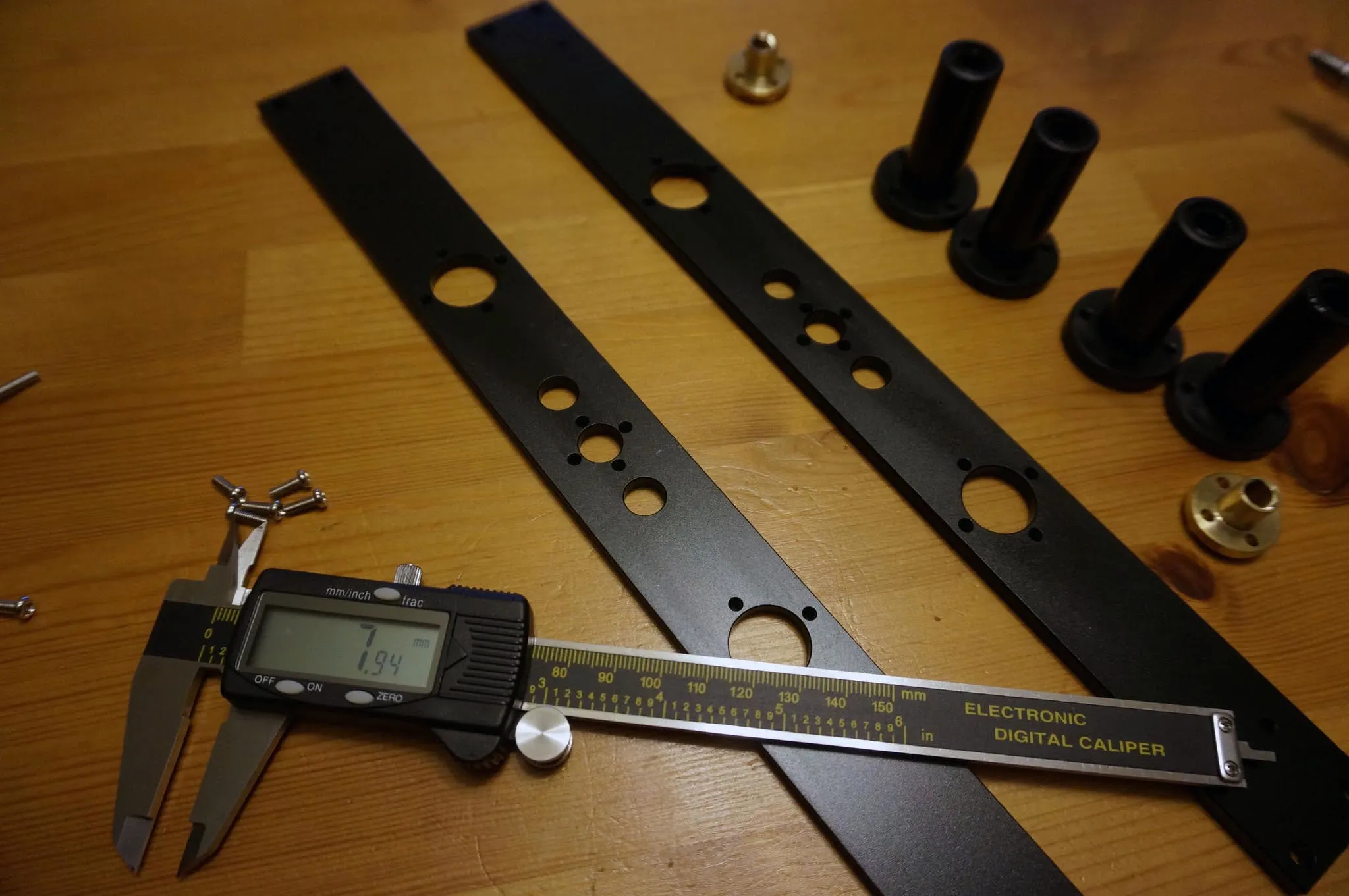
These extra holes are for the end stop screw and should be oriented towards the outside of the printer. You’ll see in some photos I’ve done this the wrong way, so I had to go back and put them on the outside.
Here they are assembled.
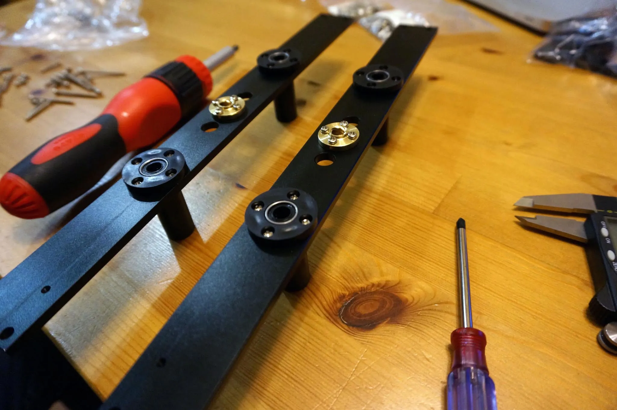
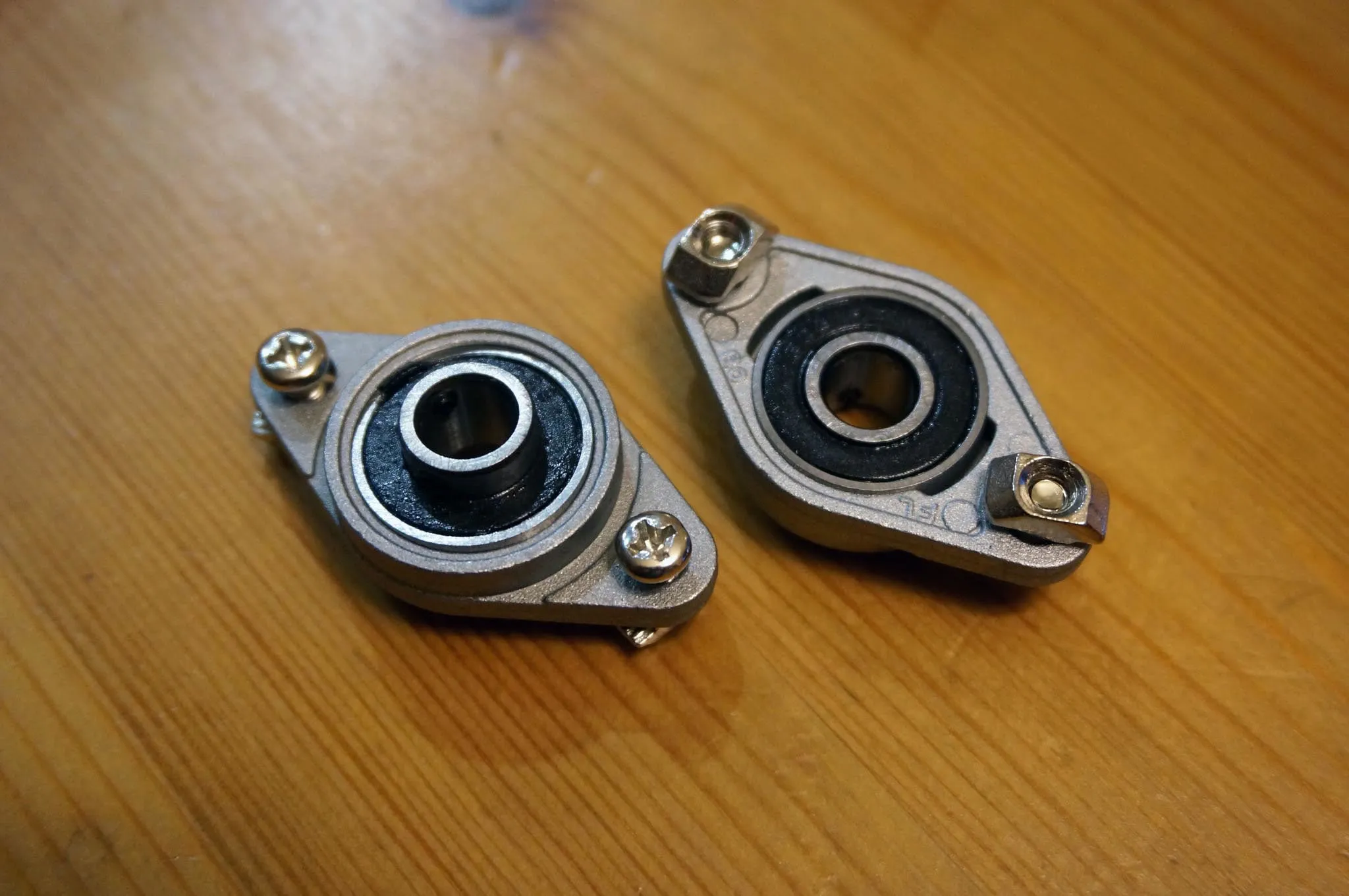
Prep the bearings with 4mm x 8mm bolts and T-nuts.
Prep the z-axis motors using 4mm x 8mm bolts and T-nuts as well.
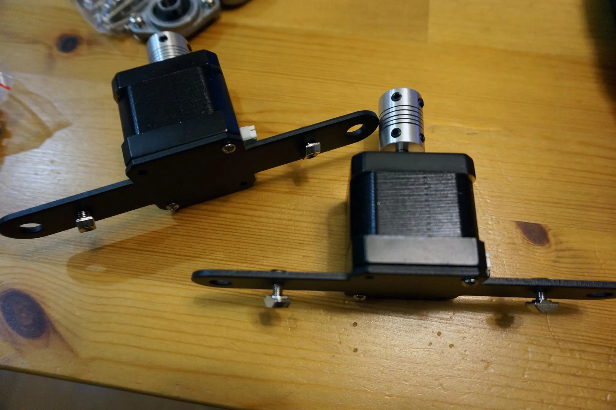
Loosely install the z-axis motors.
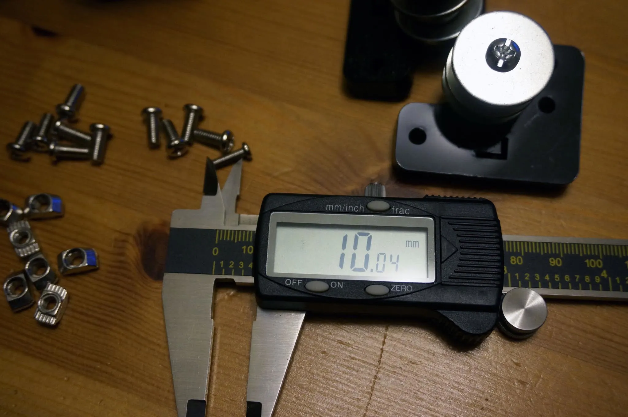
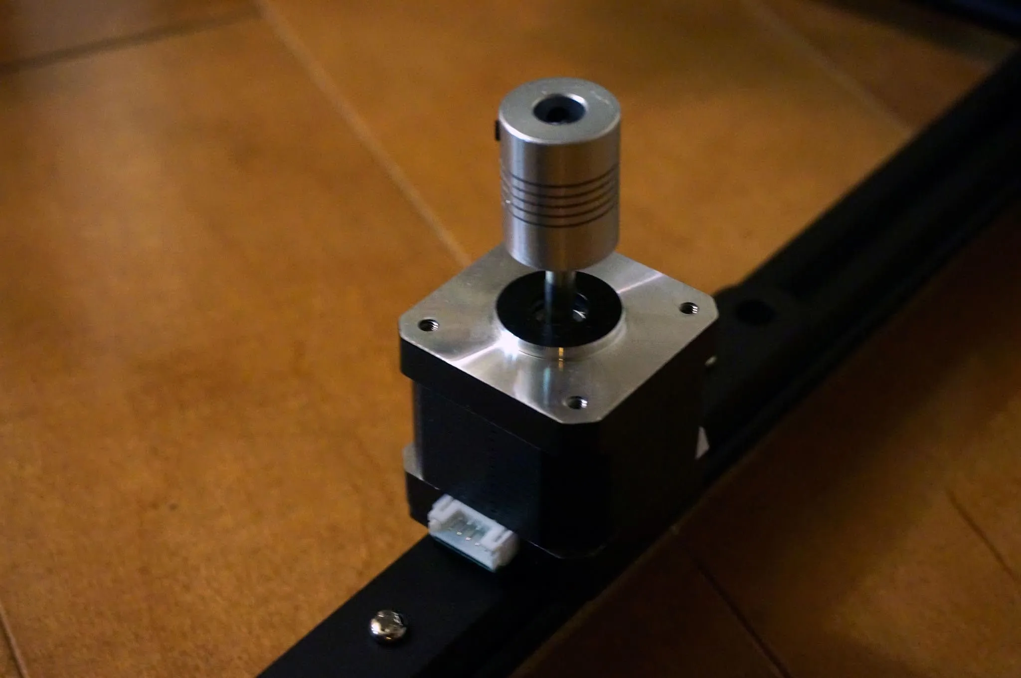
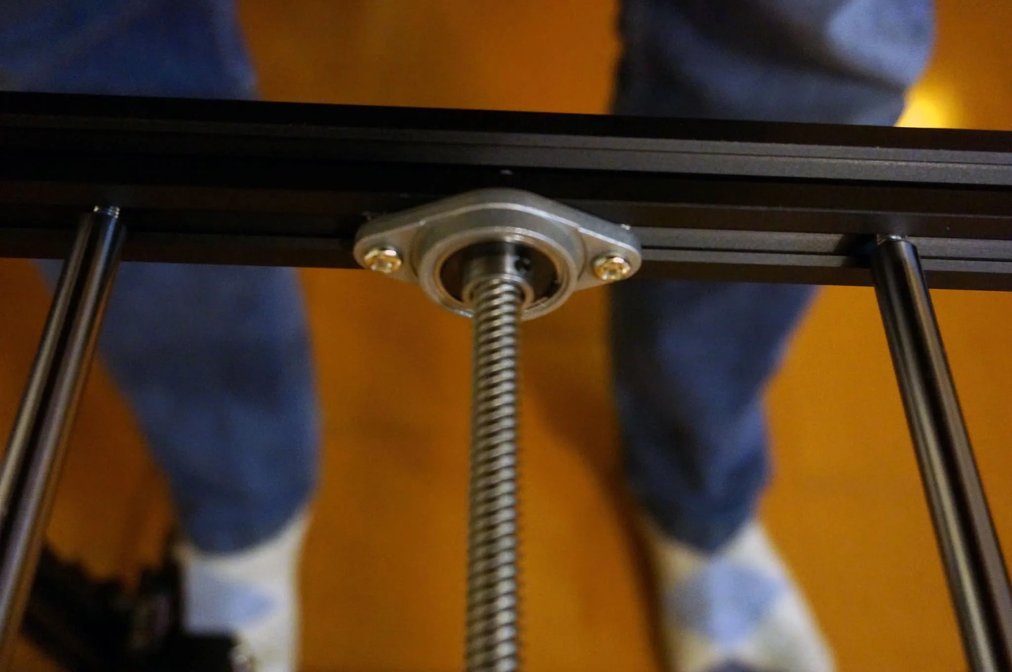
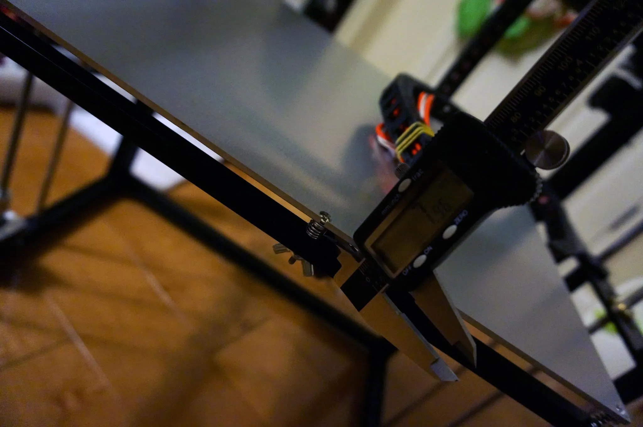
Tighten both couplers to the motors using the set screws. I like to make sure they’re as close to the same height (using calipers) as possible for easier measurement from the top of the coupler to the bed later. This helps when leveling the printer.
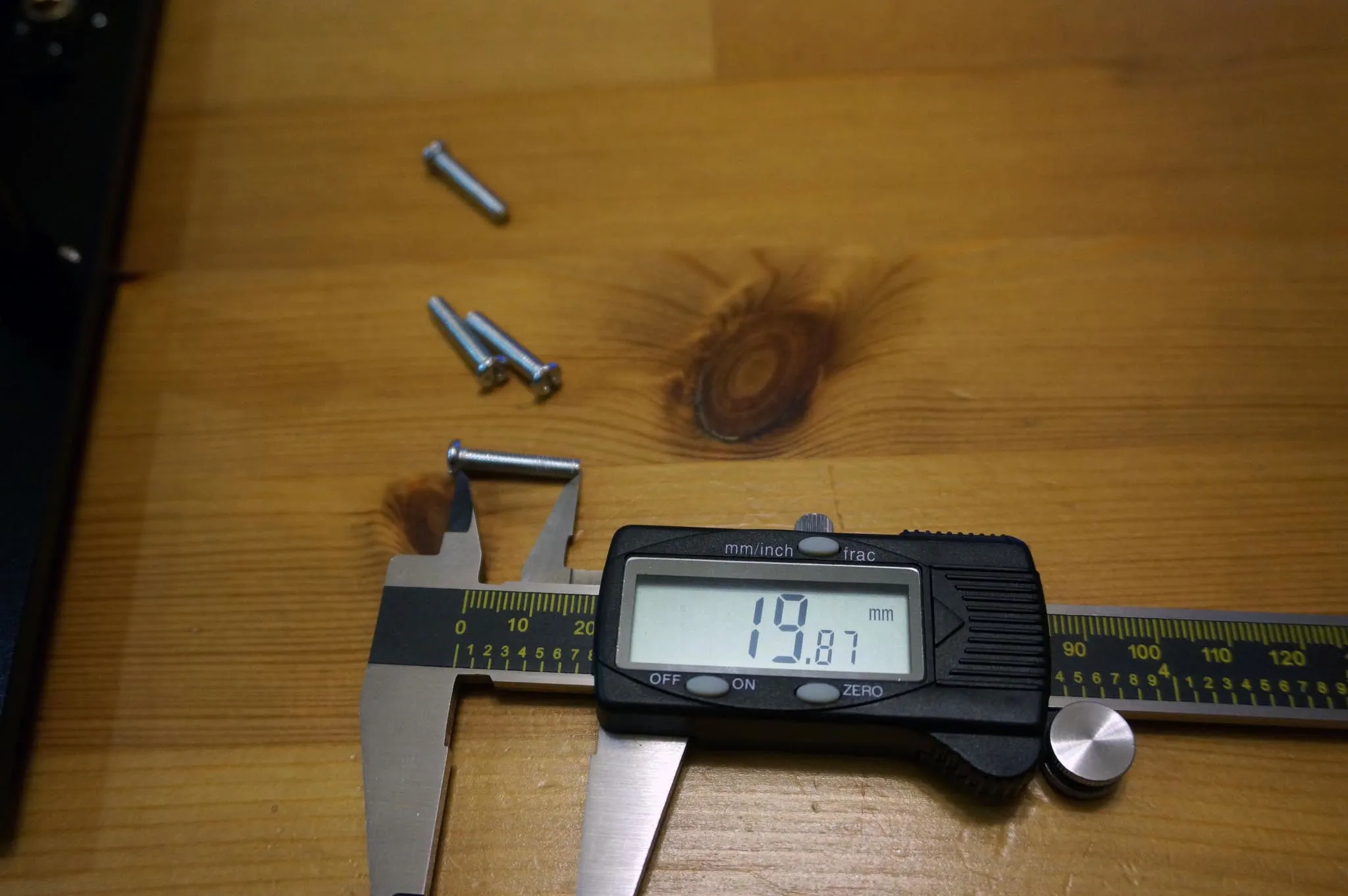
Now insert the threaded rod and two linear rods into the carriage and slip the bearing holder over the top. Install with 4x 4mm x 20mm bolts into the linear rods. I tightened the two on the bottom first, then gently snugged up the top two bolts.
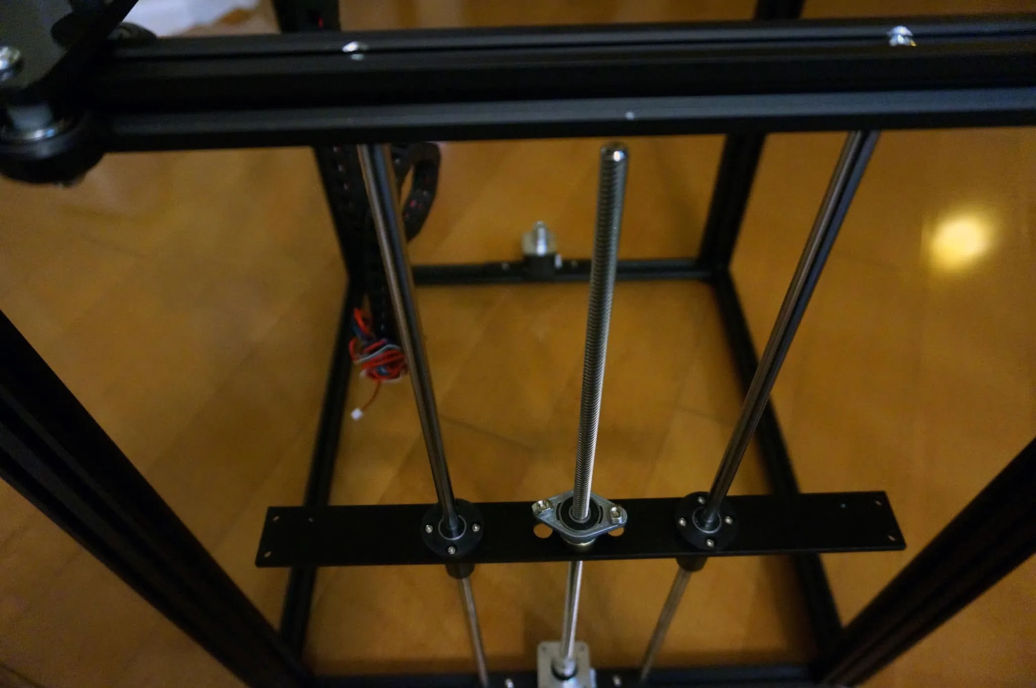
Slide the bearing holder up and snug up both the T-nut bolts and the set screws on the bearing holder and the motor coupler.
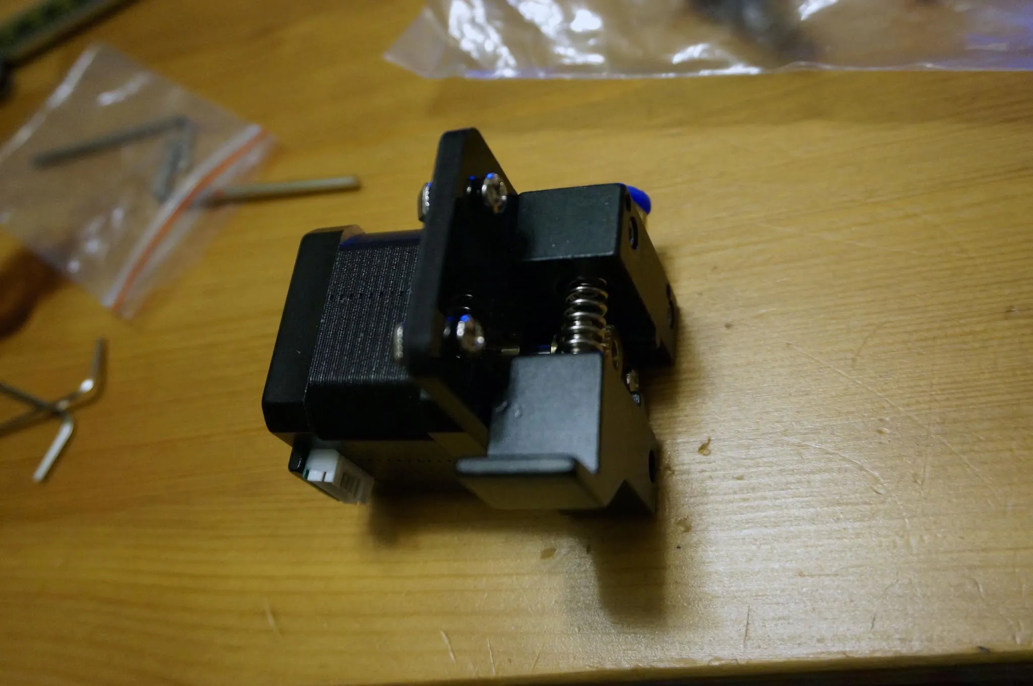
Install the extruder motor with two 4mm x 8mm bolts and T-nuts.
Bed assembly
Here is the hardware you’ll need:
8x 4mm x 12mm bolts to attach the assembly to the z-axis carriages on either side
6x 3mm x 30mm bolts
6x 3mm nuts
6x springs
6x wingnuts
6x lock washers (or thread lock)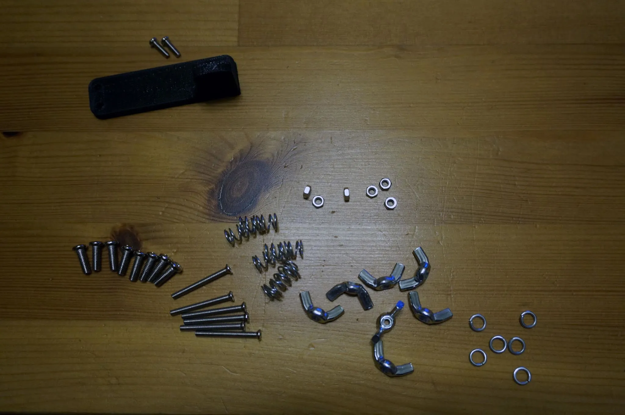
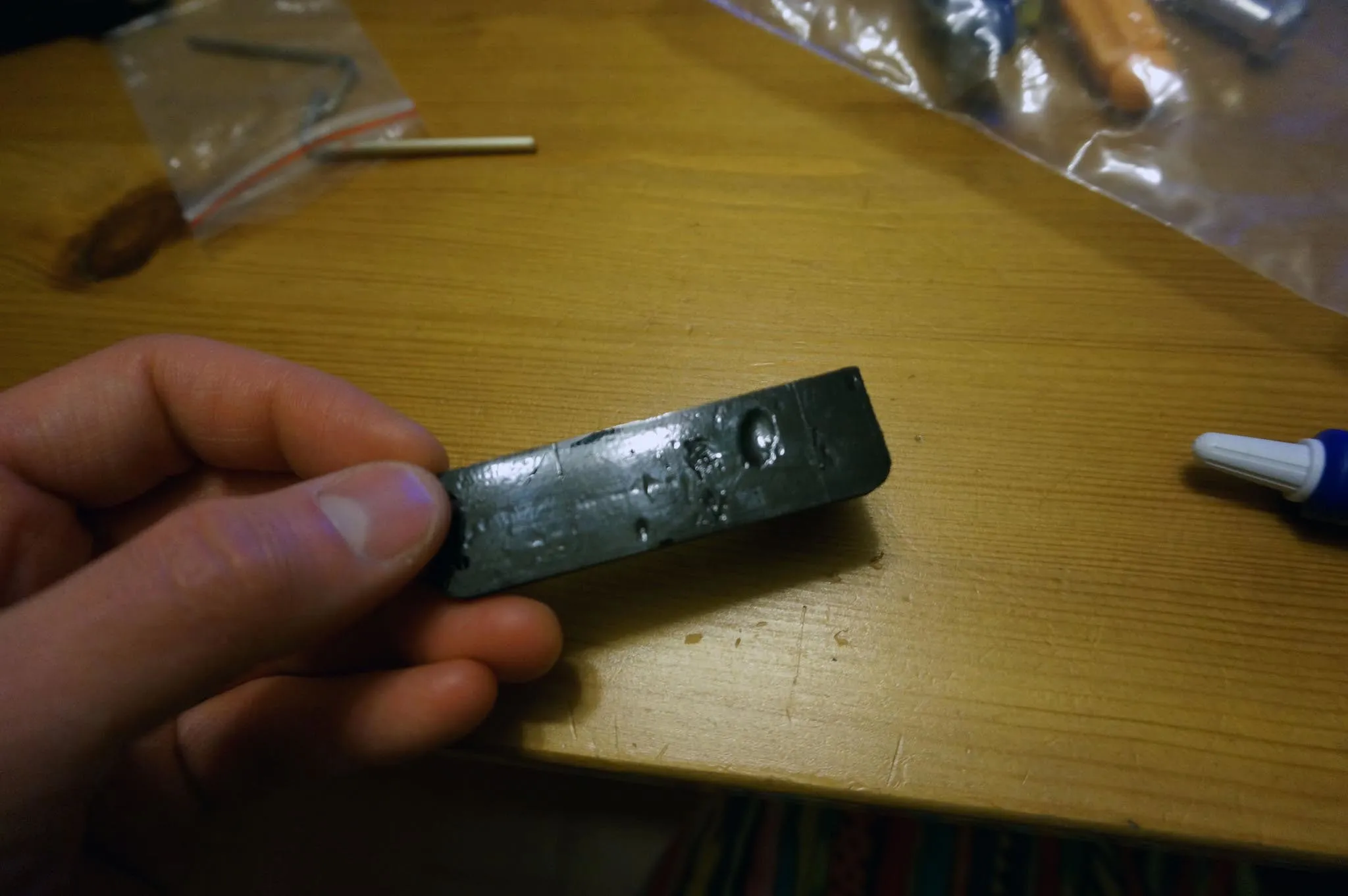
And for later, the only 3D printed part in the kit, for the cable chain adapter. This attaches with 2x 3mm x 10mm bolts.
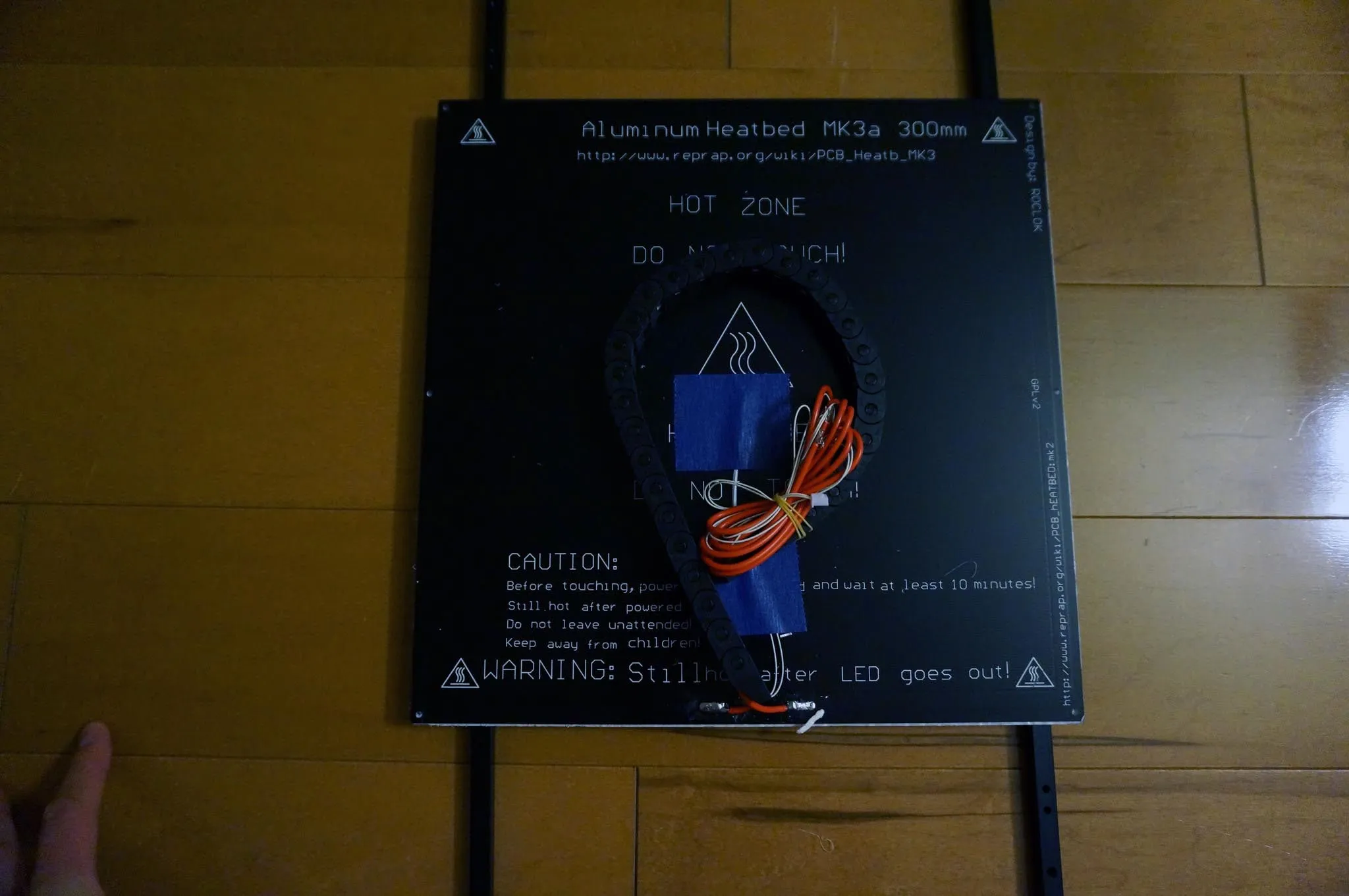
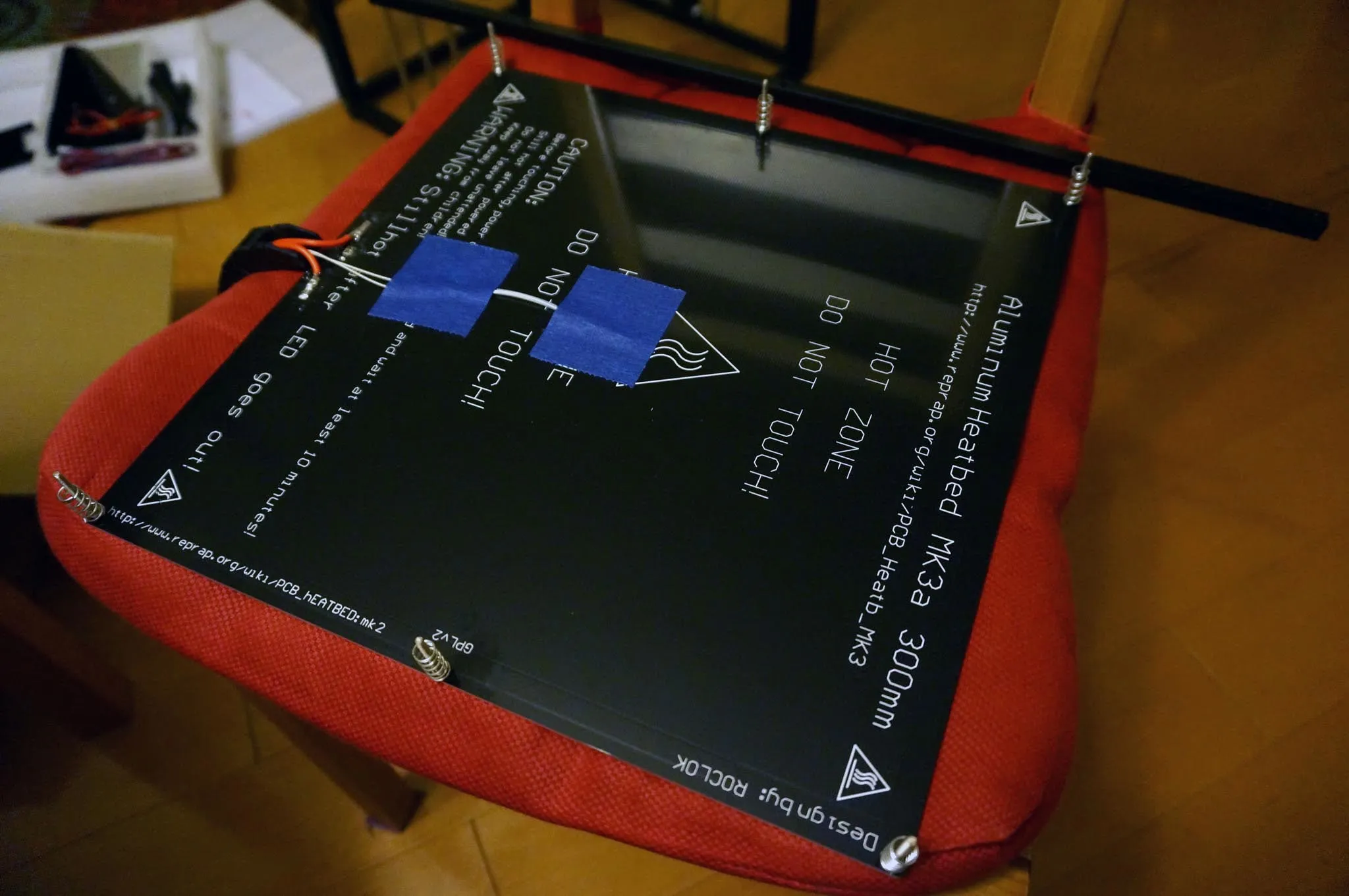
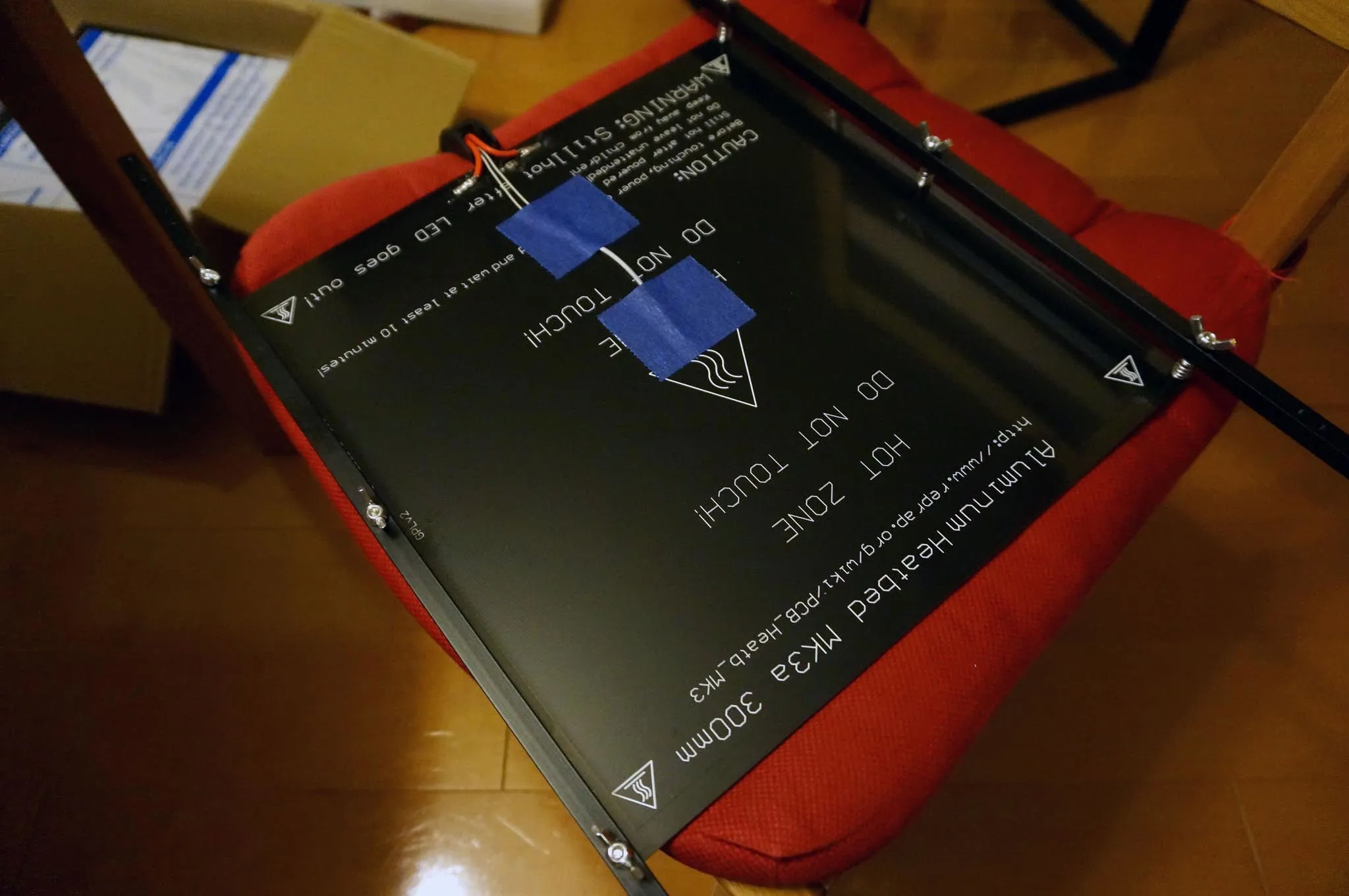
Find the heated bed and remove the protective film.
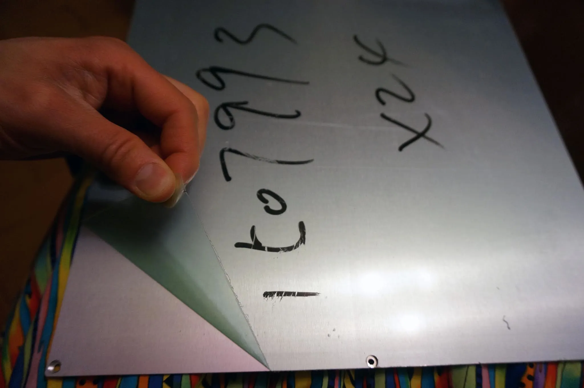
Using thread lock or the lock washers, attach each 30mm bolt to the heated bed. I highly suggest using a screwdriver and pliers to make sure these nuts are very tight. It will make it much easier to work with later if these bolts cannot move.
Install the springs, then the bars and wing nuts.
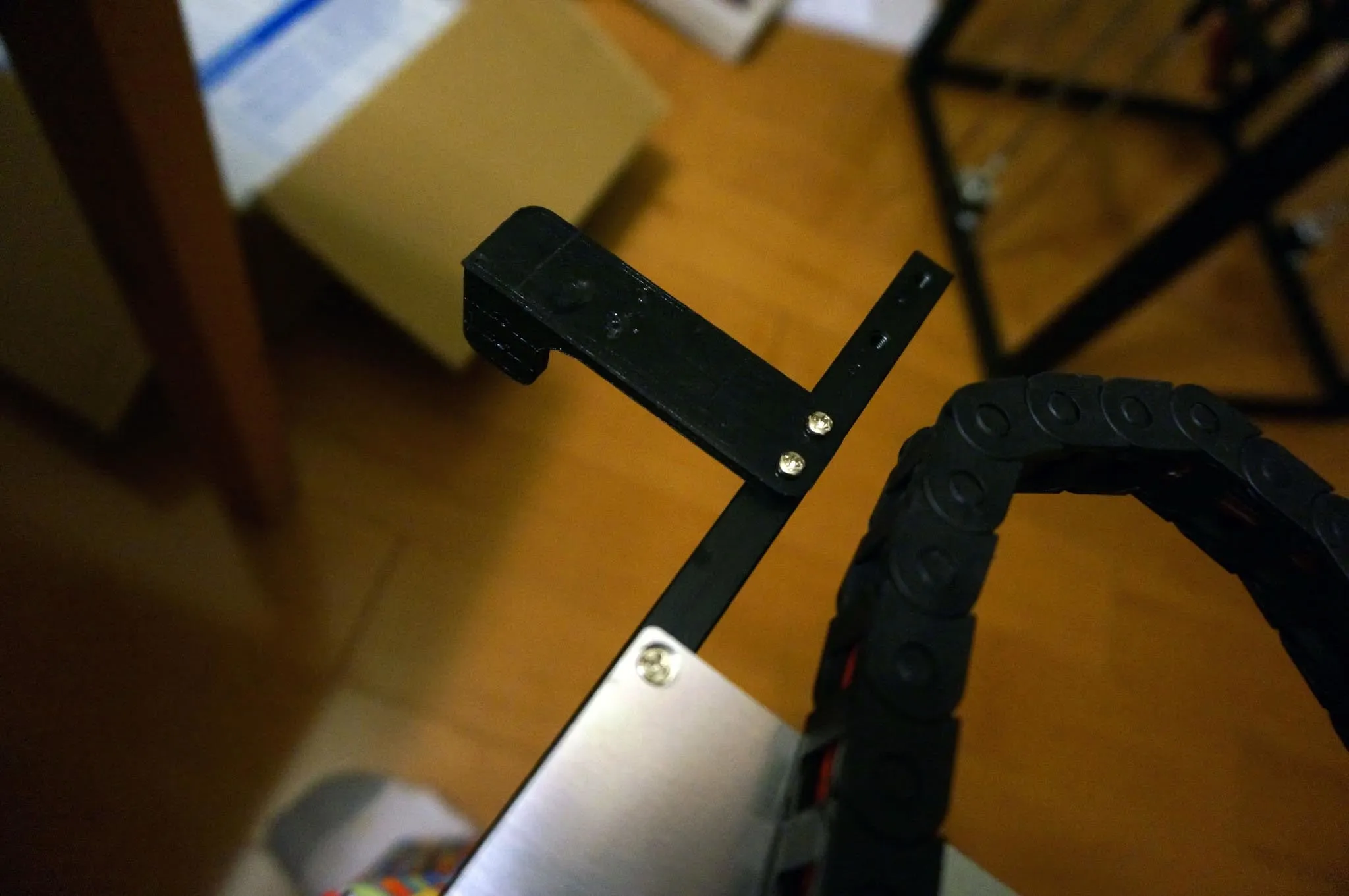
Install the cable chain guide.
And finally, install the bed.
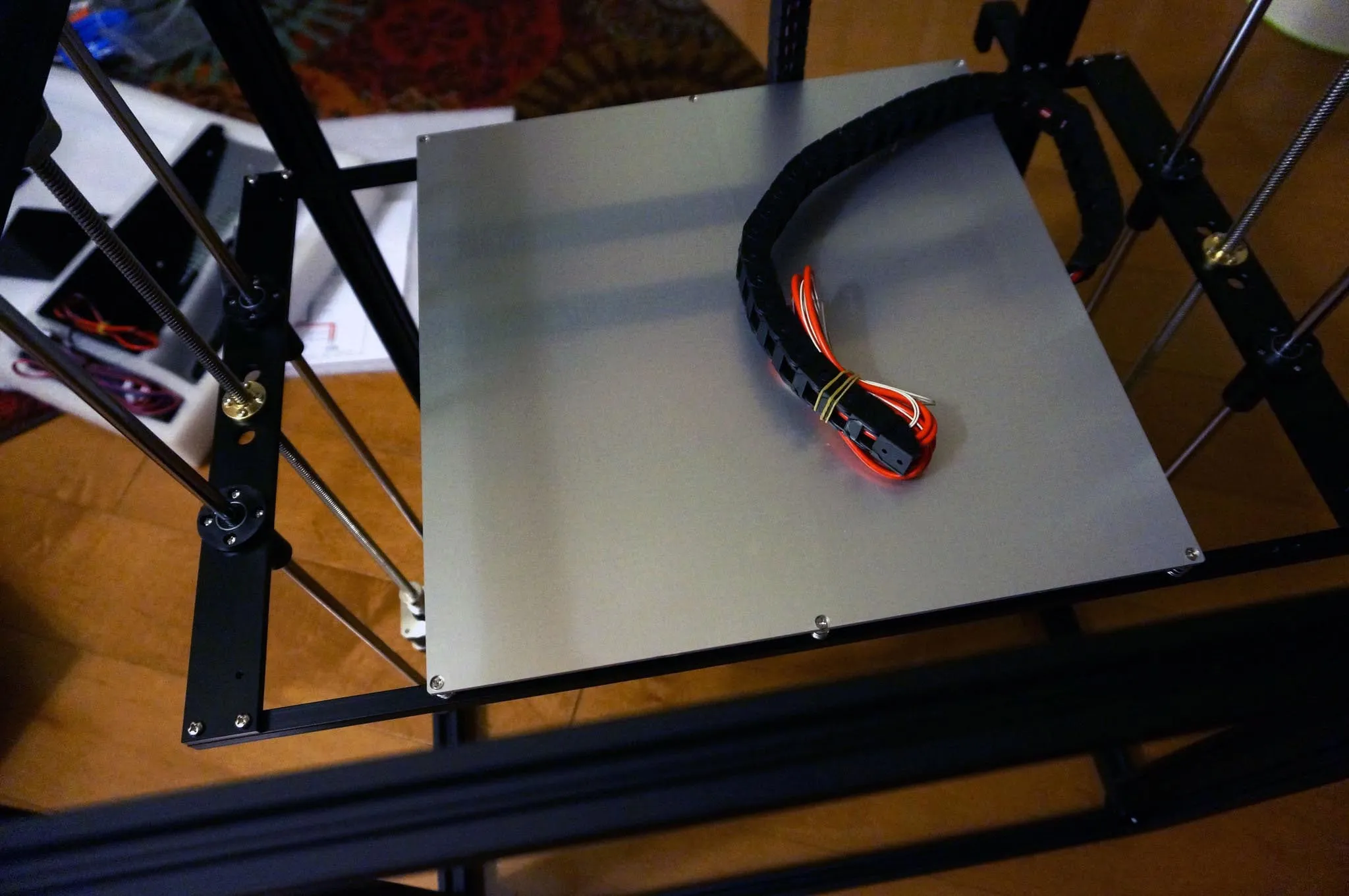
Tighten the wing nuts down so there is 8mm between the bed and the frame. 8mm is what the manual suggests, but this seems somewhat arbitrary. Adjust as you see fit.
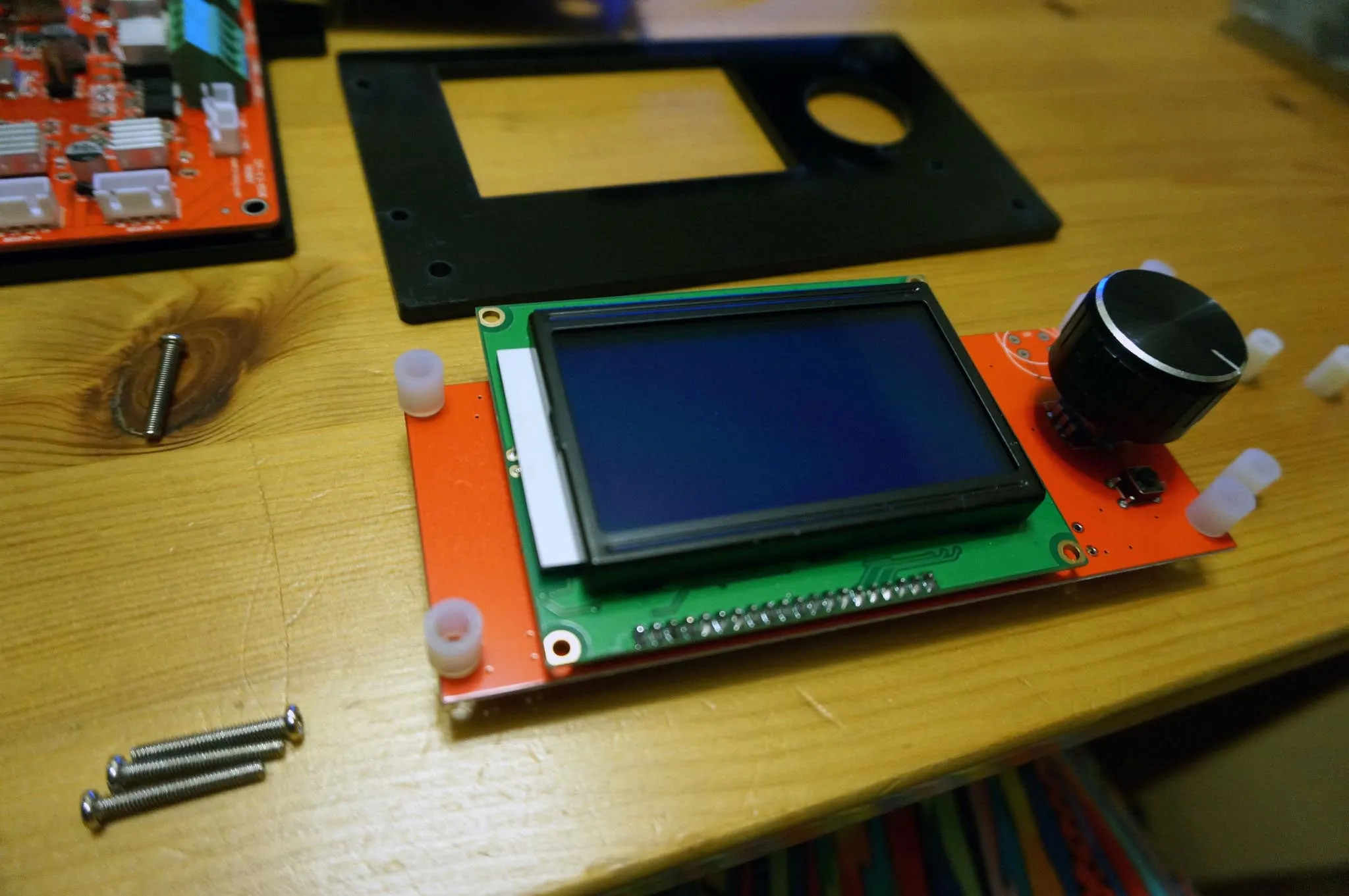
Next, I used 4x 3mm x 20mm bolts and the 8.5mm standoffs to install the LED screen. Make sure the knob spins freely in the hole in the acrylic. Mine is too tight—they should have cut it a few mm bigger—but it’s fine, I’ll take it apart and sand the hole bigger. Inserting the bolts and spacers all at once is super tricky; using a pair of tweezers to insert the spacers one at a time might be easier.
Using 3x 4mm x 8mm bolts and 3 T-nuts, install the LED panel into the frame. It would be nice if this were angled.
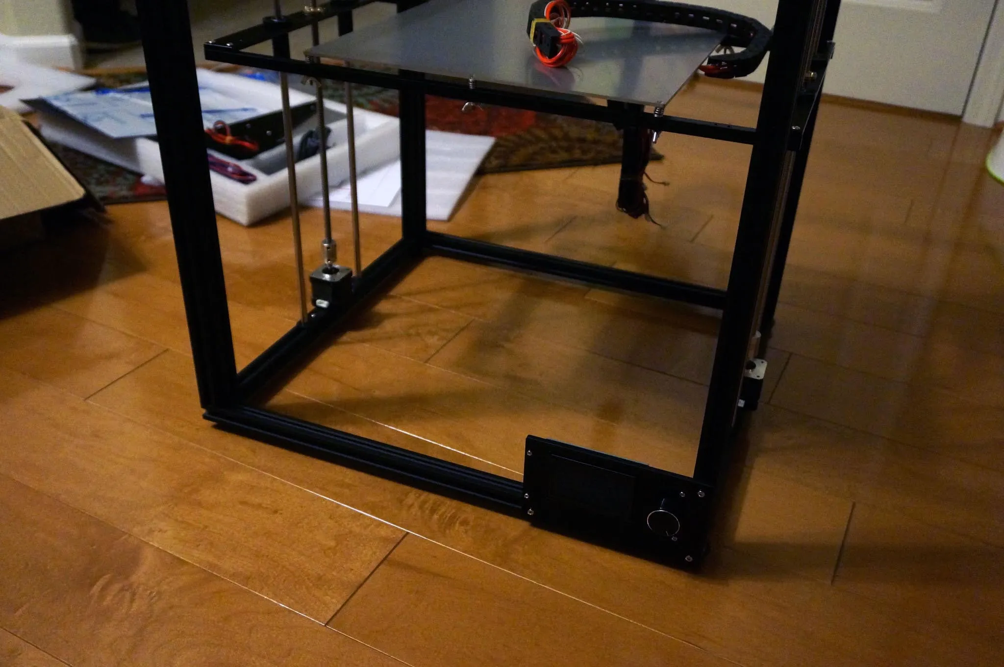
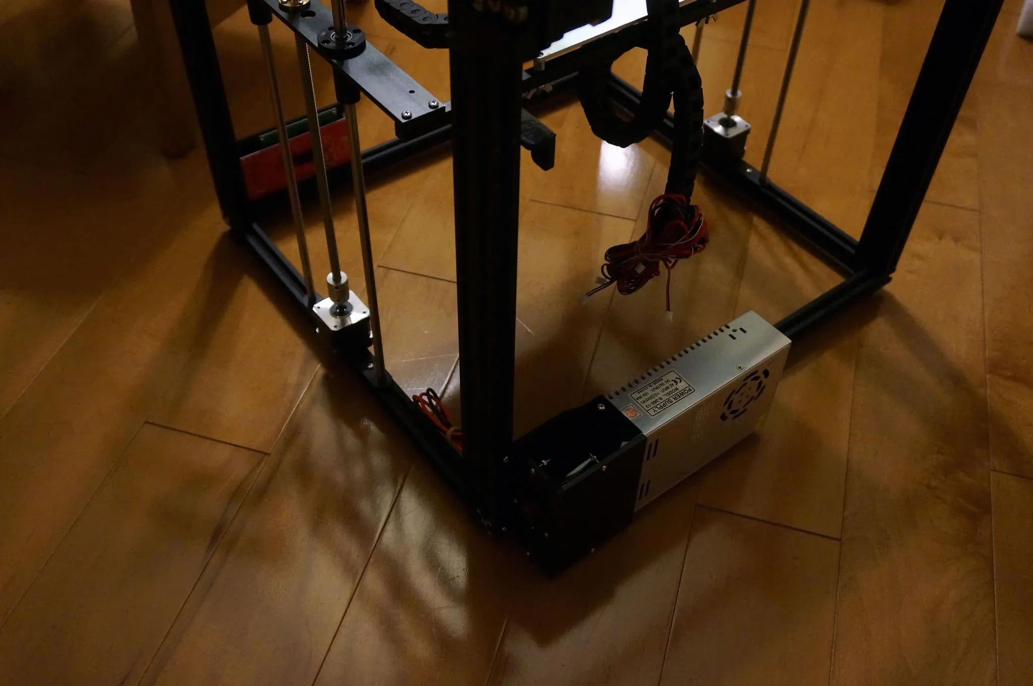
My power supply came with the acrylic case installed, so I just installed it with 3x 4mm x 8mm bolts and T-nuts. Be sure to check that the voltage switch is correct for your mains power.
Find the spool holder and install with two 4mm x 10mm bolts and T-nuts. Use two pliers or wrenches to tighten this down so your spool doesn’t come loose mid-print.
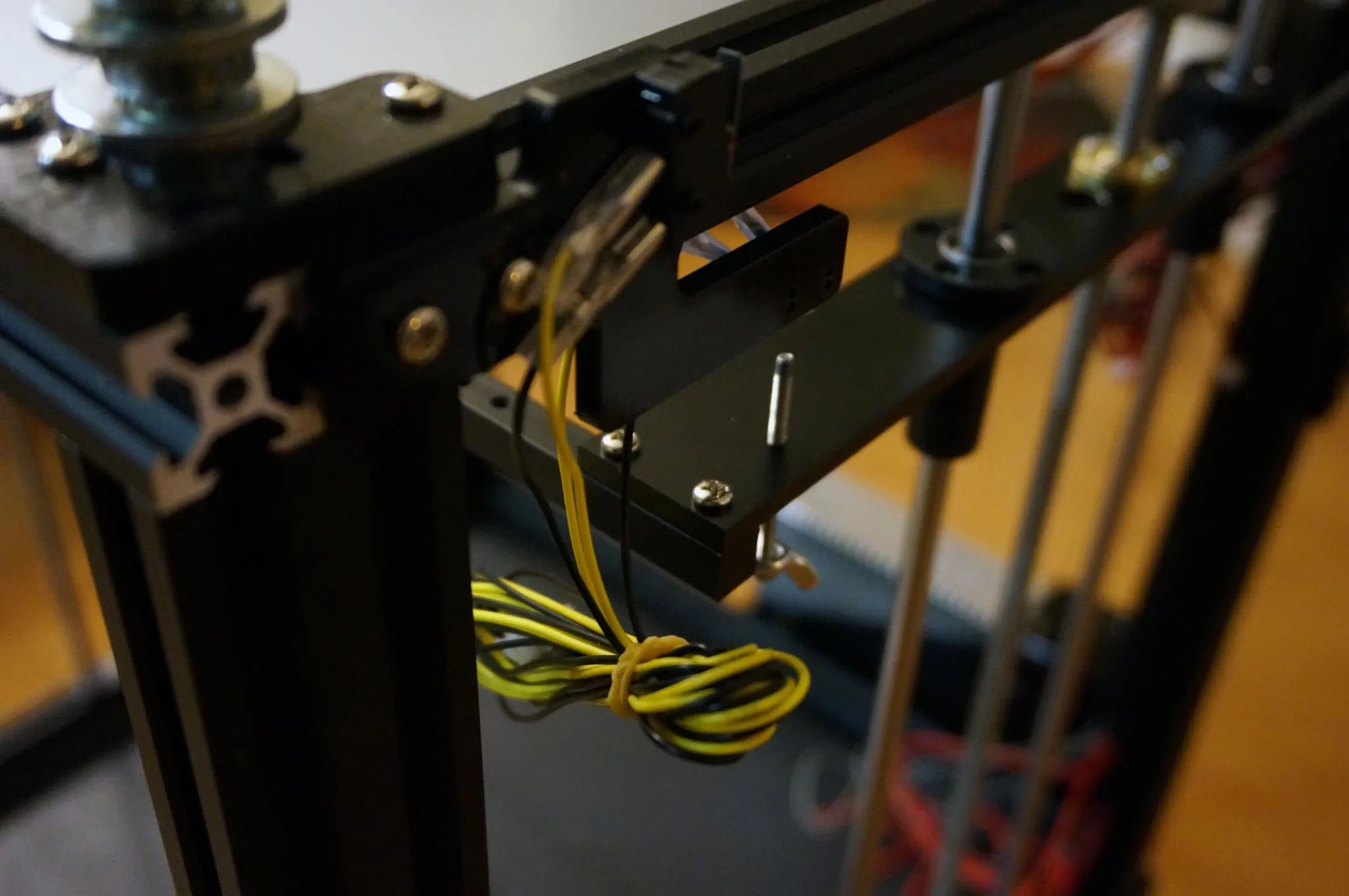
Using 4x 3mm x 10mm bolts and 4x 3mm nuts, install the z-axis cable chain.
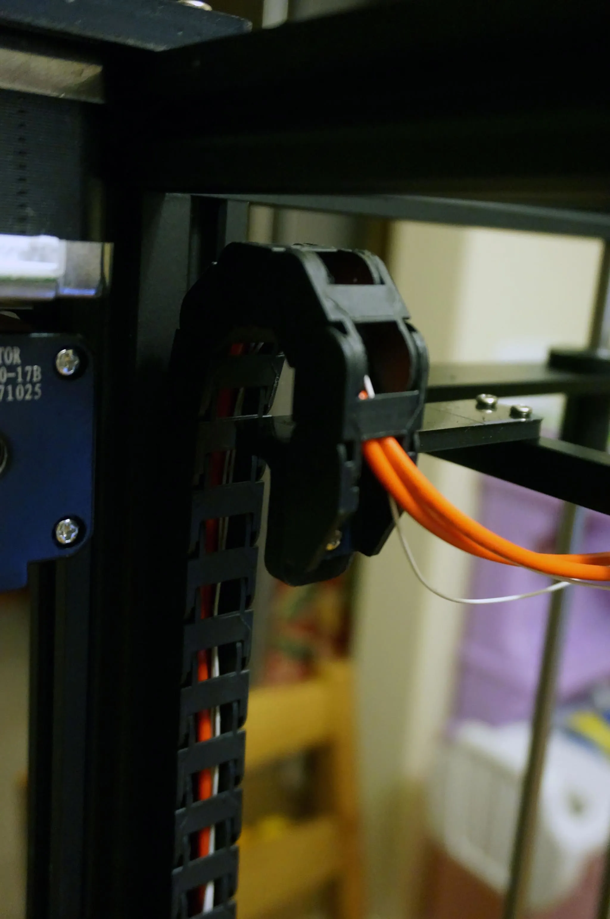
Same for the y-axis carriage.
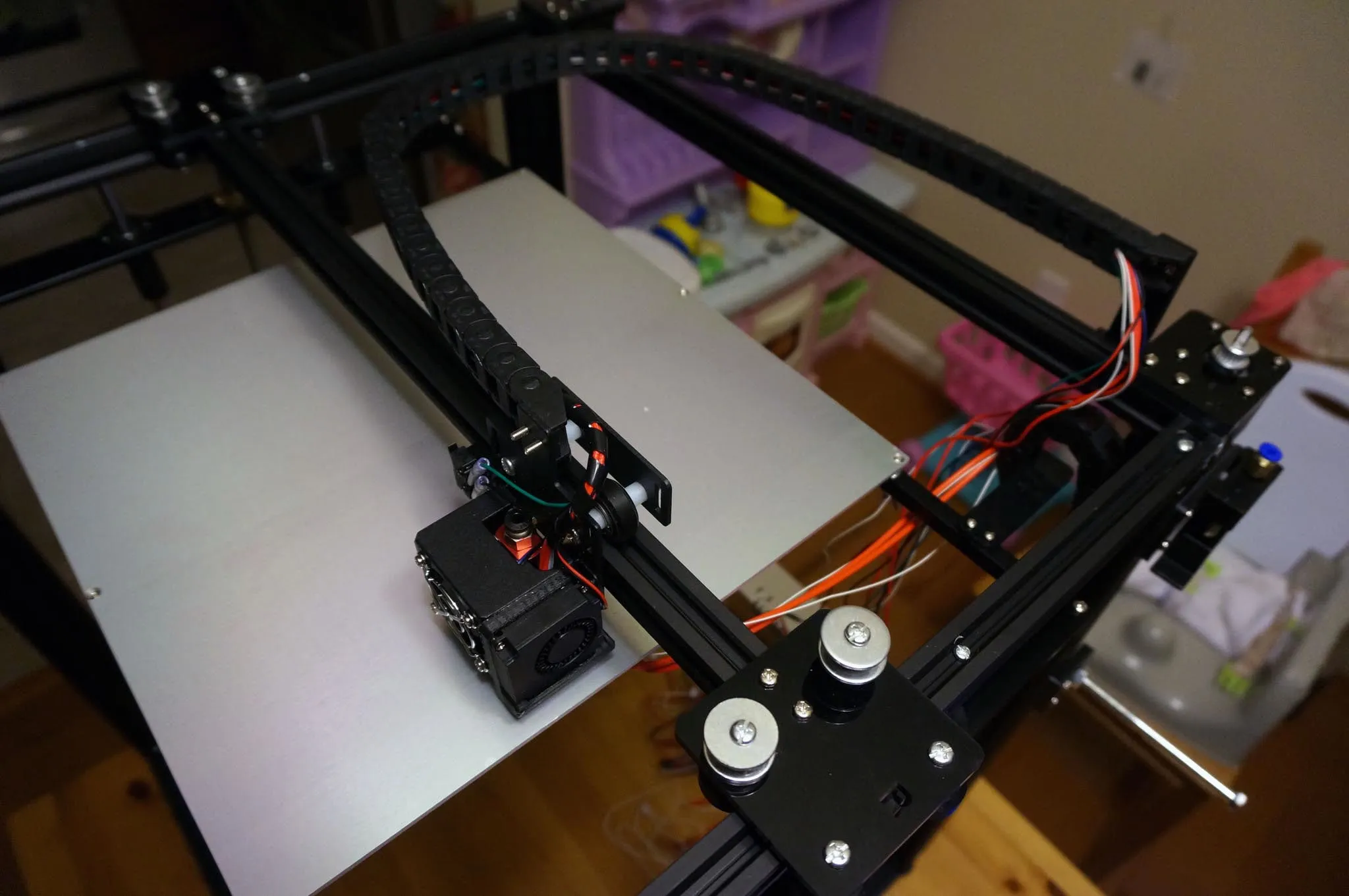
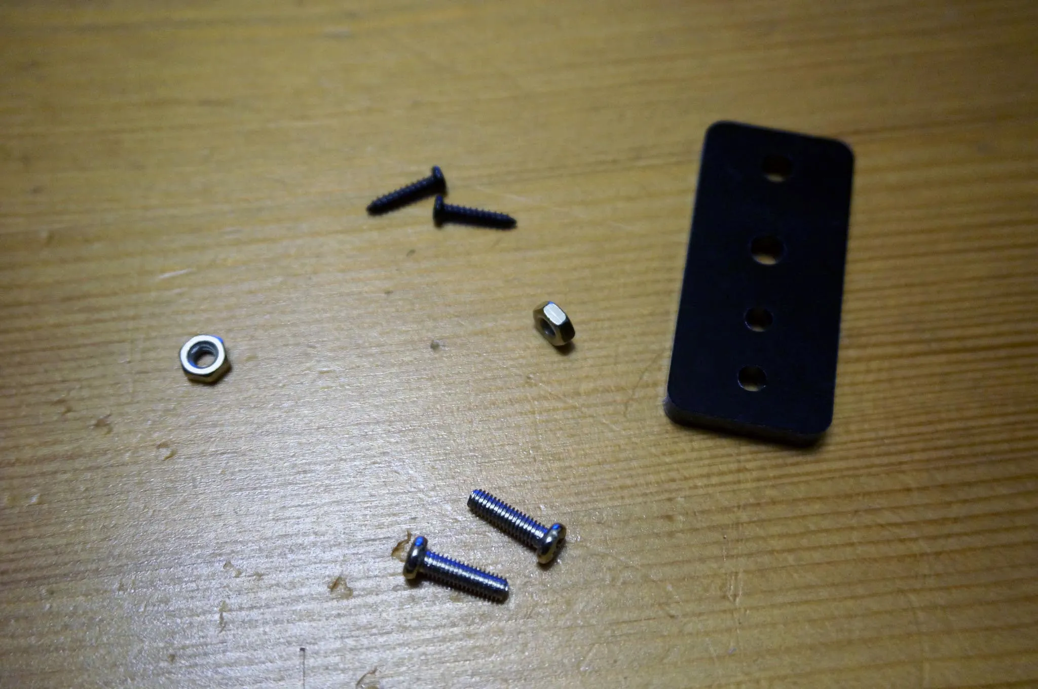
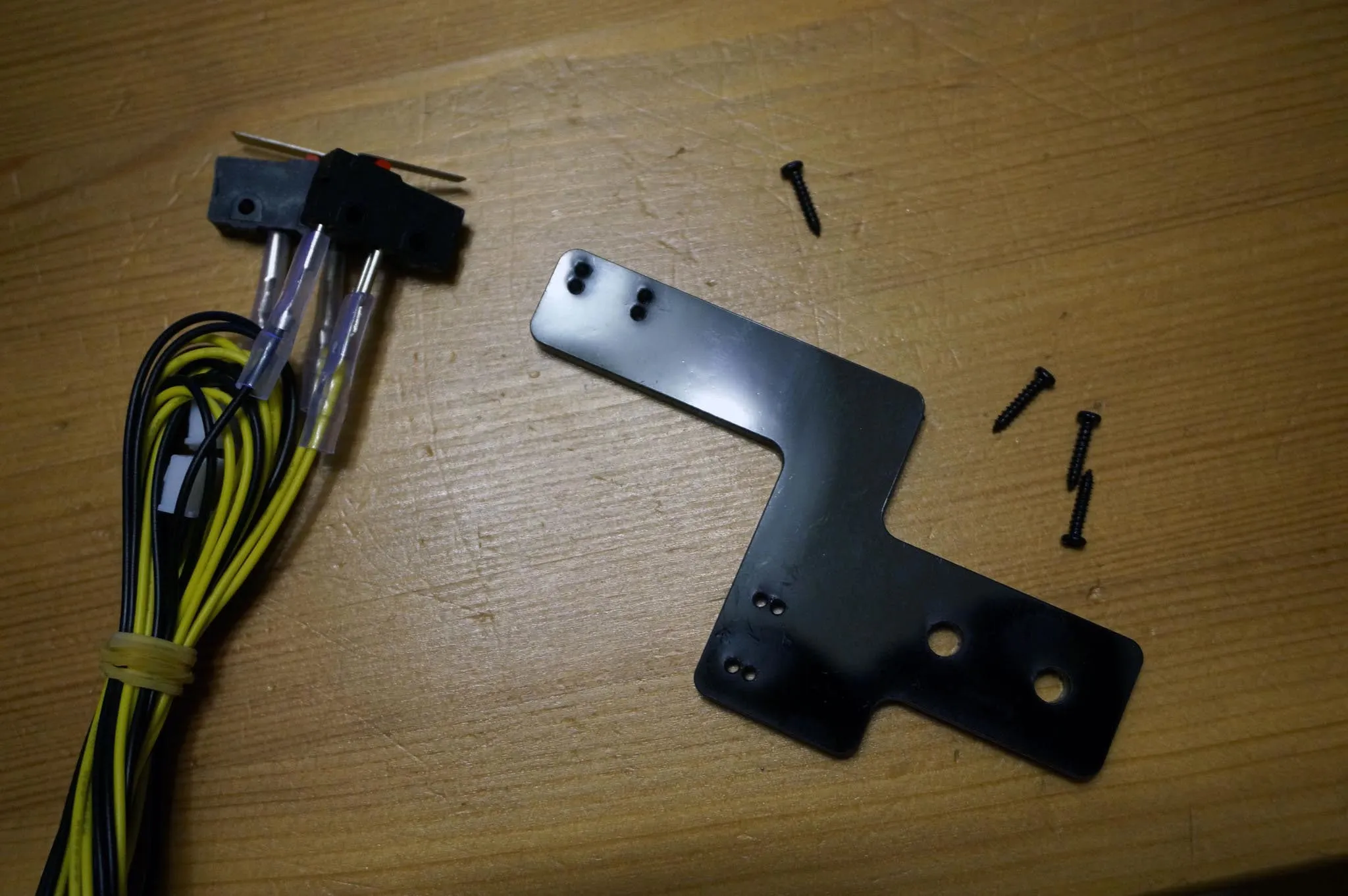
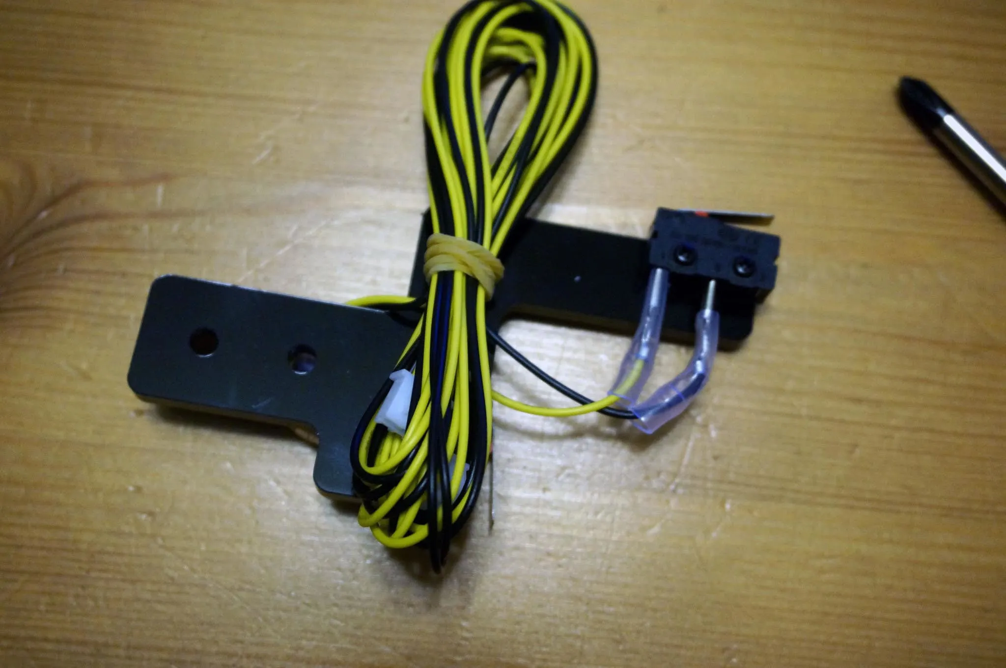
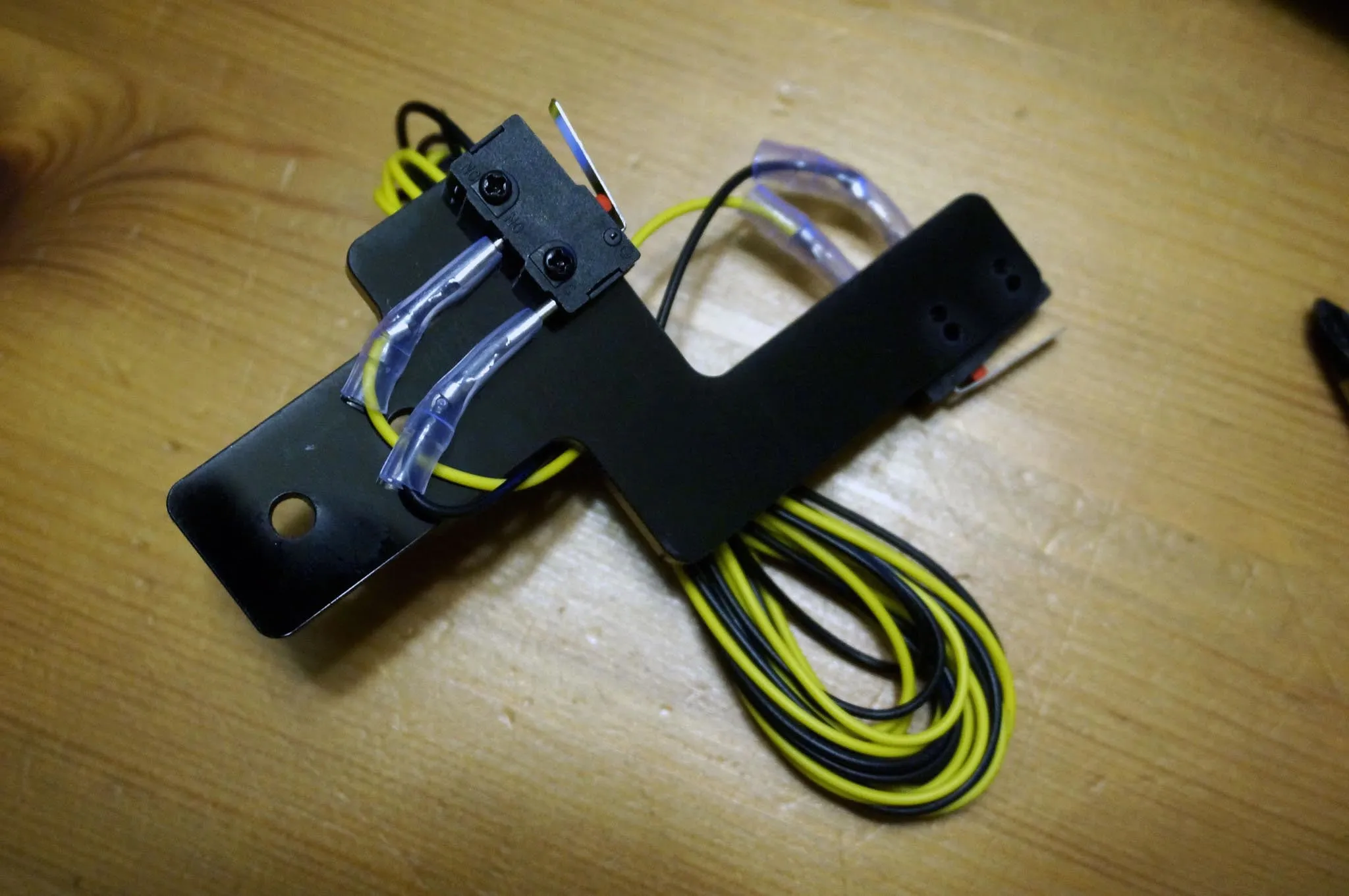
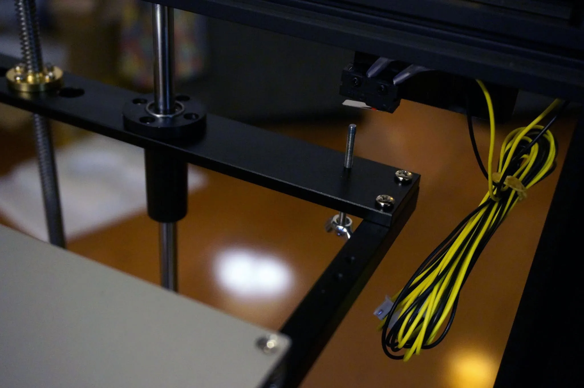
Install the end stops onto the end stop bracket like so.
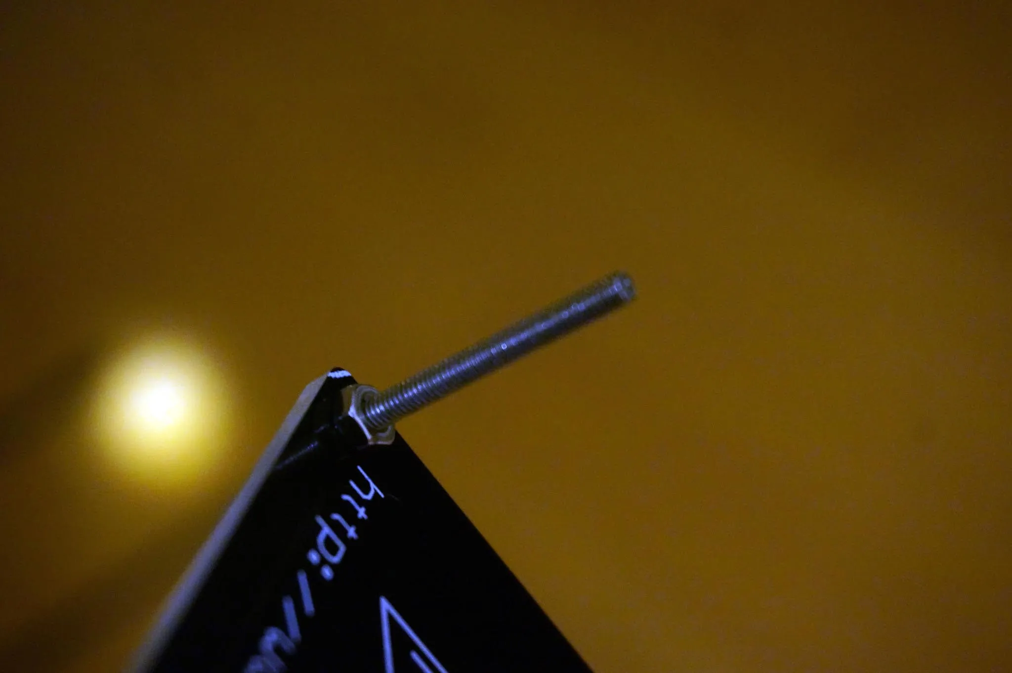
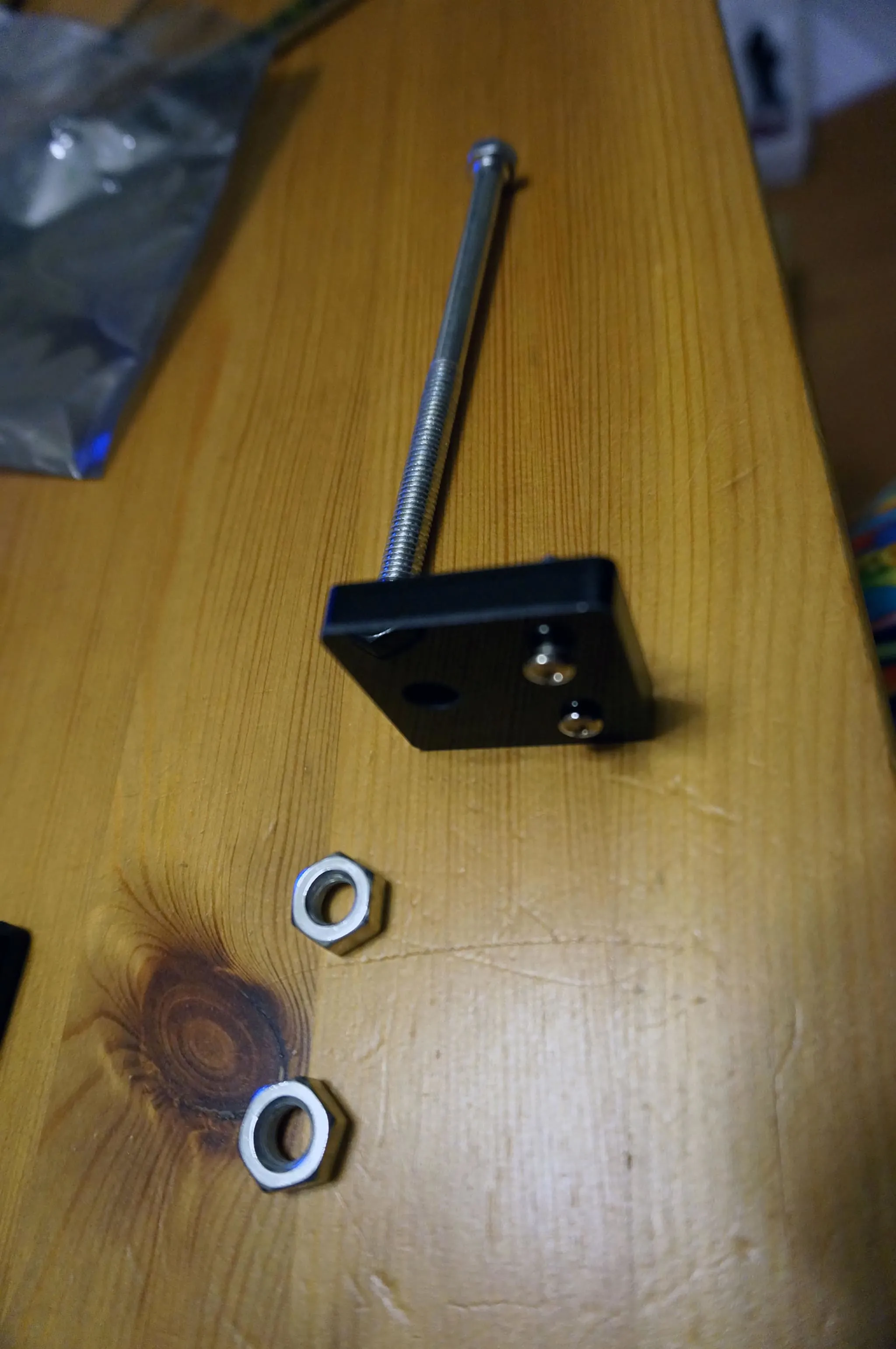
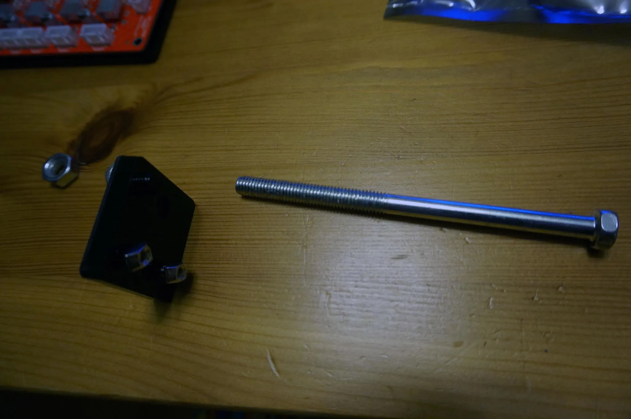
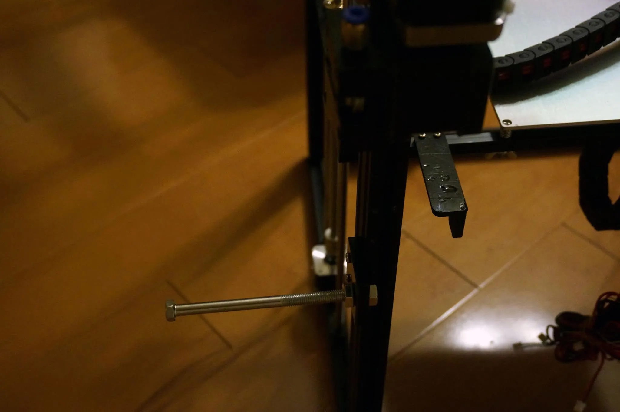
Install the last wingnut on the longest M3 screw and then insert it into the threaded hole on the z-carriage. Mount the end stop bracket.
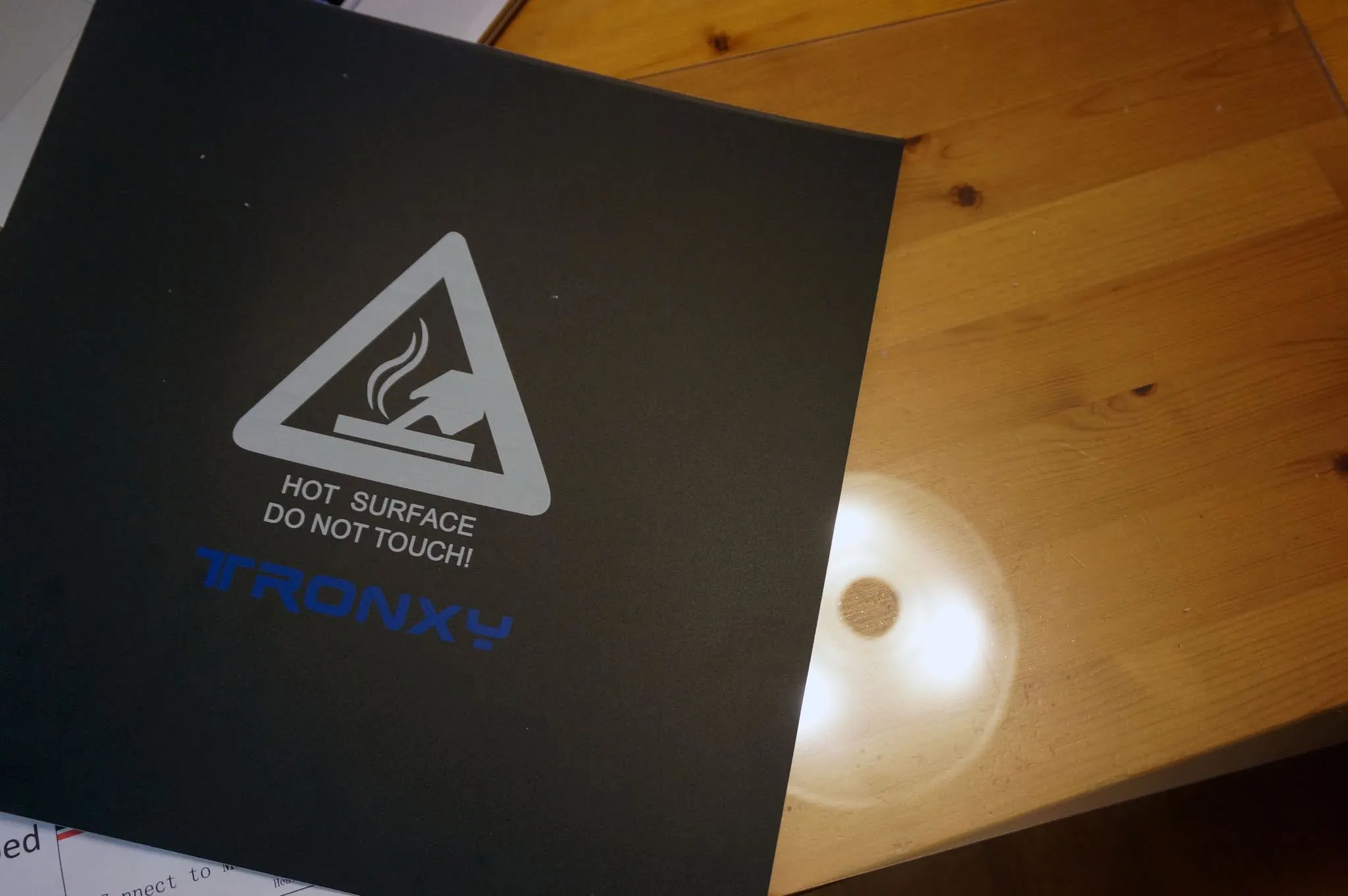
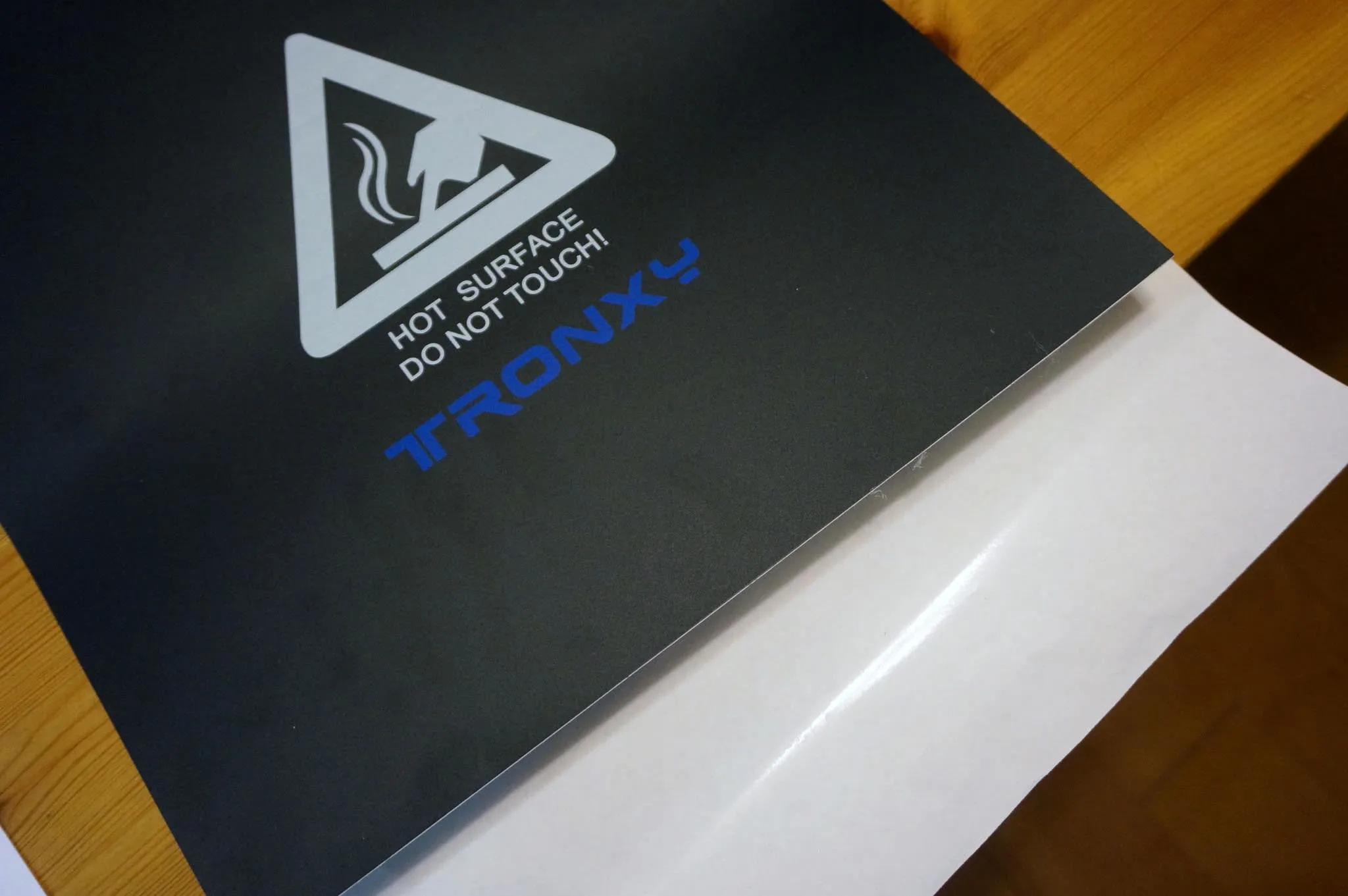
You should also have an acrylic sheet and some sort of print-bed surface in the box. I attached the plastic surface, which has an adhesive back, to the acrylic.
Belts
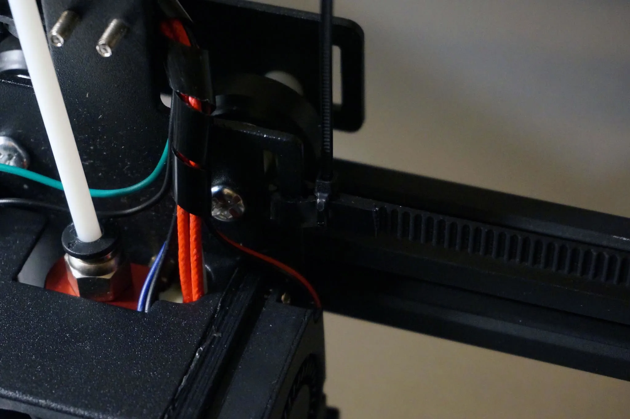
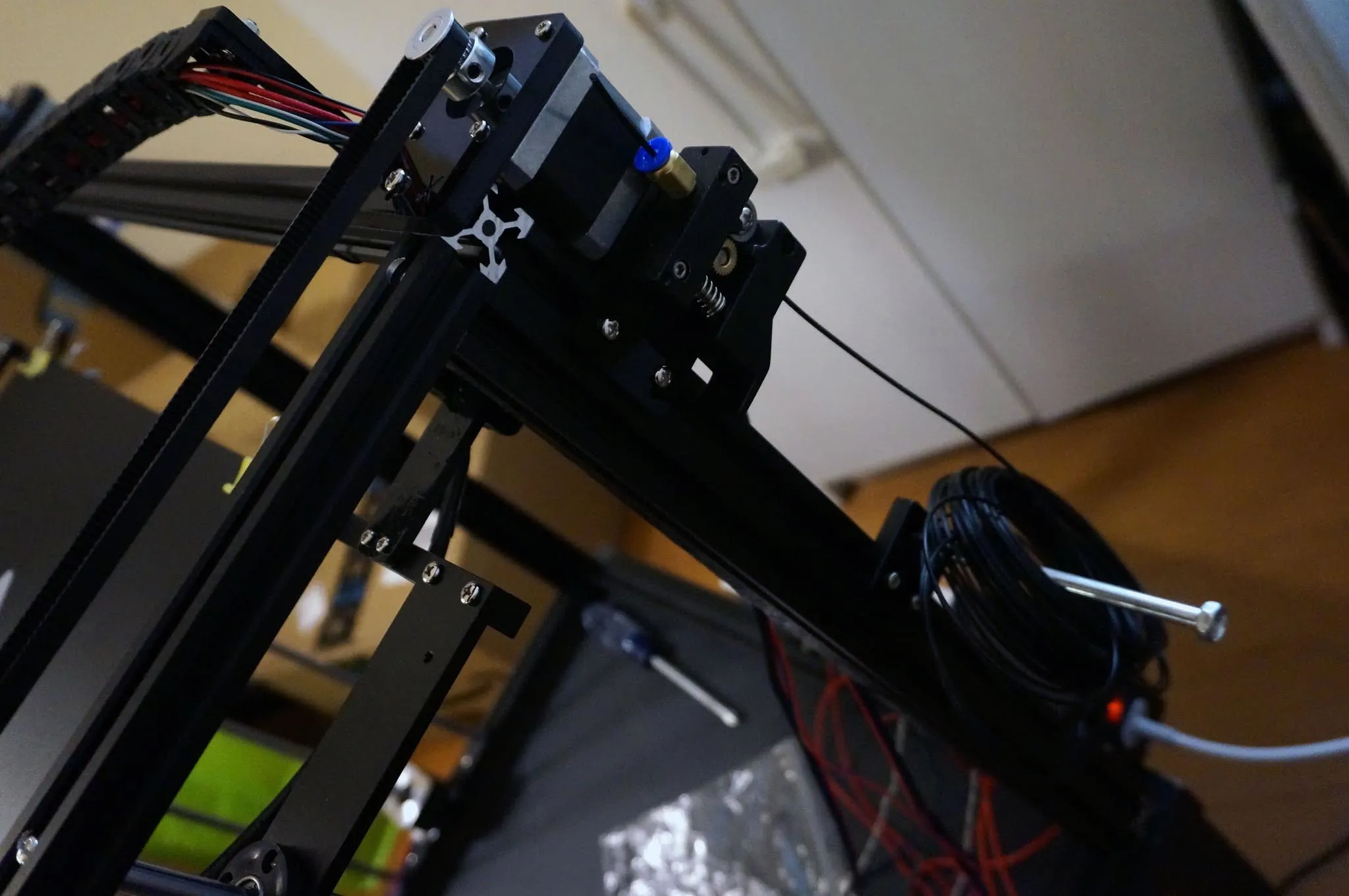
Now let’s install the belts and PTFE tube. The PTFE tube will just press into the fittings. To get an end out, press the plastic tab on the fitting down and pull up on the PTFE tube.
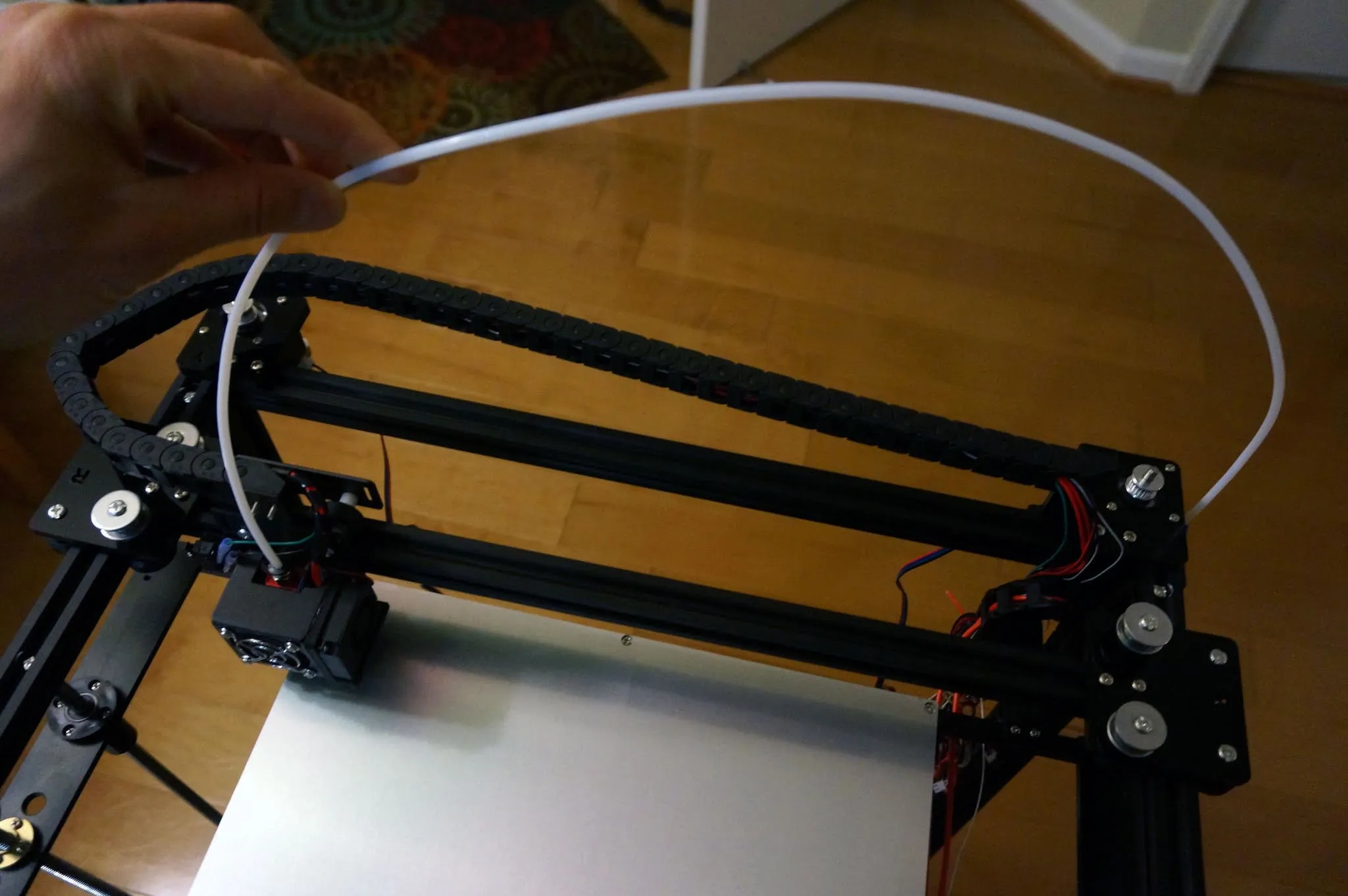
Notice here how the belt is zip-tied to the extruder as well.
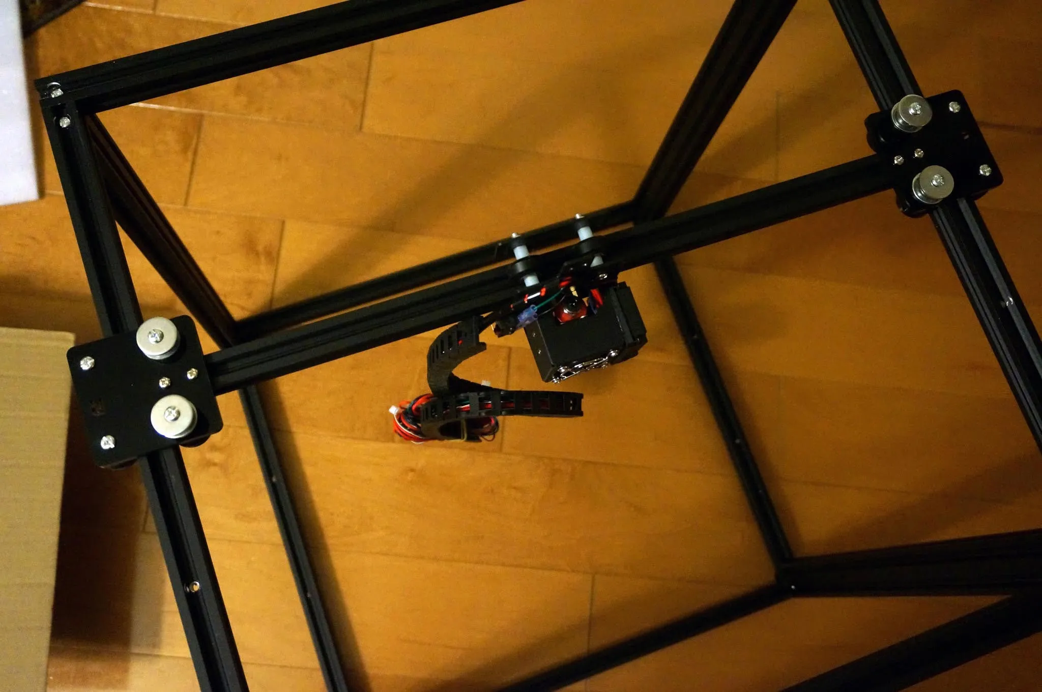
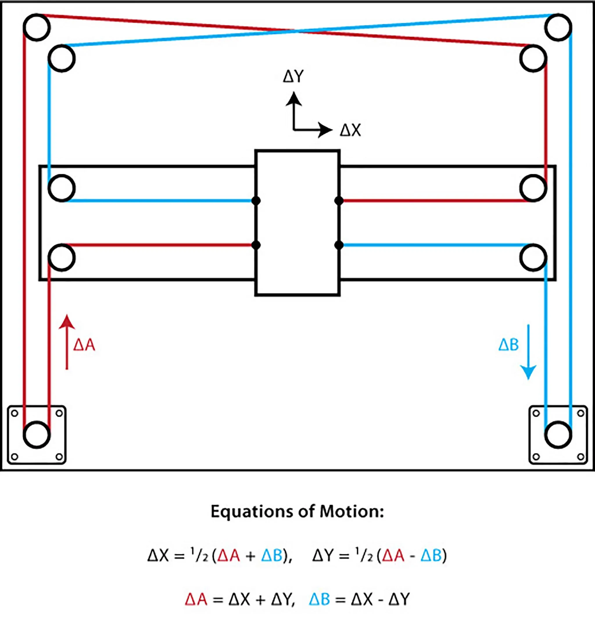
Here is the reference diagram from corexy.com. Note that in our layout, the corner pulleys are stacked vertically, so the belts will not cross.
Loosen T-nut screws on the X and Y motors so they can slide forward; this way, you can slide them back later if you need more belt tension.
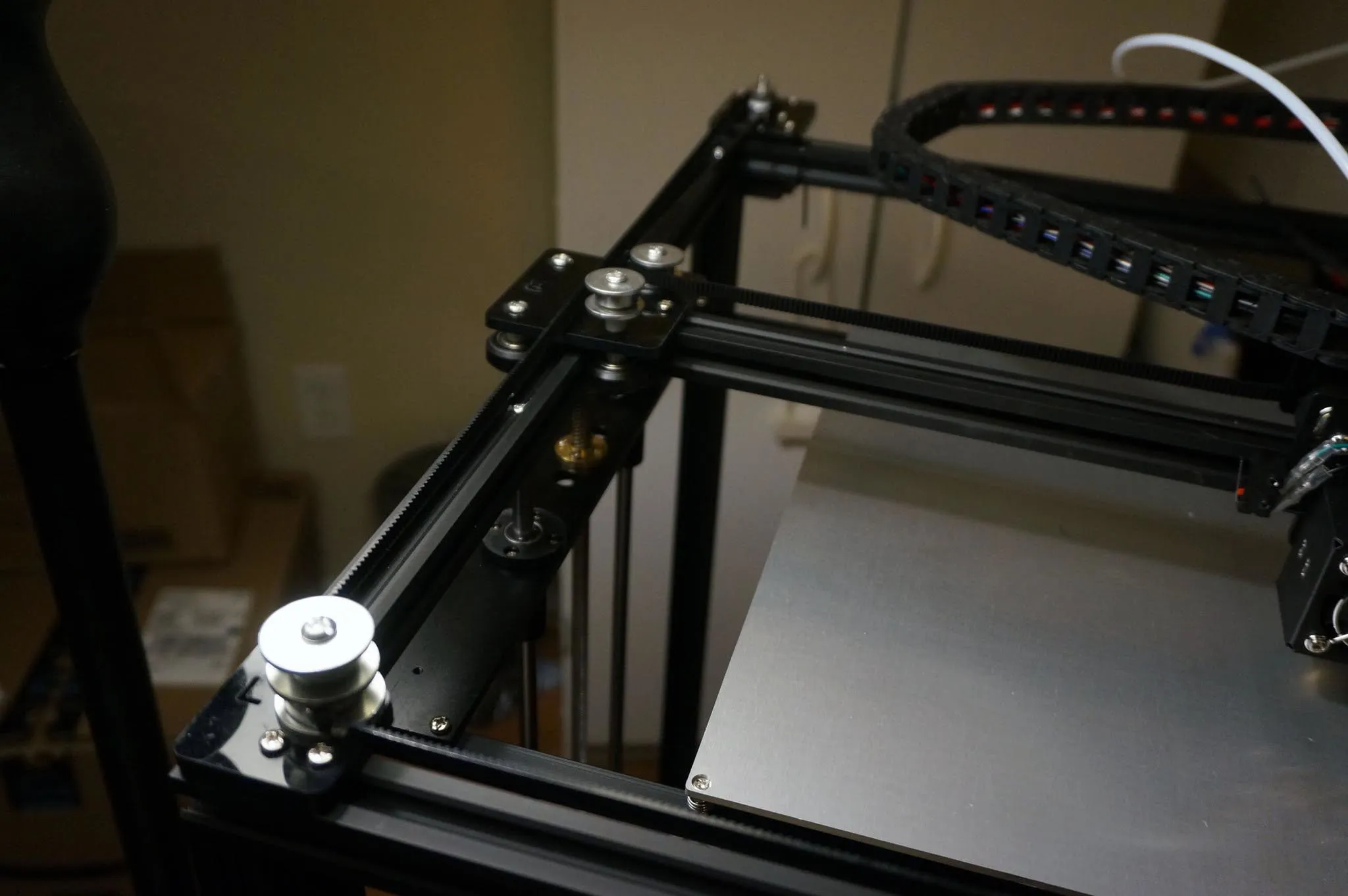
Install one belt at a time. One belt goes on the low set of pulleys and the other will go on the high set of pulleys. Here’s the low set. It doesn’t matter which belt uses the low or high set; as long as the belts don’t cross, they won’t rub.
A single belt attaches to opposite corners of the end effector carriage. Slide the belt on the carriage to the appropriate height, matching the pulley.
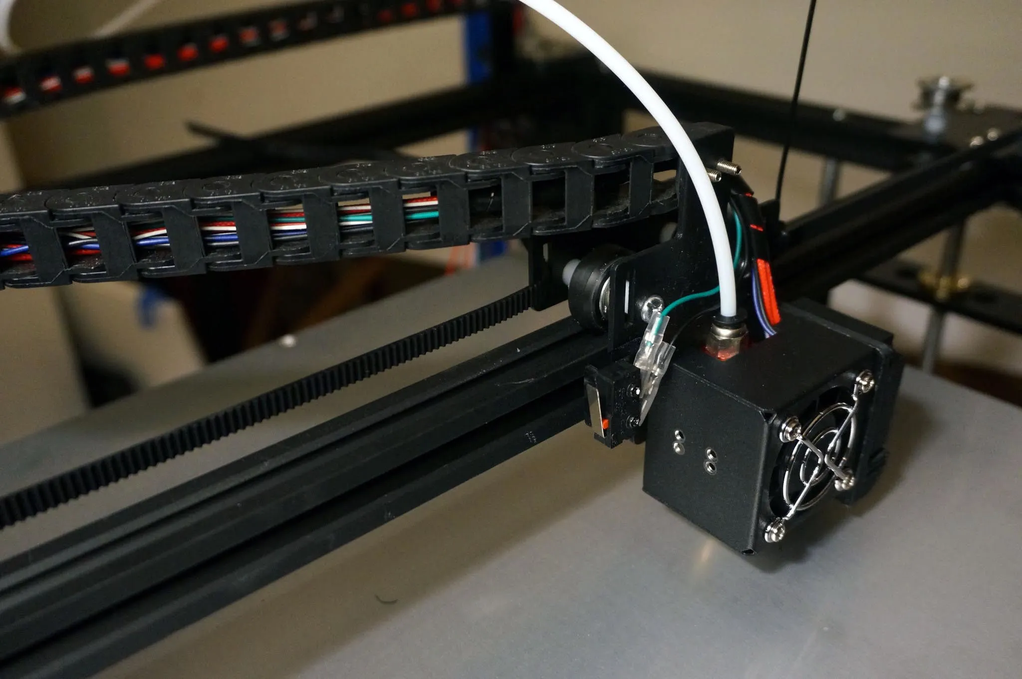
Here, all belts are installed and zip-tied down. Tension should be reasonably tight, but more importantly, the tension should be even.
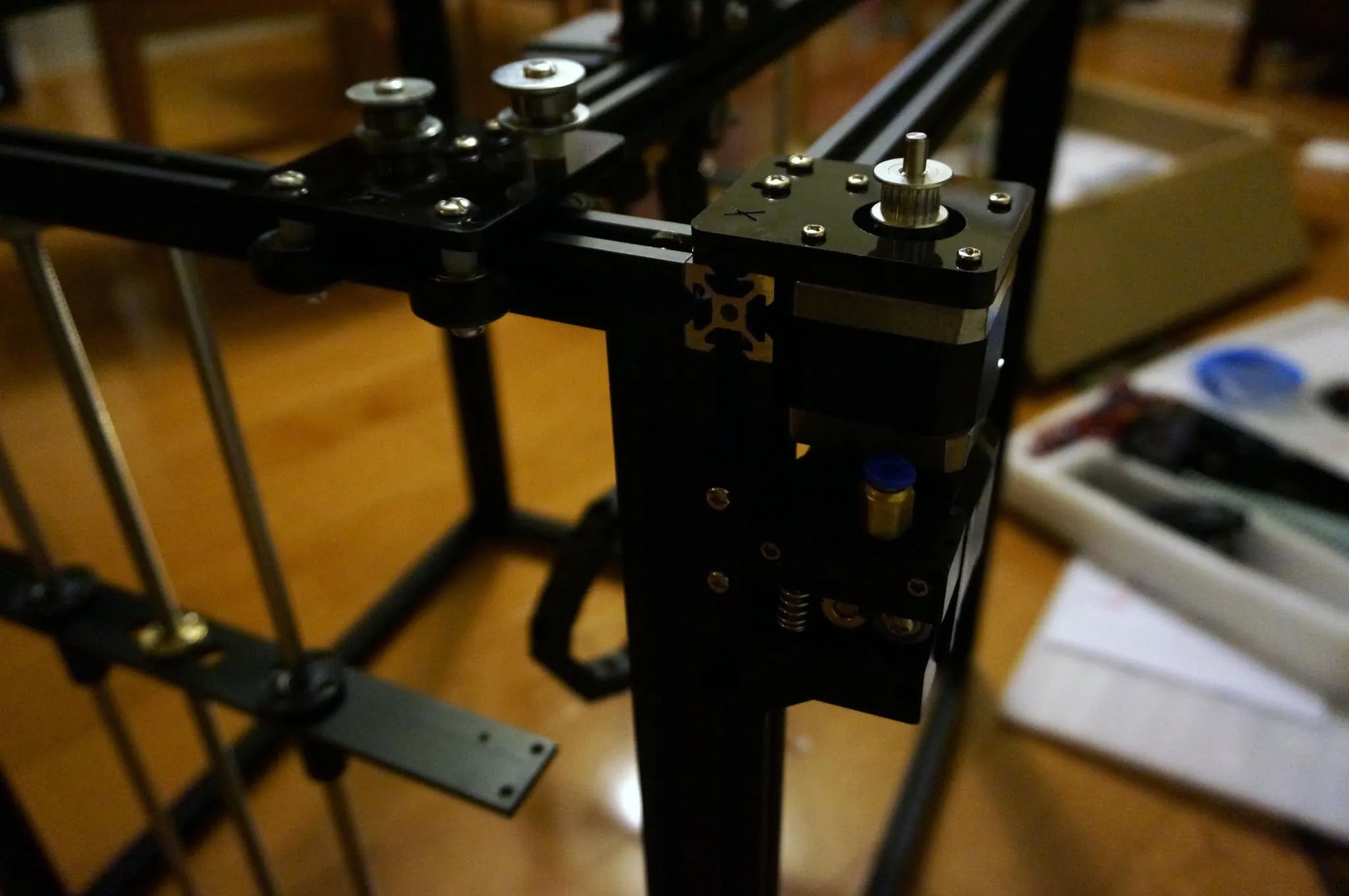
Tighten the gears on the X and Y axis motors as well as tighten the motors into place using the T-nuts and bolts.
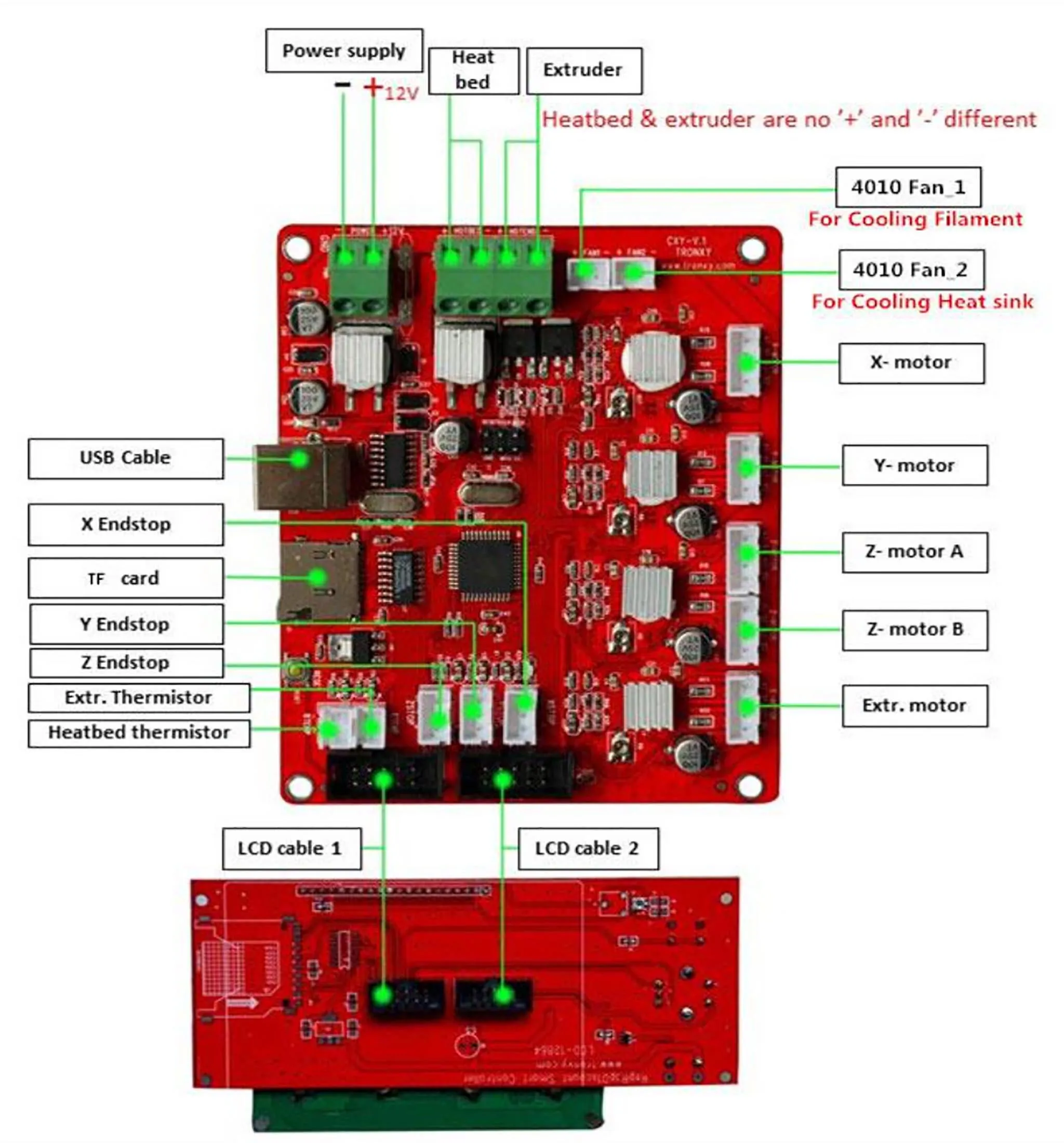
Wiring
Here’s the wiring diagram from the manual.
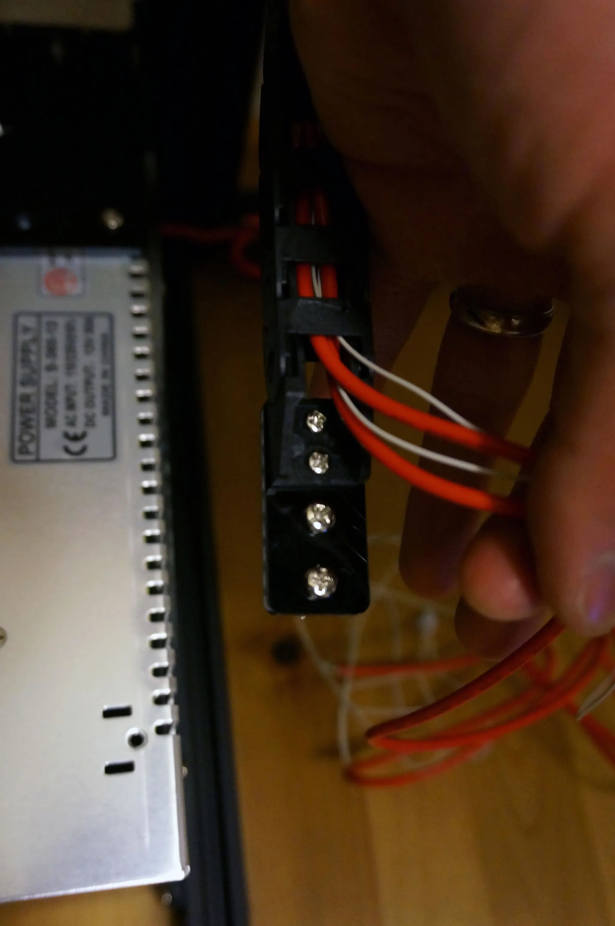
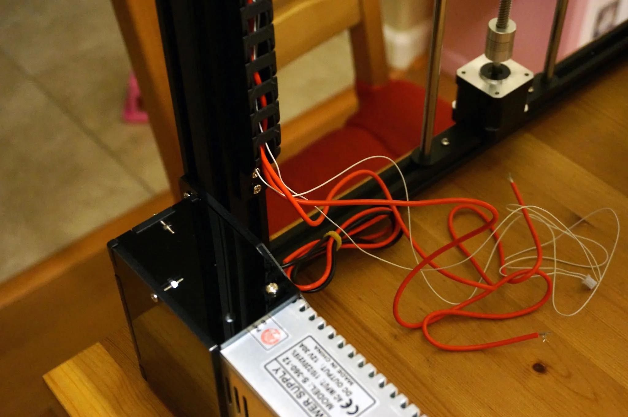
I started by trying to wire everything before putting it in the case, since you won’t be able to get to the screws on the top of the green screw terminals once the case is installed. This turned out to be a huge mess.
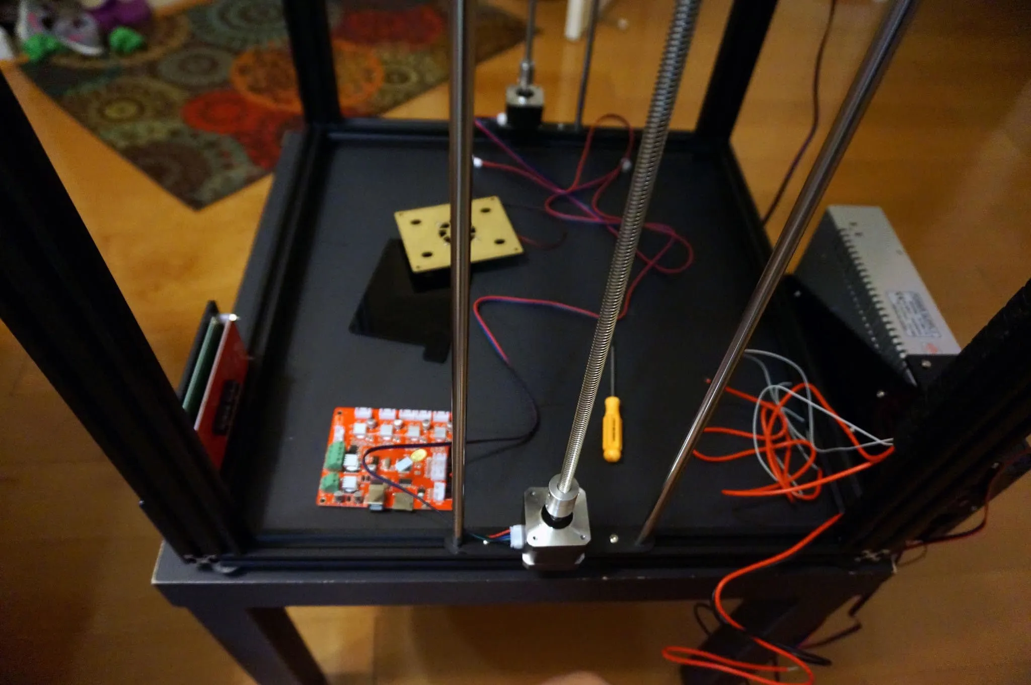
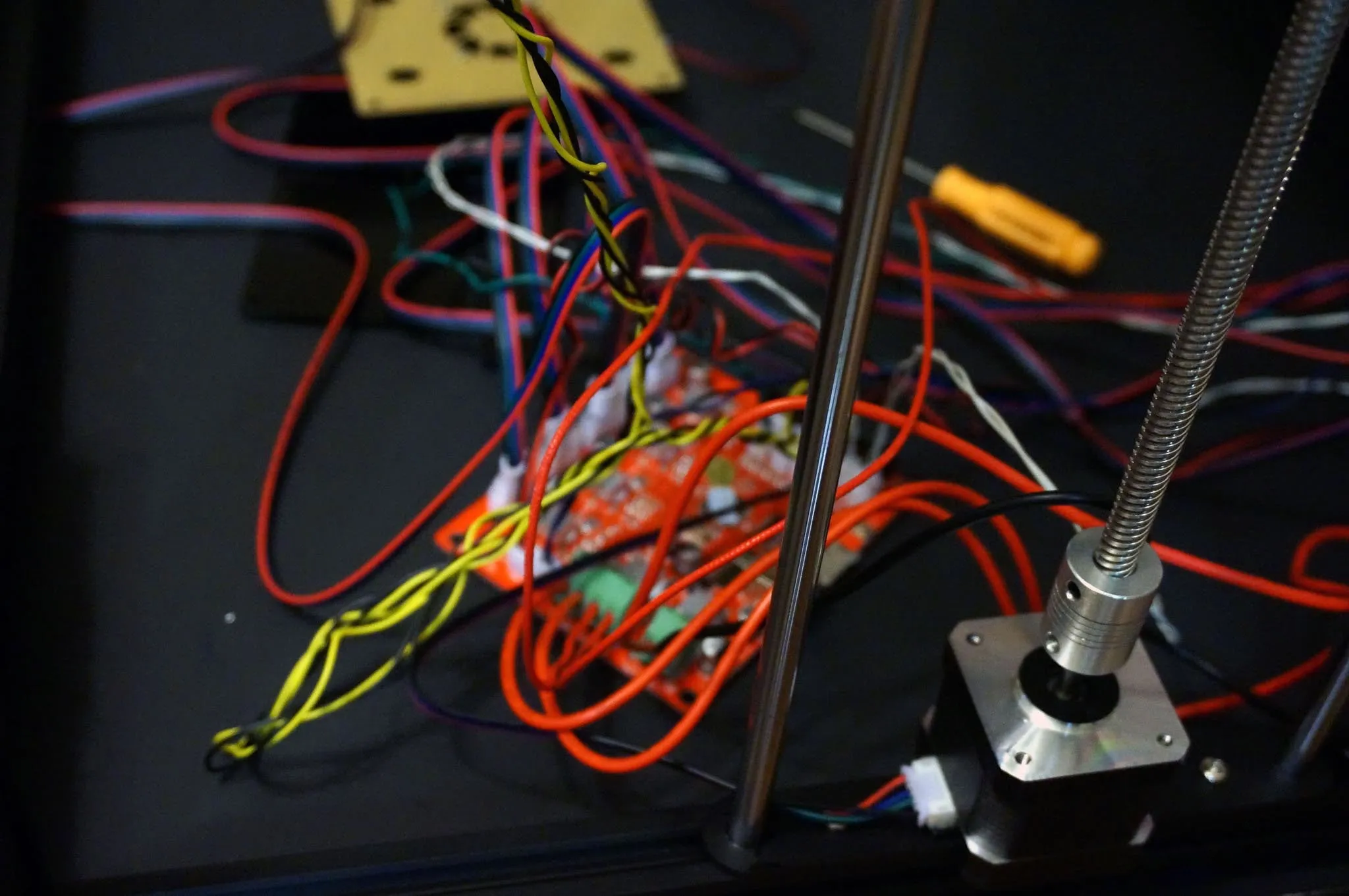
Instead, I suggest you drill some holes in the top acrylic piece (the one with the fan on it) right over the screw terminals, so you can get to them after installing the board in the case.
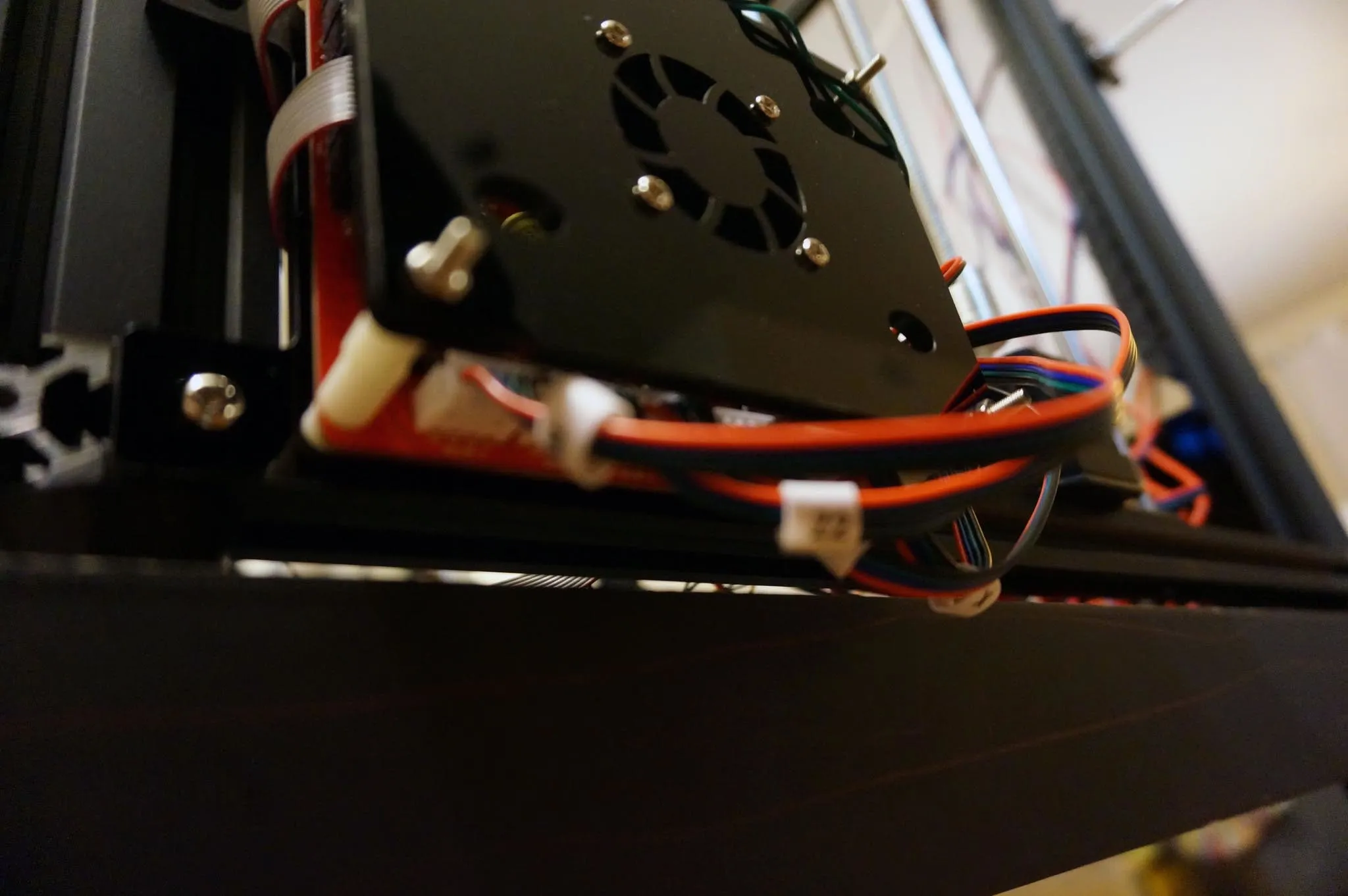
Now install the case and mount the case onto the printer.
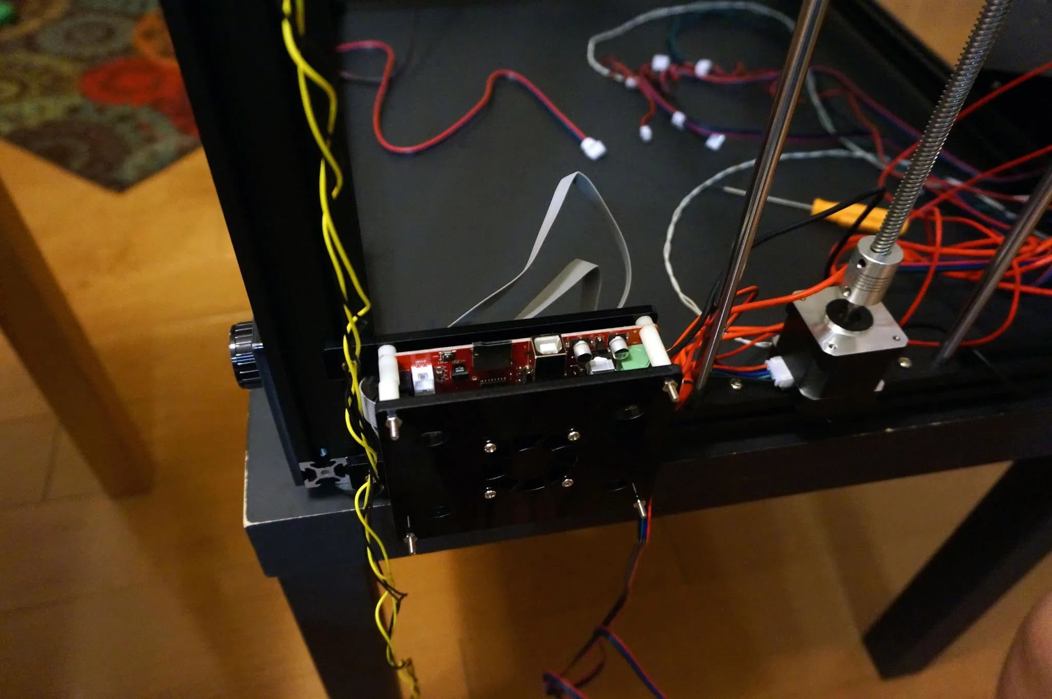
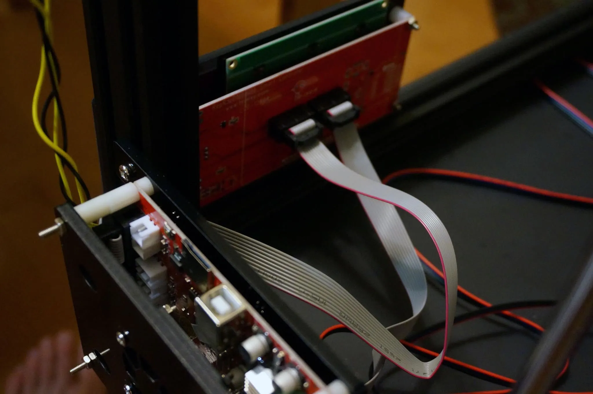
Connect the LCD cables. The top cable goes to the right-most slot in this picture. No problem if you get these backwards, though; just turn off the printer and switch them (you’ll notice the screen lights up but has no text, in which case, just switch the cables).
Connect the end stops (X, Y, then Z).
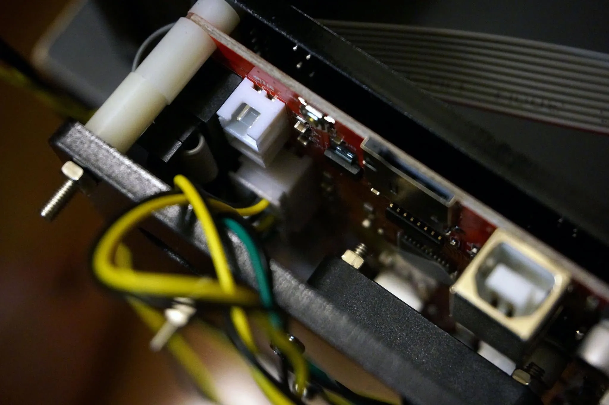
Then connect the white thermistor cables (e.g., temperature sensors), extruder, then bed.
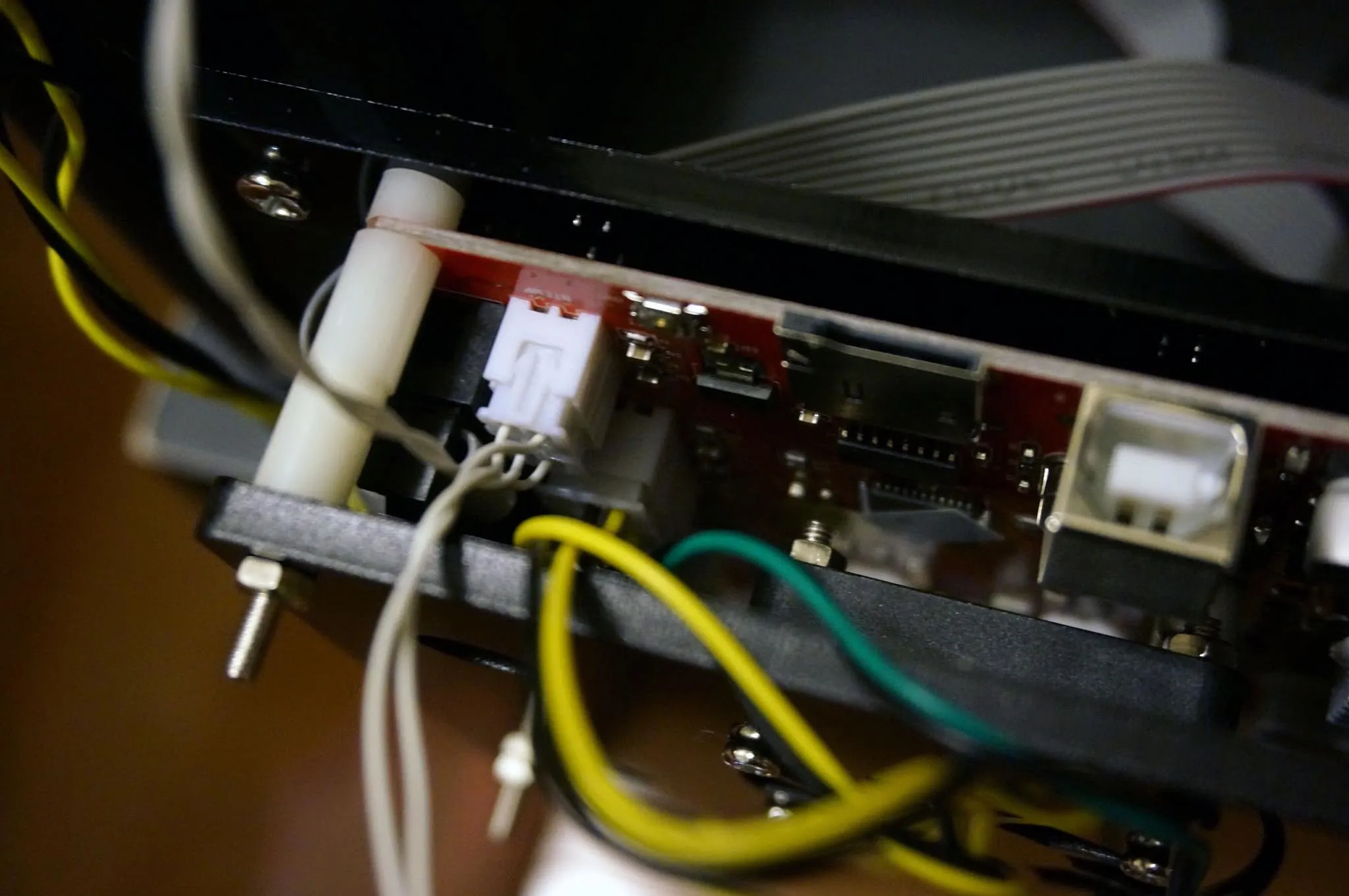
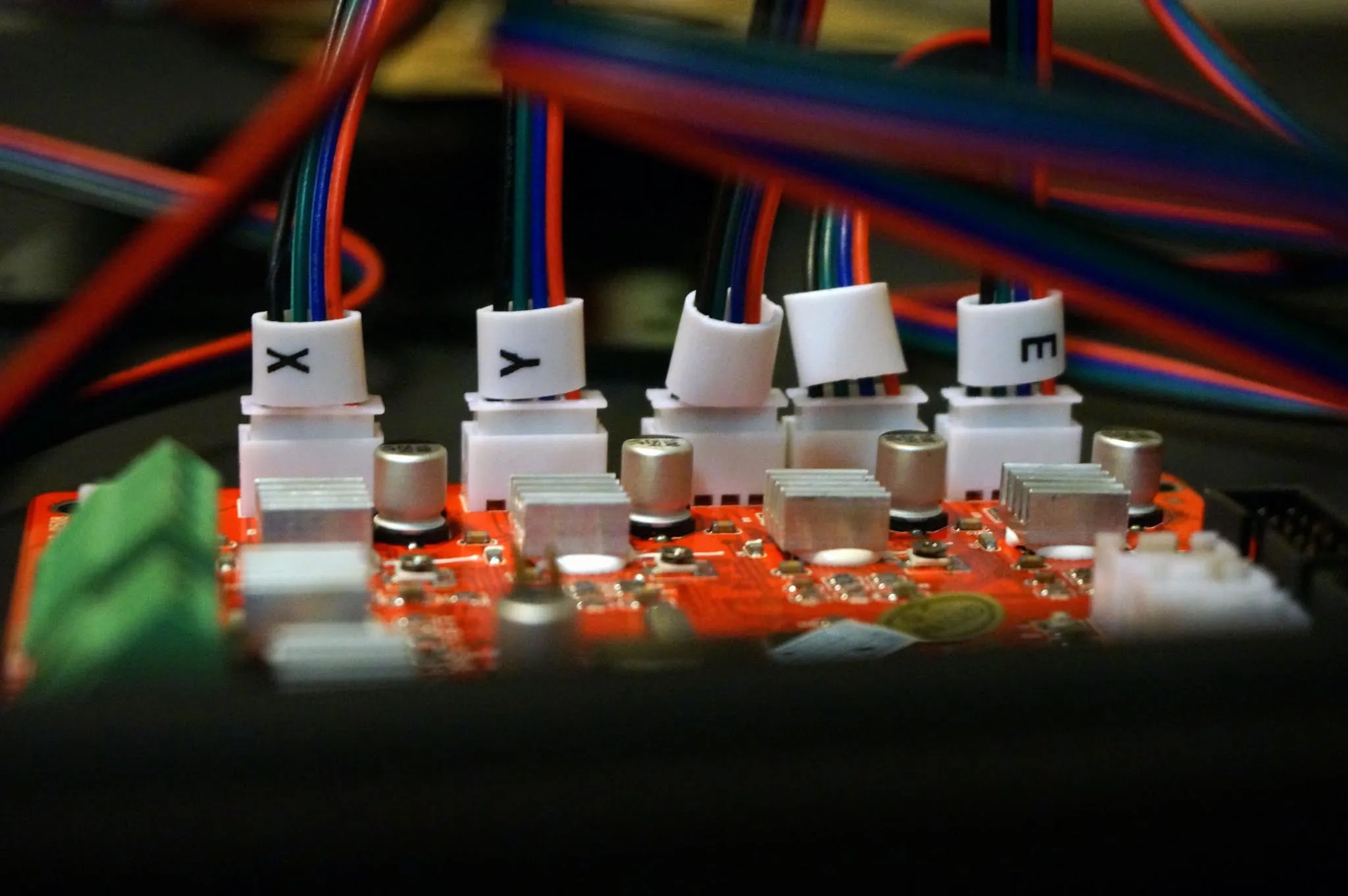
Finally, install all the servo motor cables. The 6-pin sides go into the motors. Note the different lengths and labels.
Firmware Update
I’ve merged Thingiverse user cyberbask’s changes from Google Drive back into Marlin and made a few updates, like fixing the LCD, setting the correct extruder motor calibration settings, and increasing the WATCH_TEMP_PERIOD to avoid the ‘heating failed’ messages.
Download the code from here (click “Clone or Download” then “Download Zip”): /downloads/https-github-com-nathantsoi-ma
Per irrelevantxy on Thingiverse, here is how you install Marlin 1.1.6:
Followed your instruction and successfully updated to Marlin 1.1.6
Just want to say THANKS!

Below is the English instructions for those who need it.

Download and install Arduino IDE 1.8.x

Install Sanguino
In preferences add this URL for additional board manager:
[https://raw.githubusercontent.com/Lauszus/Sanguino/master/package_lauszus_sanguino_index.json](https://raw.githubusercontent.com/Lauszus/Sanguino/master/package_lauszus_sanguino_index.json)
Go to the Board Manager and install the Sanguino.
Select Sanguino and select the atmega1284 16mhz.
Select the port where the printer appears

Install u8glib for OLED Display
Go to the libraries and install the u8glib

Change upload speed
Go to the Arduino Preferences and at the bottom find link to more preference in the directory for "preferences.txt"
Click the link to folder, browse to \packages\Sanguino\hardware\avr\1.0.2\boards.txt
Change the line to following:
sanguino.menu.cpu.atmega1284p.upload.speed=57600
Restart the Arduino IDE (Important)
*4. Change language setting
Change the language setting in configuration file to "En" (English)

Compile and upload the firmware
More on the firmware update here: https://www.thingiverse.com/groups/tronxy-x5s/forums/general/topic:25267
Extruder Calibration
If you’re not using my firmware from above, this is the one thing you’ll want to do to calibrate your printer: measure and set the amount of material extruded as follows to avoid under- or over-extruding.
You’ll notice there is a problem if there are gaps in your print or the walls look like they’re oozing.
We’ll tell the extruder to extrude a certain amount of filament and then compare it to the amount actually extruded.
Mark the filament 150mm above the top of the extruder.
Run this command to extrude 100mm of filament at 90mm/min: G1E100F90
Now measure the mark on the filament to figure out how much was actually extruded.
Run M503 to see your current steps per mm.
new_steps_per_mm = (old_steps_per_mm) * 100 / extruded_length
Set it with M92 E[new steps per mm value here] then run M500 to save.
Watch Tom’s guide here: https://youtu.be/YUPfBJz3I6Y