Setup OrangeLRS with OpenLRSng
Get HAM’d
To legally turn on the 433mhz modules, you need your Amateur Radio License.
If you don’t already have your license, studying is easy with Richard Bateman’s (KD7BBC) hamstudy.org.
Make sure you’re in the FCC database before proceeding.
Wiring
Open up the OrangeLRS TX module and you’ll see the UART headers. Wire these up to your UART-USB module.
- TX on the Orange module goes to RX on the USB adapter.
- RX on the Orange module goes to TX on the USB adapter.
- VCC goes to the 3.3v pin on your adapter. We can’t use 5v here, since the Hope RF module is not 3.3v tolerant.
- Apply 5v to the PWM side of the RX (one of the servo plugs) or the VCC line on the TX(middle pin on the JR module) and any ground.
- You’ll know if you don’t have enough voltage going to the Orange module if it goes into bind mode when connecting via the configurator
- GND goes to ground on your adapter.
Configurator
Install Google Chrome if you don’t have it already.
Download the openLRSng configurator from the Chrome app store. Open the app.
Plug in your UART-USB adapter and click connect.
Transmitter - TX
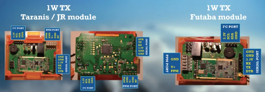
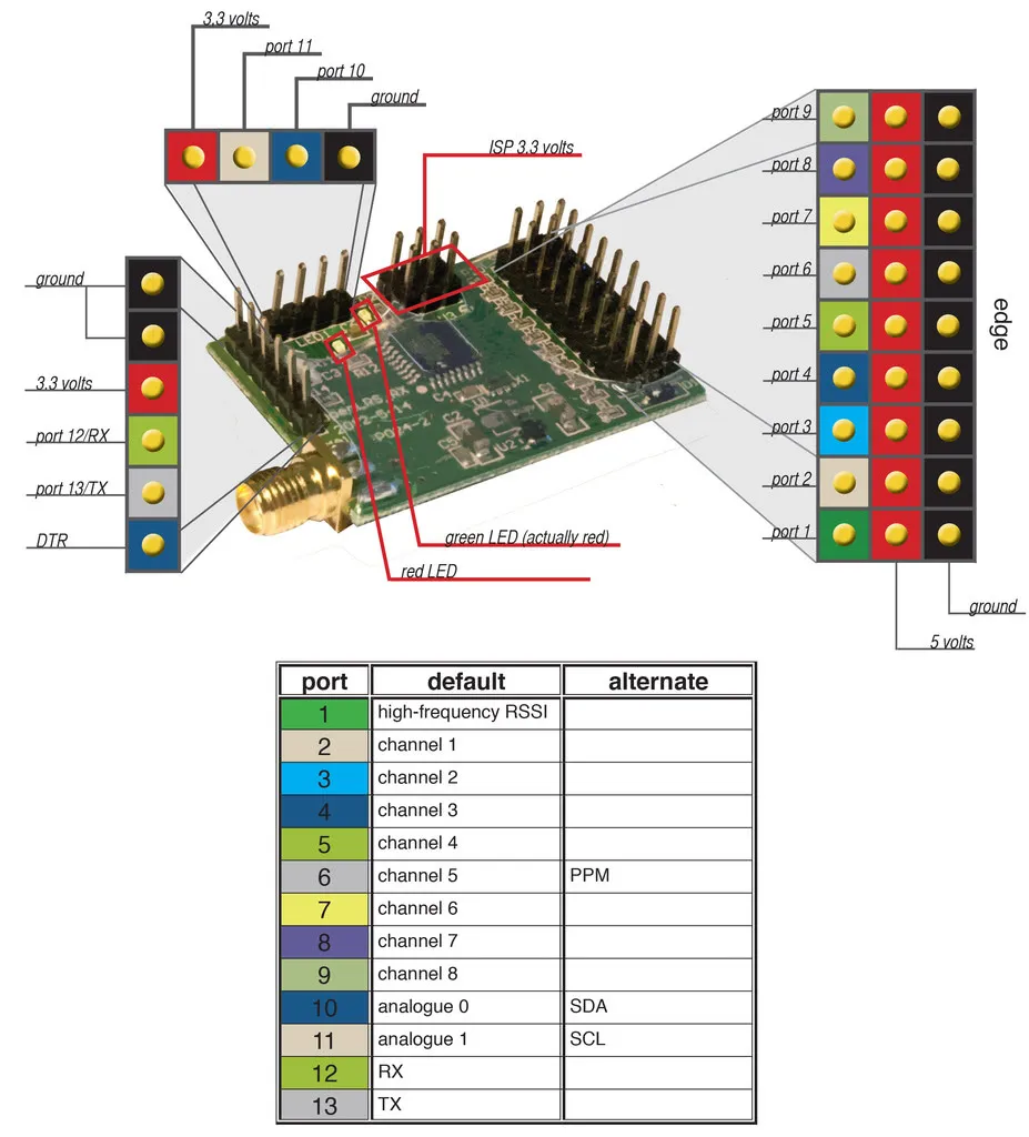
Here are the pinouts for the different OrangeLRS transmitter versions from this great guide.
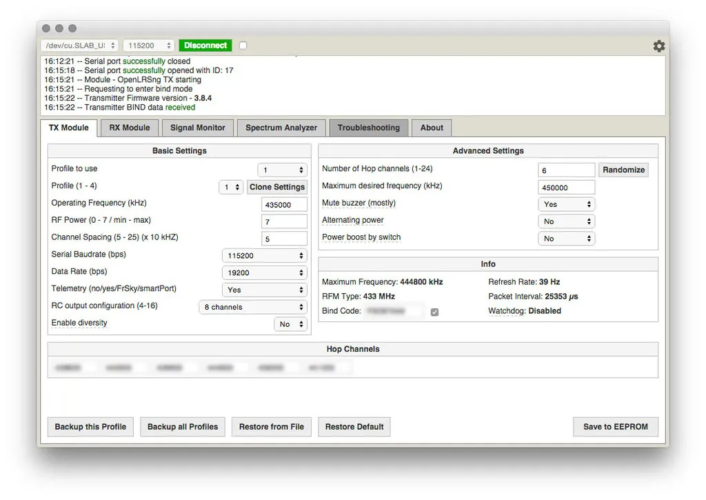
Defaults are mostly good. The only change I made was to set the max frequency to the top of the 70cm band: 450mhz, so we don’t accidentally use any frequencies outside of the band when channel hopping.
Receiver - RX
Switch to the RX tab in the configurator and then power on the RX. The RX does not need to be connected to the computer, just 5v and ground on any of the PWM pins (Where the ESCs/Servos would normal be plugged in)
If the RX is already on when you open the RX tab, it won’t work. Turn the RX of and turn it back on and it should bind.
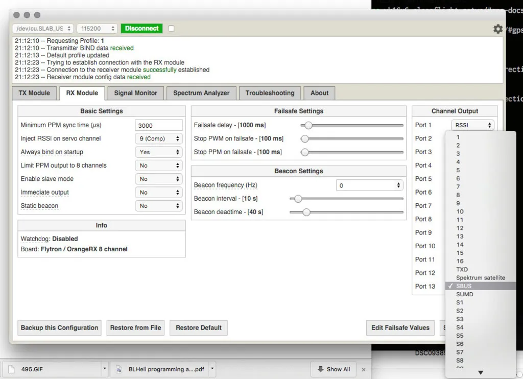
I made the following changes before connecting the RX to my CC3D
Inject RSSI on servo channel - 9 (Comp)
- So we don’t need another wire, the RSSI signal is turned into an output that can drive a servo and injected into the PPM stream, replacing the RC channel of your choice. This channel can then be mapped to an output port. We’ll configure cleanflight for this.
Stop PPM on Failsafe - 100
- So cleanflight knows that the link has failed, don’t wait too long though, we want the flight controller to know exactly when the link has failed. I’ve upped the timeout in Cleanflight to 3 seconds before we failsafe.
Port 6 (CH 5) - PPM
- This appears to be the first port that supports PPM. I’d have to dig into the code to figure out why?
While I’m using PPM at the moment, I plan to hook up Serial RX full telemetry! Look for this in a future post.

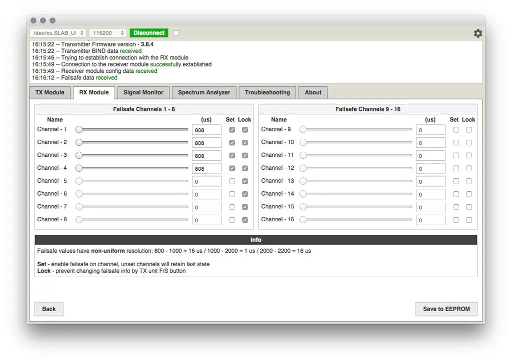
Set your failsafe. You want invalid (< 1000us) data on the first four channels since Cleanflight will know to failsafe if it sees invalid data on any of the first four channels.
Also, note that all other channels have no failsafe set, this is so they continue transmitting their last known positions. In case you are arming with a switch, this is crucial, since you don’t want the switch turning off when signal is lost, thereby disarming the craft unintentionally.
SBUS
OpenLRS supports SBUS (FrSky) and SUMD (Graupner) on pin 13, which is the TX port on most Receivers.
If your OpenLRS won’t boot
No worries, just re-load the bootloader! I’ve had to do this after a really hard crash. Also, note that there is lots of info out on the interwebs warning against using 5v to program the Tx/Rx as the RFM22b Hope RF module is not 5v tolerant, but don’t worry, you’re probably fine even if you’ve plugged in a 5v USB/UART adapter.
Download the latest releases from openlrsng.org/releases, you want 433.zip
Download winavr
When connecting your USB/UART adapter, always ensure it is on 3.3v mode and not 5v mode as the HopeRF module is not 3.3v compatible. You can (and should) apply 5 volts to the BEC (PWM output side, the pins for all the channel outputs), to power the board externally.
Original Fuses were: Low: F7, High: D8, Ext: 07
avrdude -b 19200 -c avrisp -p m328p -P COM3 -v -e -U lfuse:w:0xF7:m -U hfuse:w:0xD8:m -U efuse:w:0x07:mNote that the OpenLRSng readme states fuses should be set to: Low: FF, High: DE, Ext: 05 However, the original fuses worked fine for me, so I didn’t change them. If you did want to update the fuses, you would use:
# connect everything and test that comms work, you should see something like
#   avrdude.exe: warning: cannot set sck period. please check for usbasp firmware update.
#   avrdude.exe: AVR device initialized and ready to accept instructions
#   Reading | ################################################## | 100% 0.03s
#   avrdude.exe: Device signature = 0x1e950f
#   avrdude.exe: safemode: Fuses OK
#   avrdude.exe done.  Thank you.

# Read fuses
avrdude -b 19200 -c avrisp -p m328p -P COM3 -v

# Program fuses
# note -e erases the chip and -v is for verbose
# if you're curious, http://www.engbedded.com/fusecalc
avrdude -b 19200 -c avrisp -p m328p -P COM3 -v -e -U efuse:w:0x05:m -U hfuse:w:0xDE:m -U lfuse:w:0xFF:m

# It might also work with, which limits the bootloader size to 256 words instead of 2048 words
#  http://www.hackersworkbench.com/intro-to-bootloaders-for-avr
#  avrdude -b 19200 -c avrisp -p m328p -P COM3 -v -e -U efuse:w:0x05:m -U hfuse:w:0xDA:m -U lfuse:w:0xFF:m
Now install the bootloader and OpenLRSng:
# Copy RX-3-bl.hex into the folder your working from or the number for your board type. -bl.hex files include the bootloader, which we want
#  // Enable one of the lines below (remove leading //)
#  //#define BOARD_TYPE 0 // 0 = Flytron OpenLRS M1 Tx Board (not verified)
#  //#define BOARD_TYPE 1 // 1 = Flytron OpenLRS M1 Rx Board as TX (not verified)
#  //#define BOARD_TYPE 2 // 2 = Flytron OpenLRS M2/M3 Tx Board / OrangeRx UHF TX
#  //#define BOARD_TYPE 3 // 3 = Flytron OpenLRS Rx v2 Board / OrangeRx UHF RX / HawkEye UHF RX (RX and TX supported)
#  //#define BOARD_TYPE 4 // 4 = OpenLRSngTX / HawkEye UHF TX
#  //#define BOARD_TYPE 5 // 5 = OpenLRSngRX-4/6ch (DTF UHF/HawkEye) (RX and TX supported)
#  //#define BOARD_TYPE 6 // 6 = DTF UHF/HawkEye DeluxeTX (Atmega32u4)
#  //#define BOARD_TYPE 9 // 9 = BroversityRX

# program bootloader
avrdude -b 19200 -c avrisp -p m328p -P COM3 -v -e -U flash:w:RX-3-bl.hex
Note, if you get a stk500_getsync() error, try pressing the reset button on your ISP arduino (the one you flashed with the ArduinoISP code) and running avrdude again
Reading
This is a great guide on improving transmitter performance
Checkout the Settings Guide for a full description of all the configurable params