Rctimer OZE32 / RTFQ Flip32 AIO Integrated Flight Controller Review and Setup
This article is an in-depth review and setup guide for the Rctimer OZE32 aka RTFQ Flip32 AIO.
Overview
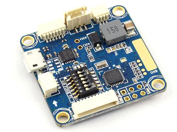
Rctimer has just released a new flight controller (FC), the OZE32. This flight controller has all the hardware on a normal Naze32, plus the two components I add to all of my multi-rotors — a current sensor and MinimOSD. Also included is a switch that changes the connection of the on board CP2102 UART/USB adapter between the flight controller and the OSD. This means you don’t need to buy an external CP2102 USB/UART adapter.
A current sensor measures the exact amount of battery that has been used and the OSD displays this information as text overlaid on your video feed. Here’s an example video I recorded with my Go FPV Goggles app for Android.
Useful stats shown on the OSD are RSSI, Voltage, mA in use and total mAh, flight mode and an artificial horizon.
Updates
April 2016
Airbot now carries version 1.03 of the OZE32 which has an better MAX7456 which is less sensitive to voltage spikes, better power management with 3 LDOs and the IMU interrupt is now connected to the STM32 for gyro sync!
Also, Airbot has a F3 AIO flight controller available as well, the Flip32 F3 AIO Lite.
January 2016
The BeeRotorF3 flight controller and it’s companion PDB with a build-in current sensor are the latest AIO setup by Rctimer. With this package you get a minim OSD and an F3 processor in a tiny package. Though the F3 processor runs at the same speed as the F1, the F3 has a floating point coprocessor, meaning you can run the LuxFloat pid controller at 1khz, which is a huge advantage as Boris’ BetaFlight firmware has an amazing default tune on LuxFloat.
Read the
If you are interested in a FPV racing new quad, but don’t want to research and build from scratch, you should checkout the Victory230 from Rctimer, which will be running the BeeRotorF3. This thing is a hyper-performant beast with amazing value. Plus, it’s ready to fly.
December 2015
The first two versions of the OZE32 suffered from power management issues that could cause the OSD to cut out when plugging in a battery. Though possible, it is highly unlikely the OSD would cut out while in flight. This has been fixed in version 1.02.
Version 1.02 is available from ready to fly quads or myairbot.com. Rctimer will carry the F3 version noted above, as a replacement.
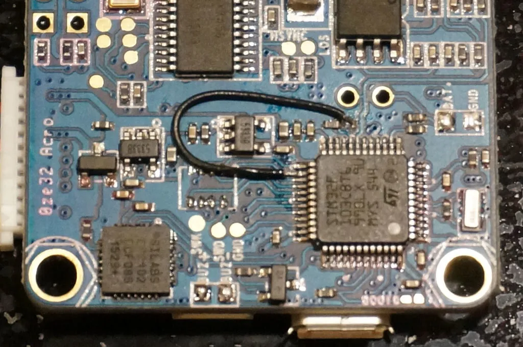
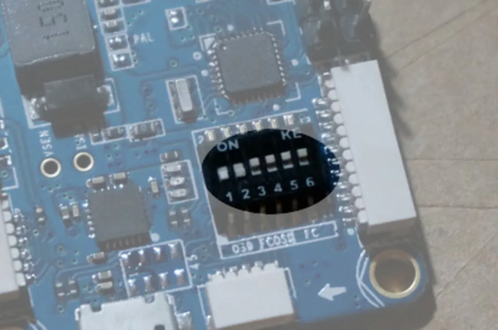
If you already have an OZE32 and are wondering what version you have, you can identify it with the guide below.
Also, if you have an older version don’t be afraid to run with in, all the suppliers know about the issues, so if the OSD does go outit’s easy to drop in a replacement if you run into trouble with aon o
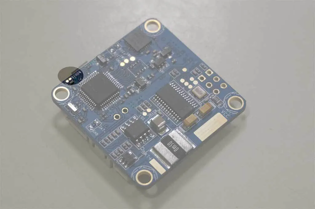
Identifying your board
There are currently 3 iterations of the OZE32 / FLIP32 AIO in the wild.
| Image | Description |
|---|---|
| (Image Missing: /img/blog/oze32/parts/nylon-m3-nut.jpg) | Assembled with Nylon m3 nuts |
| (Image Missing: /img/blog/oze32/parts/nylon-m3-bolt.jpg) | And Nylon 12mm x M3 Bolts |
| (Image Missing: /img/blog/oze32/parts/xrotor-20a.jpg) | xRotor 20a ESCs flashed w/ BlHeli |
| (Image Missing: /img/blog/oze32/parts/be1806-black.jpg) | DYS BE1806 2300kv Motors |
| (Image Missing: /img/blog/oze32/parts/dal-5045.jpg) | Dal 5045 Bullnose |
| (Image Missing: /img/blog/oze32/parts/4s-2200.jpg) | 4S 2200mah Battery |
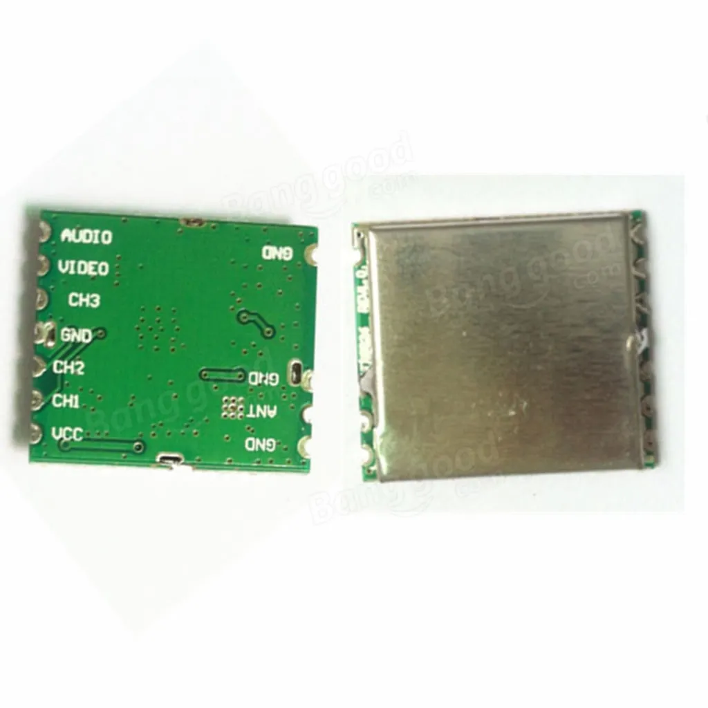
| (Image Missing: /img/blog/oze32/parts/400mw-vtx.jpg) | 5v Boscam 400mw Micro Video Transmitter |
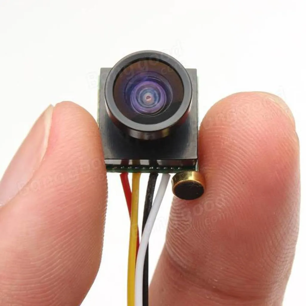
| (Image Missing: /img/blog/oze32/parts/1g-camera.jpg) | 5v 600TVL 1 gram CMOS camera |
| (Image Missing: /img/blog/oze32/parts/9x.jpg) | 9x Transmitter |
| (Image Missing: /img/blog/oze32/parts/443-tx.jpg) | 433mhz LRS Transmitter Module |
| (Image Missing: /img/blog/oze32/parts/443-rx.jpg) | 433mhz LRS Receiver Module, set to PPM injecting RSSI on ch 9 |
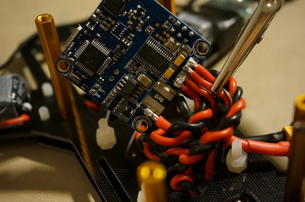
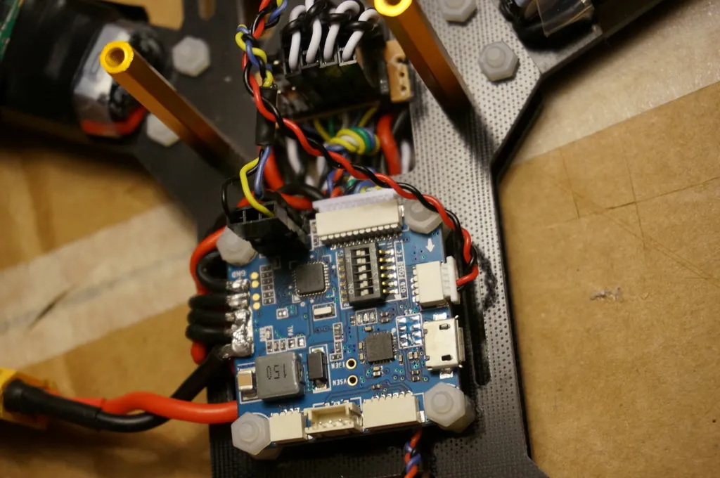
Power
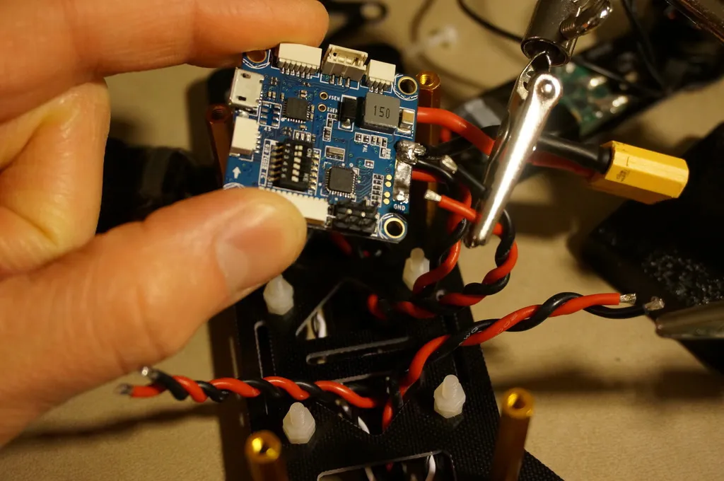
I started by soldering a little red JST connector to the large VCC and GND pads. I haven’t soldered it on in this picture yet, but the XT-60 for the battery will be
connect to bat+:
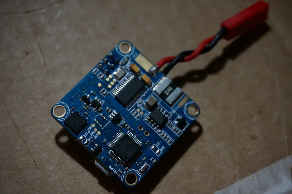
This JST plug will connect this to the power distribution board (PDB) on the quad frame. This will allow us to choose if we want to power the MinimOSD (by plugging a battery into the JST directly) or the flight controller and ESCS (by plugging a battery into the XT-60 and plugging the JST into the PDB).
Alternatively, if you don’t have a PDB, you could solder your ESC power lines straight to the big VCC and GND pads on the flight controller.
Connect IMU Interrupt Pin
Connecting the IMU pin takes some fine soldering skill. Anyone can do it with some patience and a normal iron, but proceed at your own risk or skip to the ESCs section, if you’d rather not tempt fate. Also, connecting this pin will only help if you’re flying BetaFlight (which you should be), CleanFlight doesn’t have Gyro Sync, which is the whole reason we’re connecting the pin.
I’ve flown one quad with the IMU pin soldered and one without the pin connected. The one without the connection flies fine, so don’t feel like you have to do this, but if you do, it will feel a bit more locked in.
You’ll notice in the configurator that if this IMU pin is not connected your looptime will be around 1100 and around 1000 if you choose to solder the connection. The big difference though is not 100ms in loop time, but reducing aliasing.
Update (Feb 2016): The BetaFlight code has changed such that the loop time will be at or near 1000 even if the IMU pin is not connected. This reduces the impact of aliases when gyro sync is not available. This means that connecting the IMU pin no longer makes a significant performance difference. Since I have fried a chip connecting the IMU pin, I suggest you skip this step as the risk is not worth the payoff. Jump to the section on ESCs.
Remove the solder mask from the IMU interrupt pin via. I used the tip of a pin:
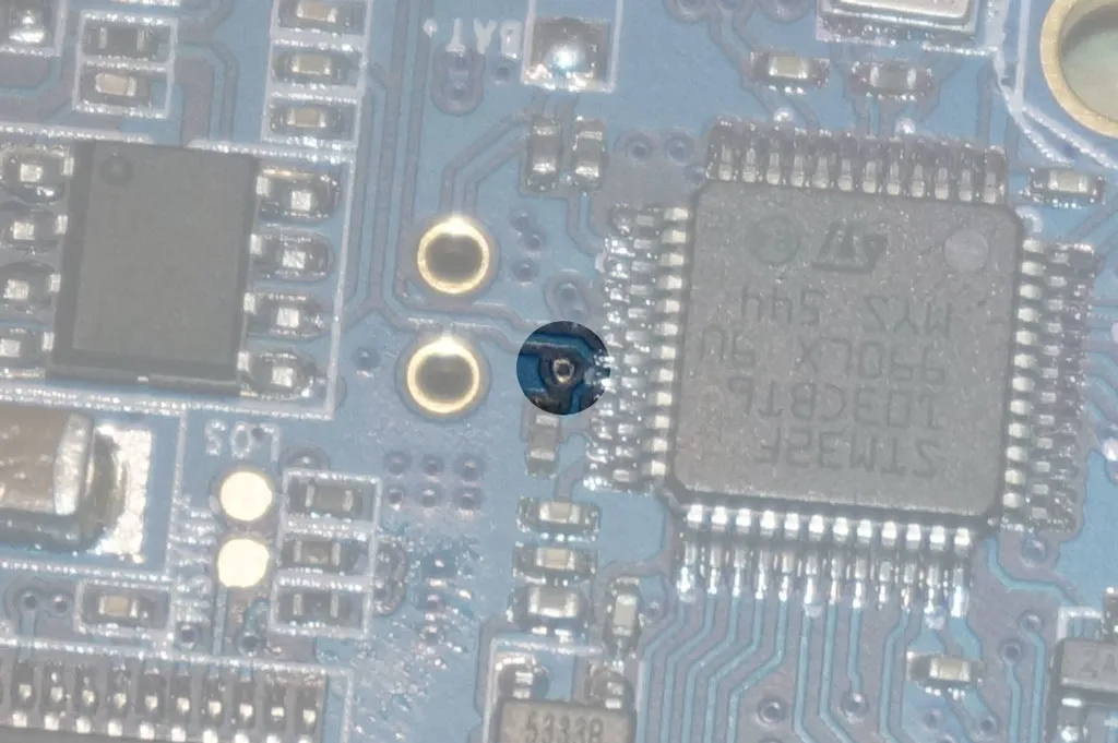
Optionally, use a flux pen to tin the pad you just exposed, get a small blob of solder on your iron then touch the via. Solder should flow into the via and tin the pad.
Cut, strip and tin a small guage wire then touch the wire to the tinned via and then touch your iron. It should flow together and stick nicely.
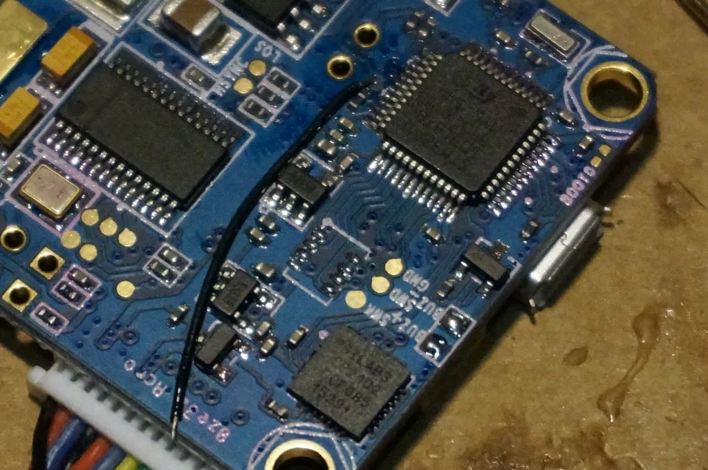
Flux the STM32 pin with your pen, tin your wire then hold the wire against the STM32 pin. Touch your tinned iron to the wire and let the solder flow.
Don’t worry if you get a little extra solder on something, just use some solder wick to clean up then wipe everything down with rubbing alcohol.
ESCs
First though, flash your ESCs with BlHeli and the BlHeli bootloader so you can configure them via pass through programming after you’ve assembled your copter.
Follow the guide here to
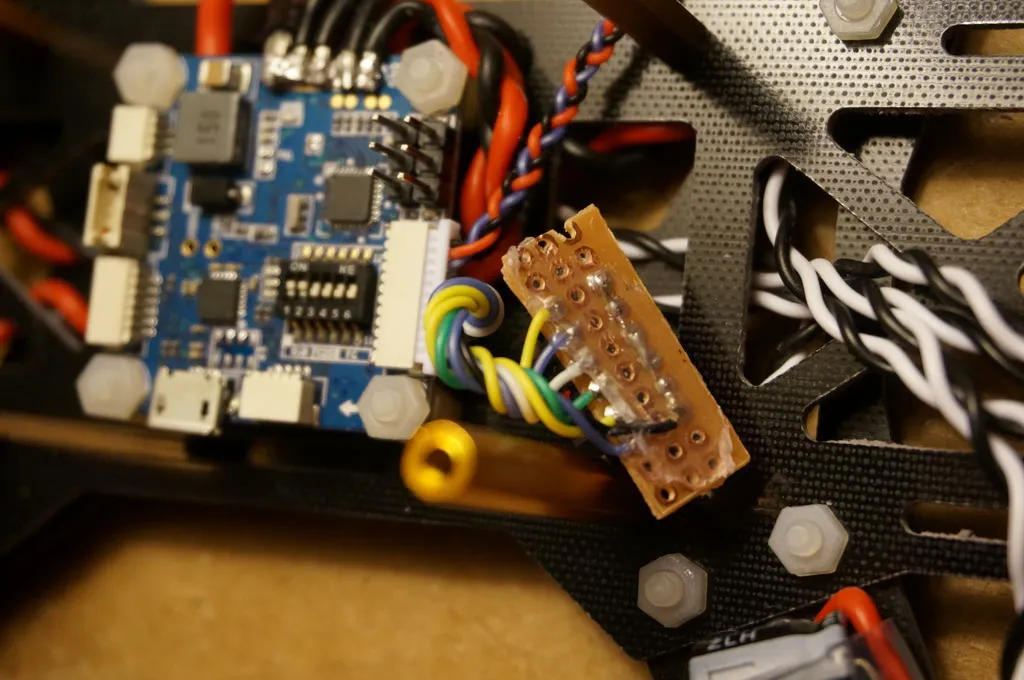
Twist your wires first, open loops between ground and power create magnetic fields which could throw off your magnetometer, if you have one (or decide to add one later via the I2C port).
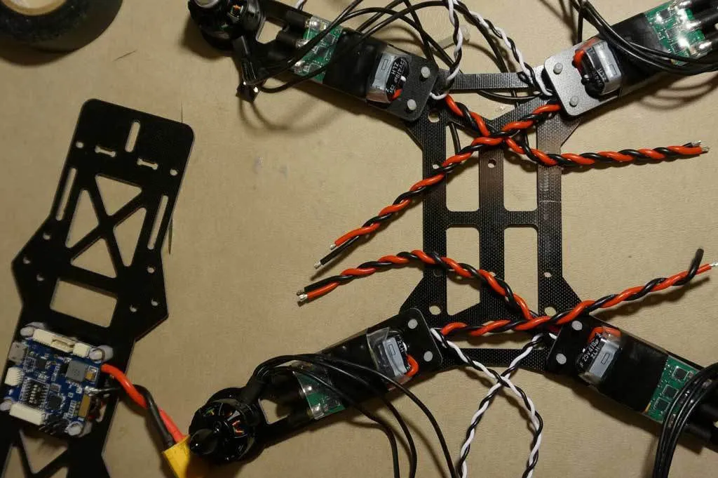
It helps to use some helping hands.
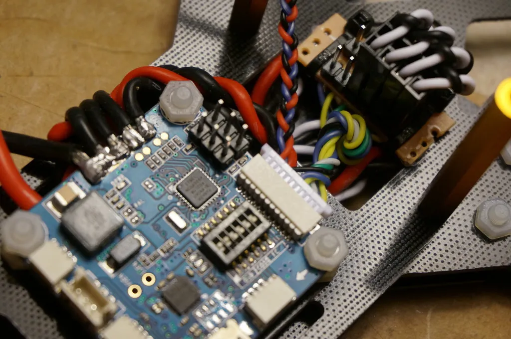
Tin the GND and VCC pads with some solder. Tin the wires and then heat the wire and hold it against the board. As soon as you see it all liquefy, remove your iron and wait a second for it to cool.
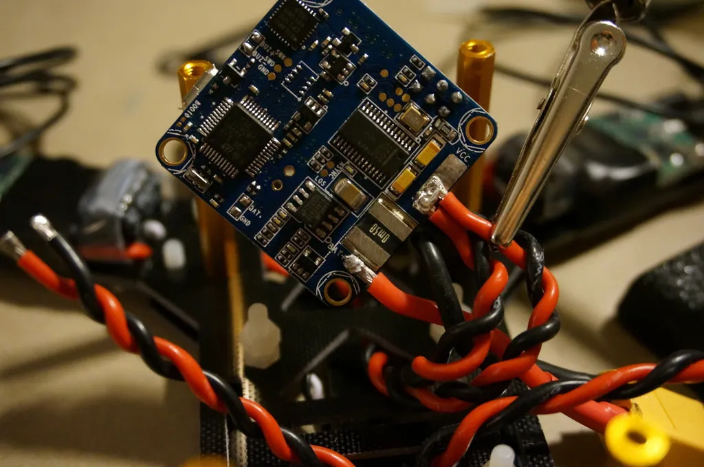
They’ll all fit and there is enough mass so that soldering on another doesn’t release the already-attached wires.
Done! The wires fit perfectly.
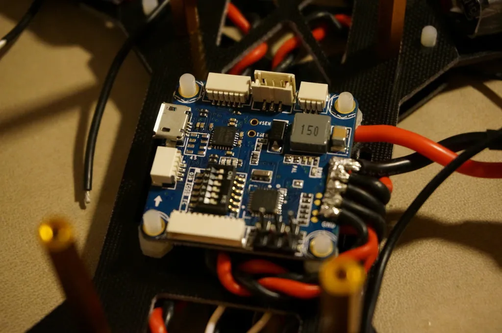
Connect your RX as described in the section on Serial Ports. I’m using PPM, so I’ll use this plug.
Wires look neater braided.
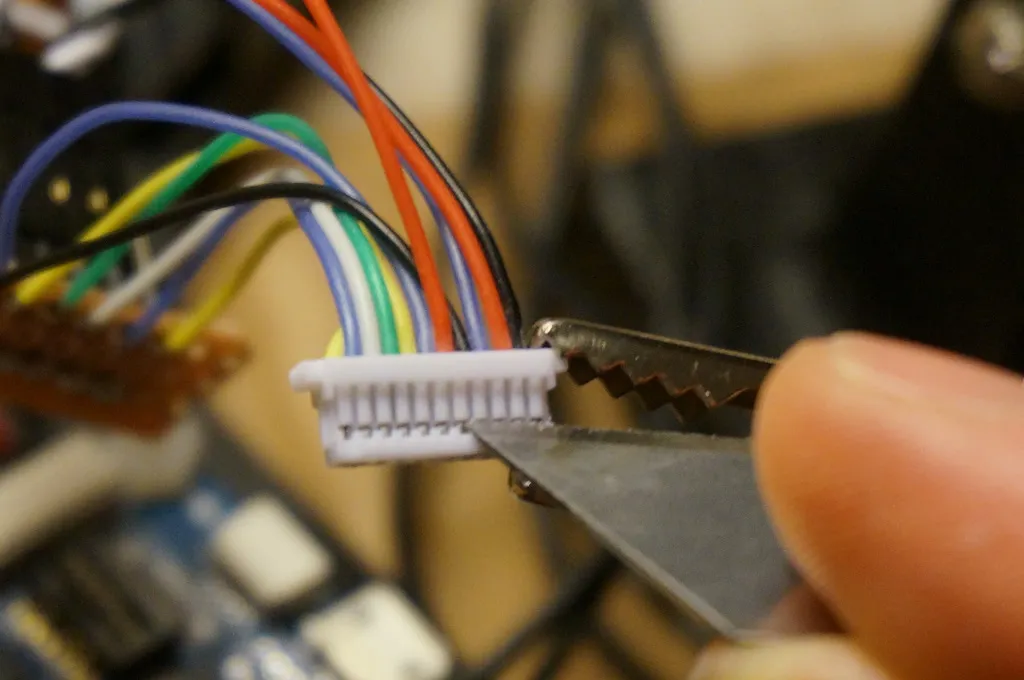
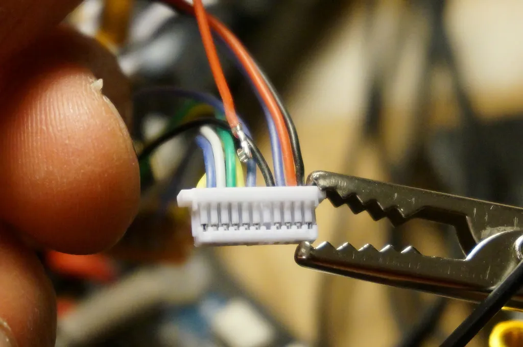
I also removed the extra VCC IN pin from the JST plug. Pop up the tooth with an blade and pull out the wire. Hold onto it though, you can always put it back in if you need it later.
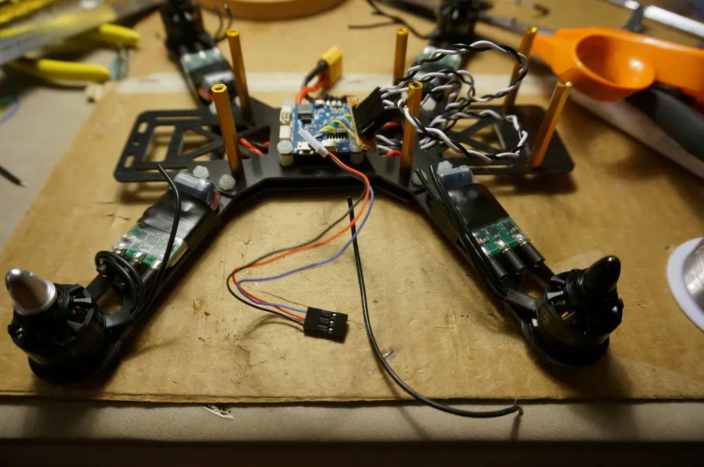
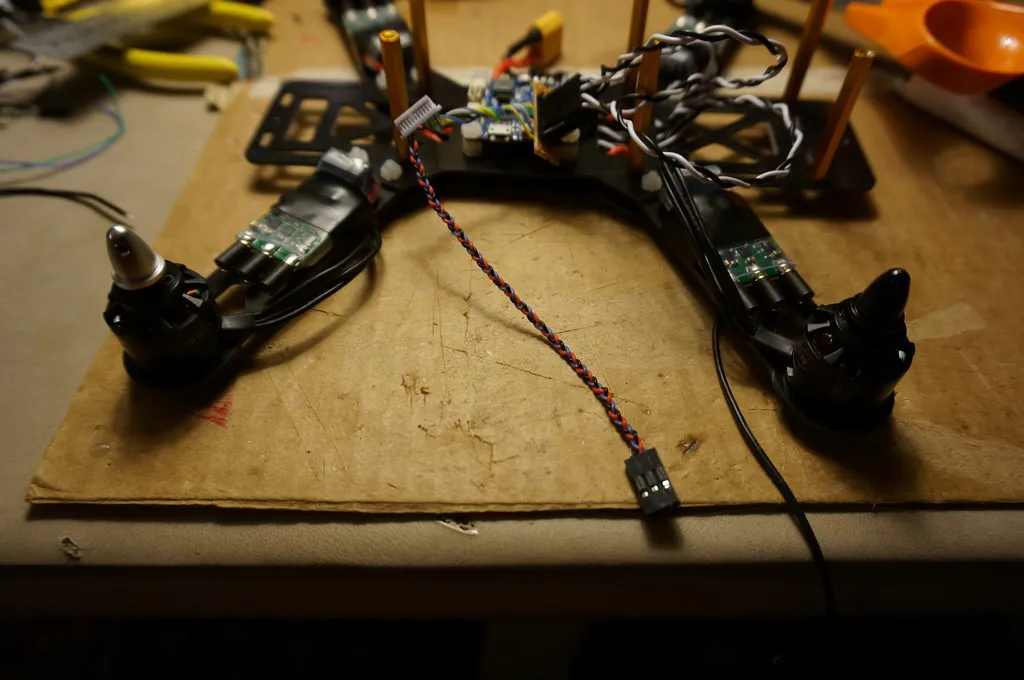
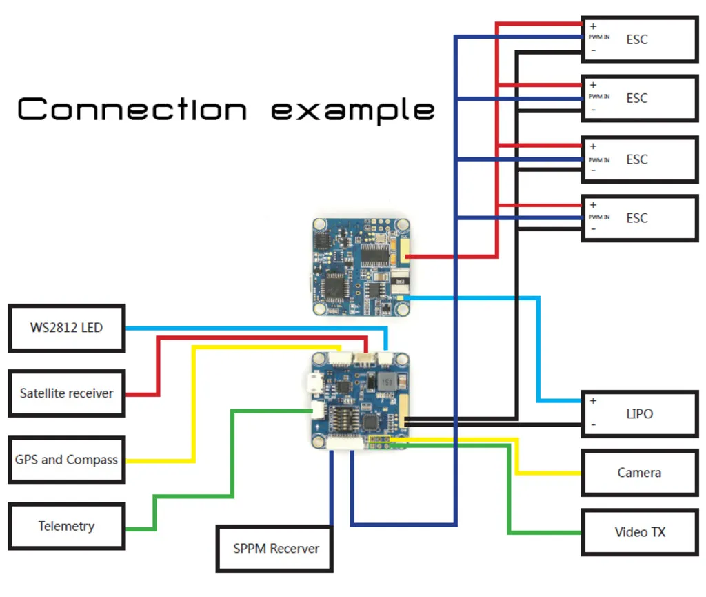
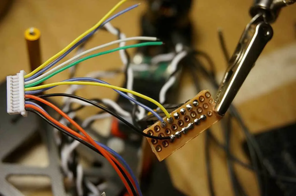
You’ll wire the ESCs like this:
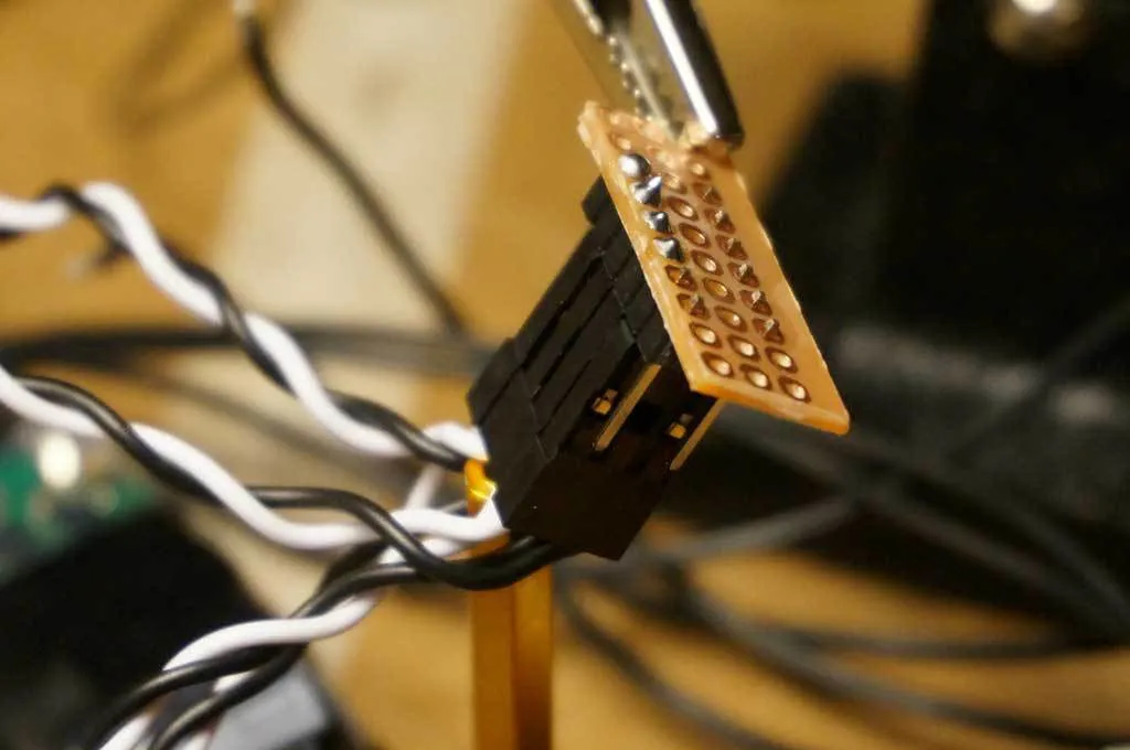
I made a little breakout board for the ESC signal and ground lines. This isn’t necessary if you’re using an ESC without signal cables pre-soldered (like these). If you’re using ESCs without pre-soldered signal cables, the OZE32 cable leads are long enough to solder them straight to the ESC. Awesome!
I used some leftover pins from an Arduino and some prototyping board.
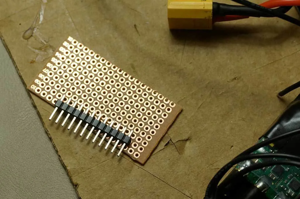
Here’s how I soldered up the headers:
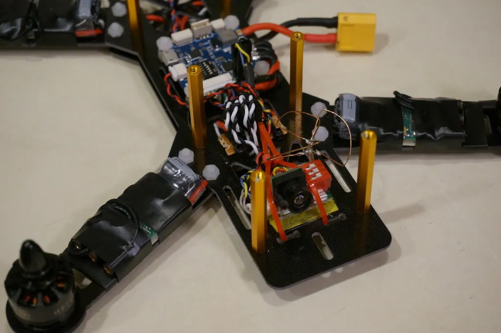
Hardware Setup - Camera and VTX
Since there is no on board 12v power regulator, you should consider getting a 5v camera and video transmitter.
I used this 1 gram CMOS Camera:
and this 400mw Video Transmitter:
The video isn’t quite as good as my CCD Camera, but I have yet to find a CCD camera that will run off 5v. If anyone know of one, please let me know!
Solder on a cloverleaf and a set of dip switches and you’ll end up with something like this:
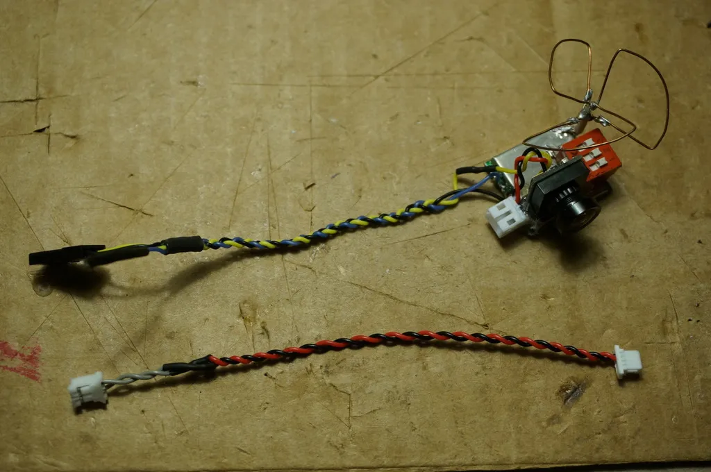
You could solder the power leads straight onto the camera/vtx. I’ve also removed the extra wires from the JST plug.
Remember that the Video Out pin is on the outside of the board. Don’t plug your 5v setup into the middle, 12v pins!
Checkout the OSD overlay and the camera video quality:
Firmware Setup
First, I just got an update from Paul at Ready To Fly Quads that they’re shipping the OZE32 with CleanFlight 1.10.0 and ScarabOSD with all the right flags set. So feel free to fly this stock. For those that want BetaFlight (you should want it, it’s awesome) or like to live on the bleeding edge (myself included), read on and flash away!
Since this board is essentially two different pieces of hardware smashed together onto the same board, we’ll need to update both the flight controller and the MinimOSD independently.
Before you get started flashing, make sure you have the latest CP2102 USB/UART driver installed.
Flash BetaFlight
Let’s flash the FC with BetaFlight first. The same applies if you want to use CleanFlight, just use the appropriate hex file.
Download the Naze32 hex from the BetaFlight Release Page: /downloads/https-github-com-borisbstyle-b.
Unplug the FC if it is plugged in.
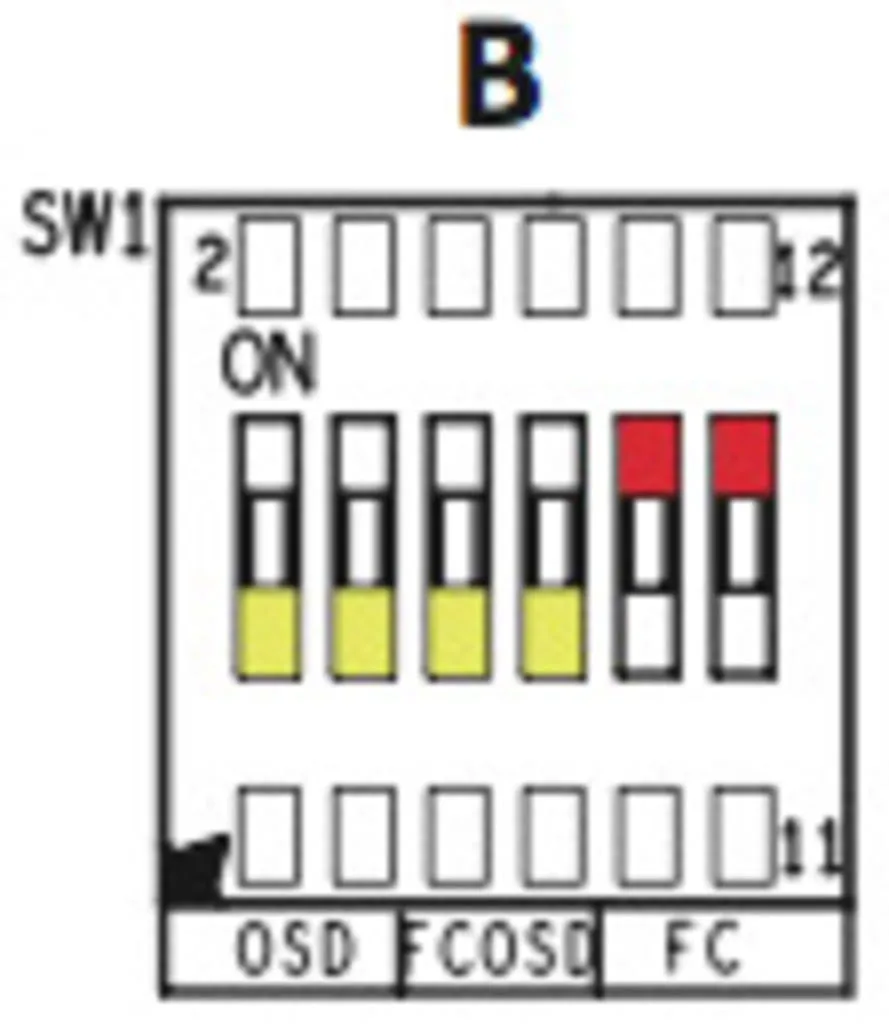
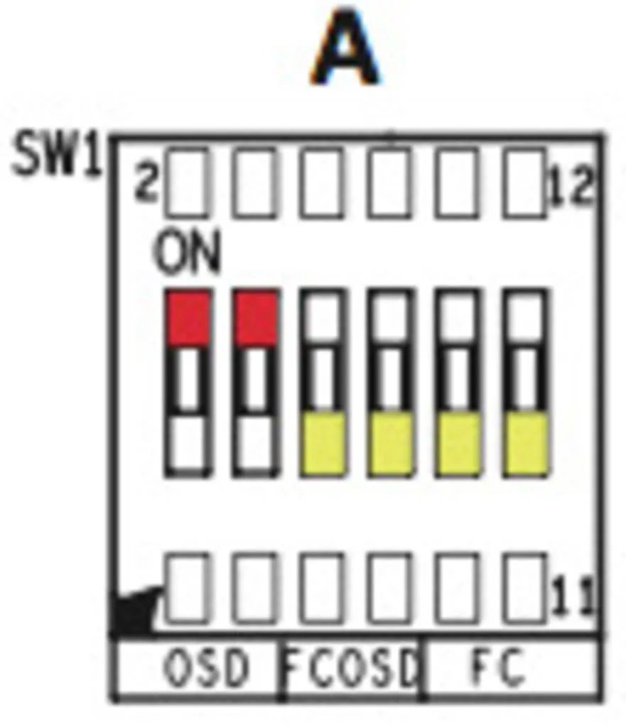
Switch the dip switches into the USB to Flight Controller mode, like so:
Plug in the FC via USB.
Open the CleanFlight configuration tool from Google Chrome and switch to the Firmware Flasher tab.
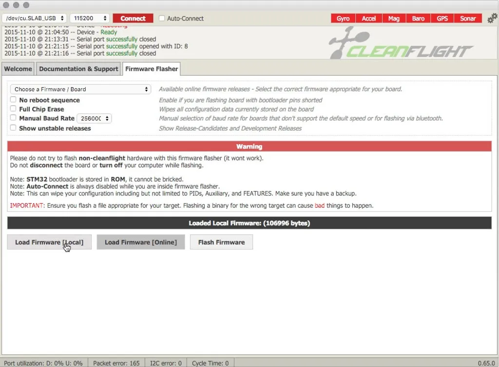
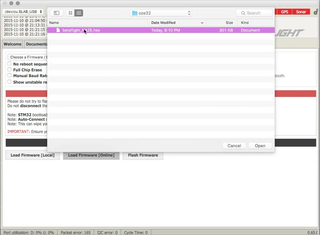
Click Load Local and pick the Naze32 hex file you downloaded.
Click Flash Firmware
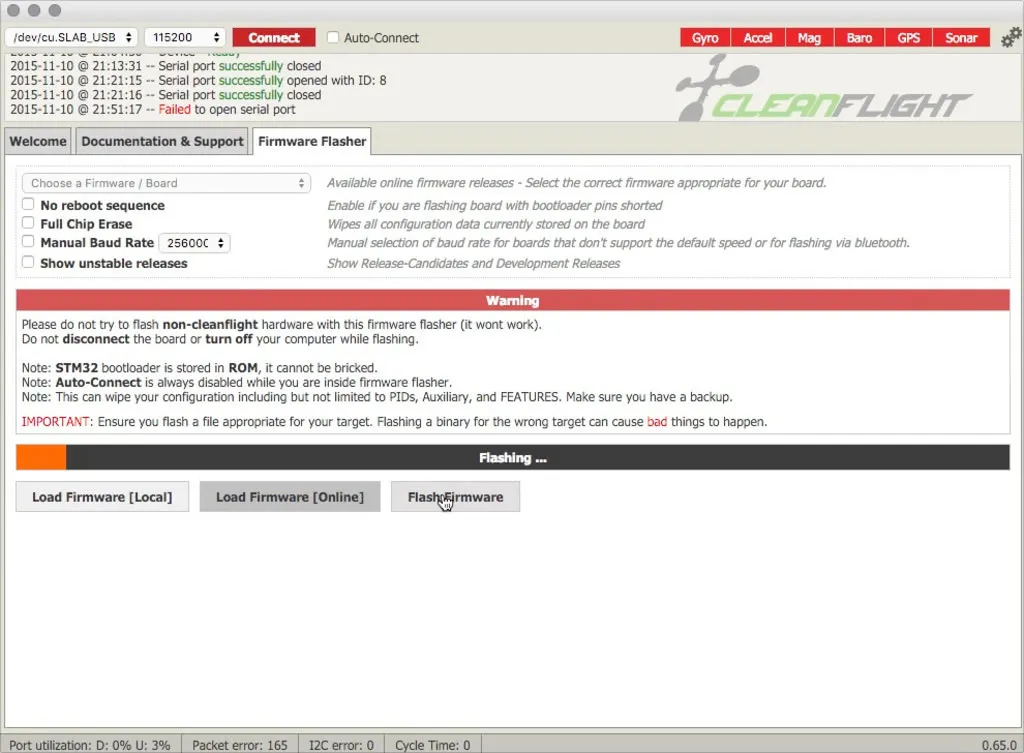
If you get a message that CleanFlight can’t connect to the bootloader, you may need to unplug power from the FC, place a jumper across the tiny boot pads while plugging in the power. It’s kinda tricky to jump those pads, so don’t give up on the first try.
You’ll know it worked if you get a solid blue light. I used a pair of tweezers to jump the pins while I plugged in the USB cable.
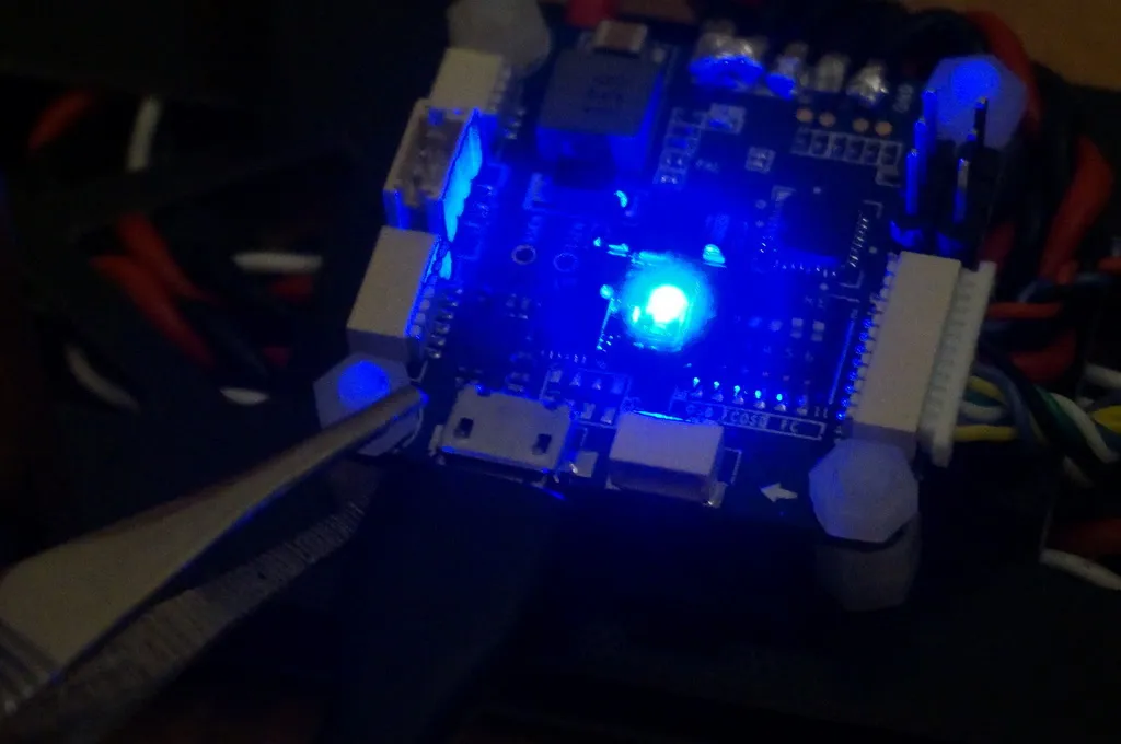
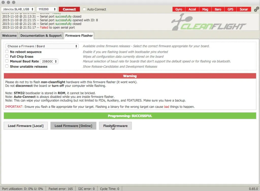
Once you get the solid blue light, hit Flash Firmware again and it should work.
When flashing completes, click Connect, then we’ll configure the current sensor:
-
Switch the receiver configuration to Spektrum satellite or PPM depending on your RX
-
Enable the current sensor feature
-
Hit save
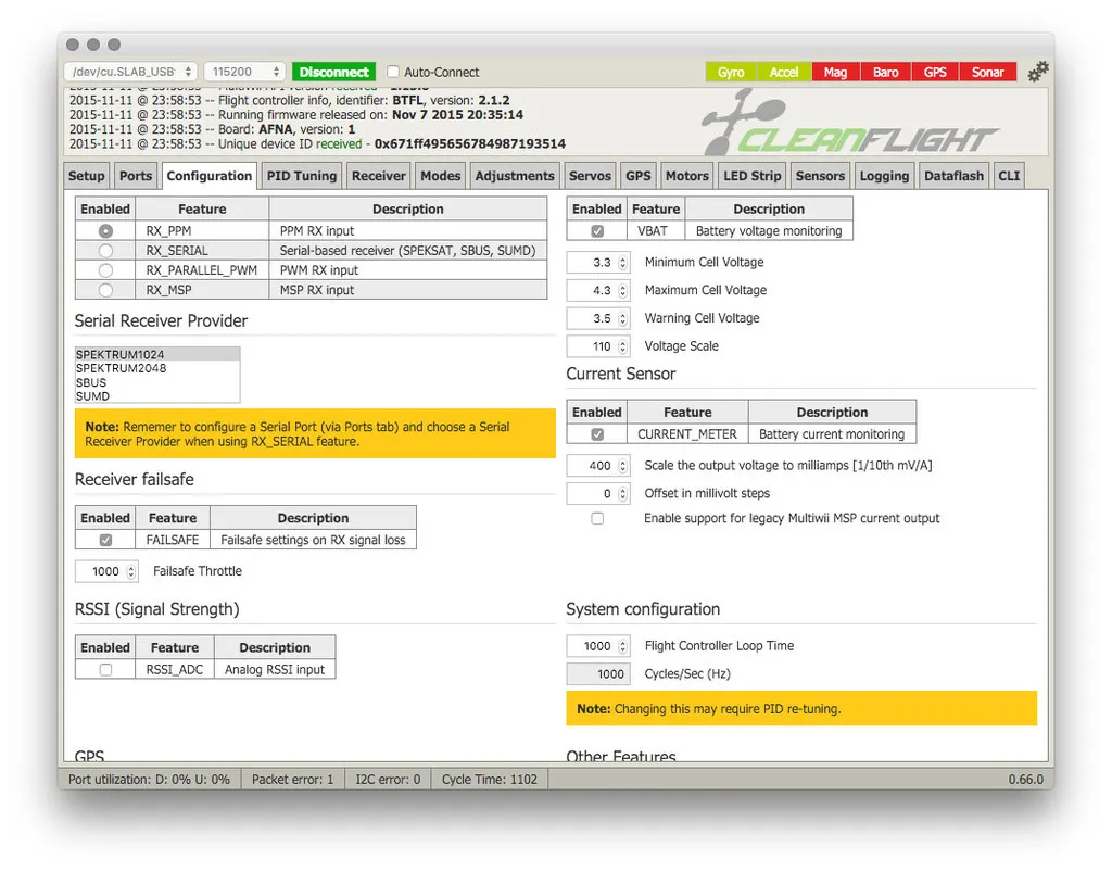
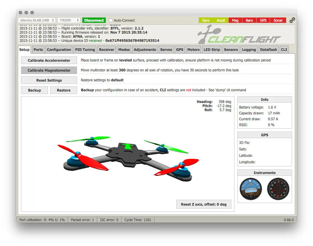
You should now see the total capacity drawn and instantaneous current draw:
Continue your configuration by following the
You can find my BetaFlight 2.3.1 configuration for the BeeRotor160 here: https://gist.github.com/nathantsoi/1fd3bc42977305d1a86d
Flash Scarab OSD
Let’s update the firmware on the MinimOSD with the most actively maintained fork of MinimOSD — Scarab OSD
Hit “Download Source” on the release page for ScarabOSD: https://github.com/ShikOfTheRa/scarab-osd/releases. Extract the zip file.
Open Arduino, download it first, if you don’t already have it. From Arduino, open the MW_OSD folder in the extracted Scarab OSD source and from that folder open MW_OSD.ino.
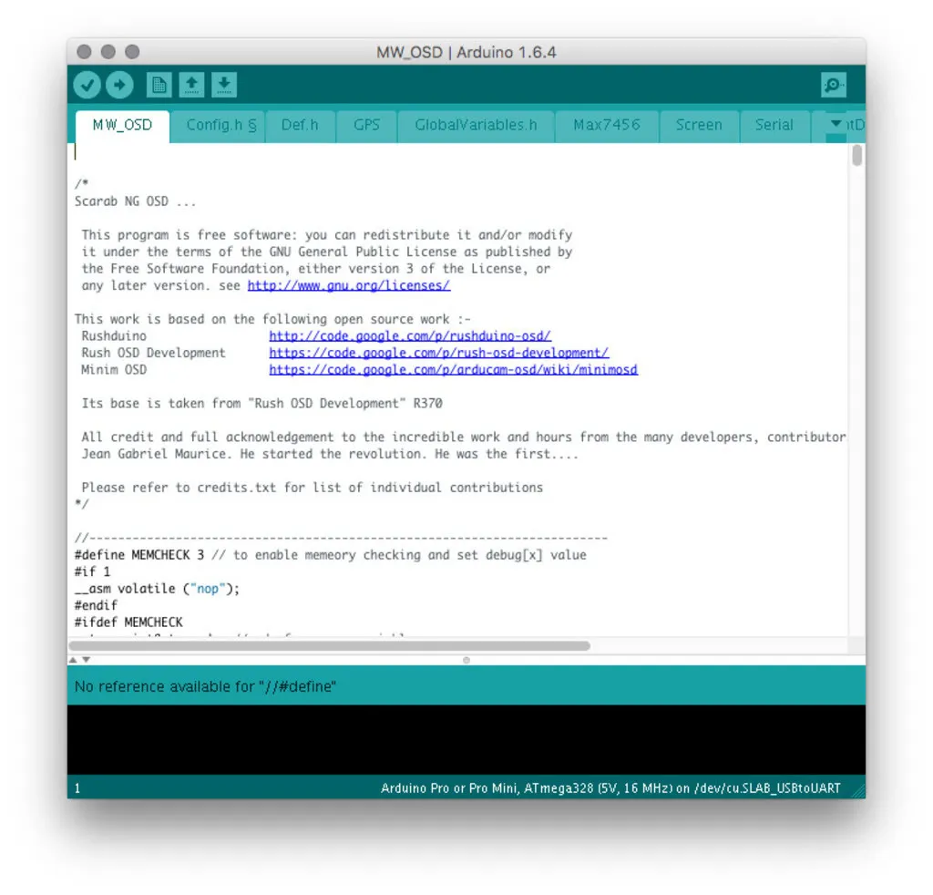
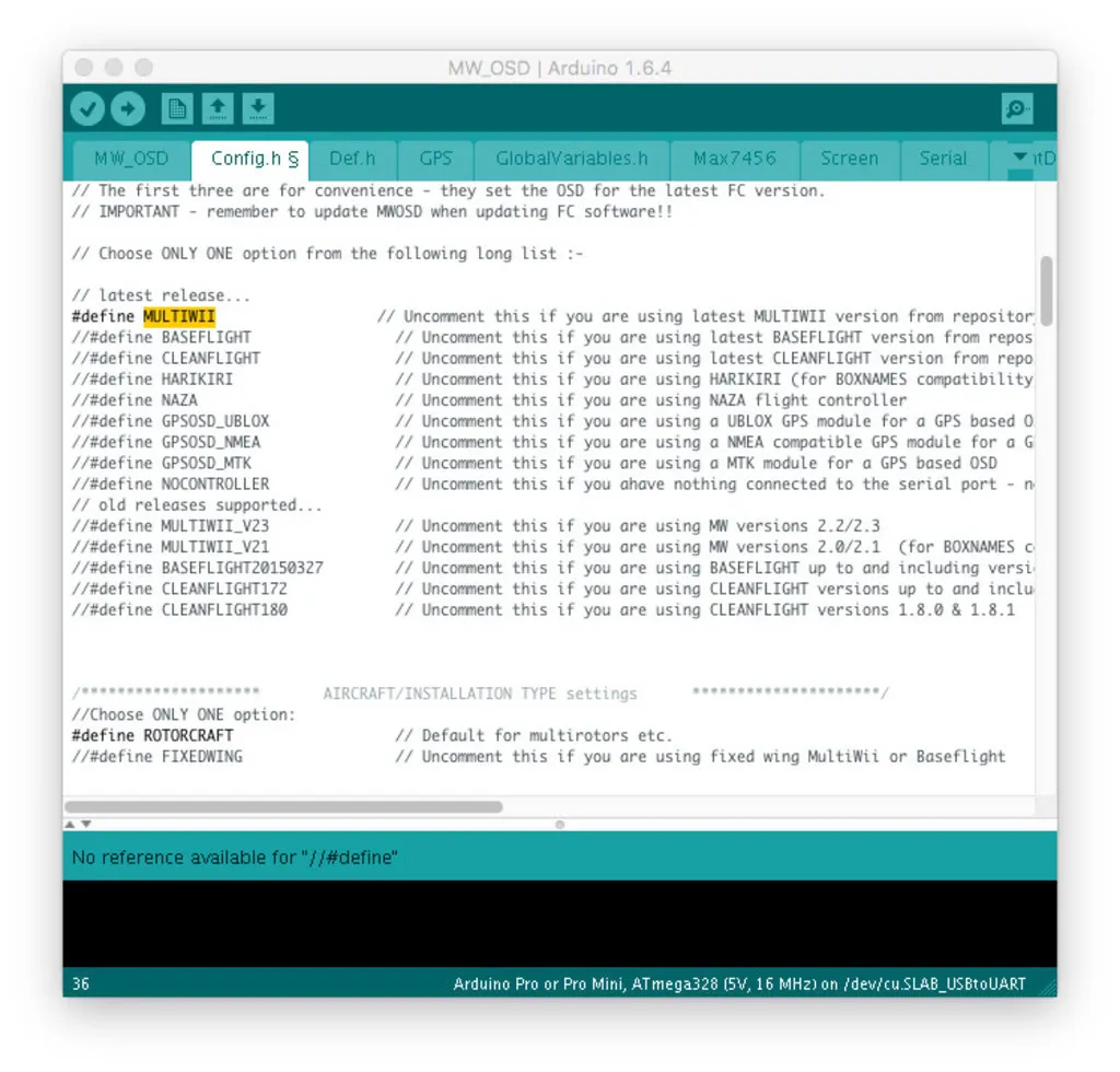
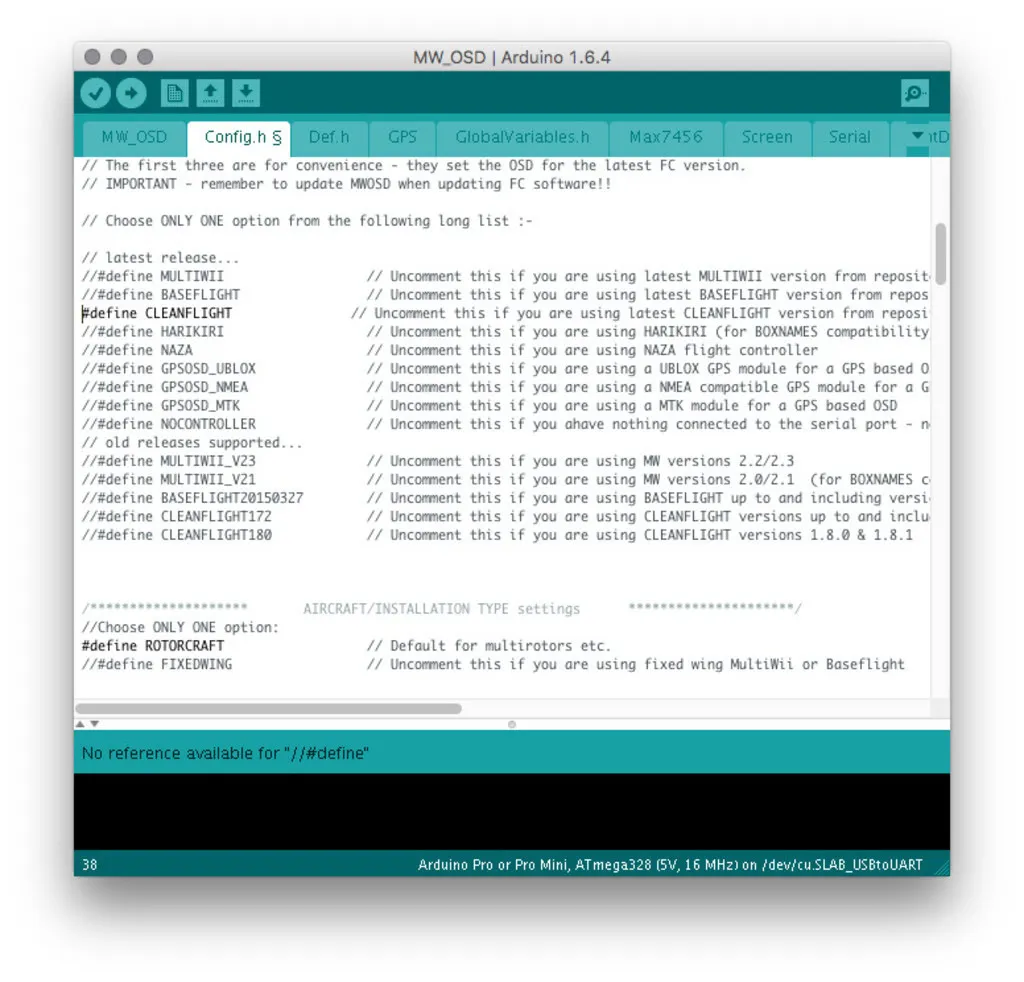
Switch to the Config.h tab and scroll through the file or use the find function to change the following settings.
Lines that start with // are “commented out” or turned off and lines that start with #define (no //) are turned on.
For example, to change the CONTROLLER SOFTWARE from MultiWii to CleanFlight, change this section to #define CLEANFLIGHT
//#define MULTIWII                  // Uncomment this if you are using latest MULTIWII version from repository (2.4 at time of this MWOSD release)
...
#define BETAFLIGHT                // Uncomment this if you are using BETAFLIGHT (same as CLEANFLIGHT t time of this MWOSD release)
It starts like this:
And should be changed to this:
Set the MSP Speed Setting to MSP_SPEED_HIGH to make the artificial horizon update faster:
//#define MSP_SPEED_MED       // Default
...
#define MSP_SPEED_HIGH    // Enable for faster AHI and speed updates. Requires higher baud rates and increases overhead on the FC to process
Set the Voltage Warning Setting to use the vbat configuration from CleanFlight:
#define FC_VOLTAGE_CONFIG // Additionally uncomment this if you want to use the vbat voltage config with BASEFLIGHT and CLEANFLIGHT on the flight controller (include: min cell voltage, max cell voltage and warning cell voltage)Unplug the FC if it is plugged in.
Switch the dip switches into the USB to OSD mode, like so:
Plug in the FC via USB.
If you have an OZE version 1.0 or 1.01, plug in a battery to the OZE32, the MinimOSD is not powered via USB. On version 1.02 and beyond, the MinimOSD is powered over USB, so no need to plug in a battery.
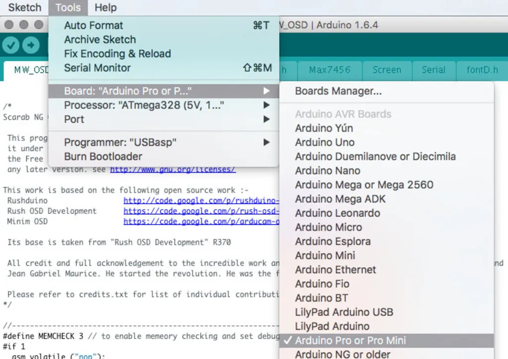
Set the board to Arduino to Arudino Pro Mini
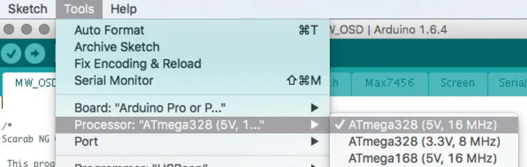
Set the processor to ATmega328 (5v, 16MHz).
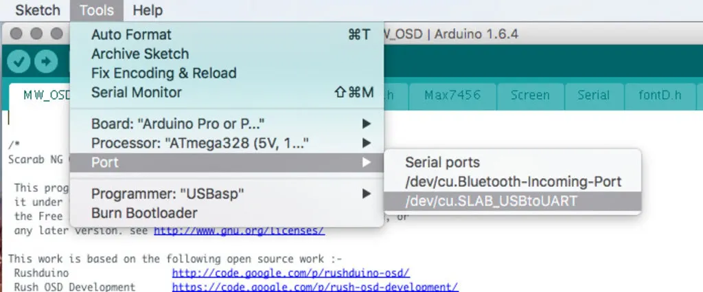
Pick the serial port you’re using:
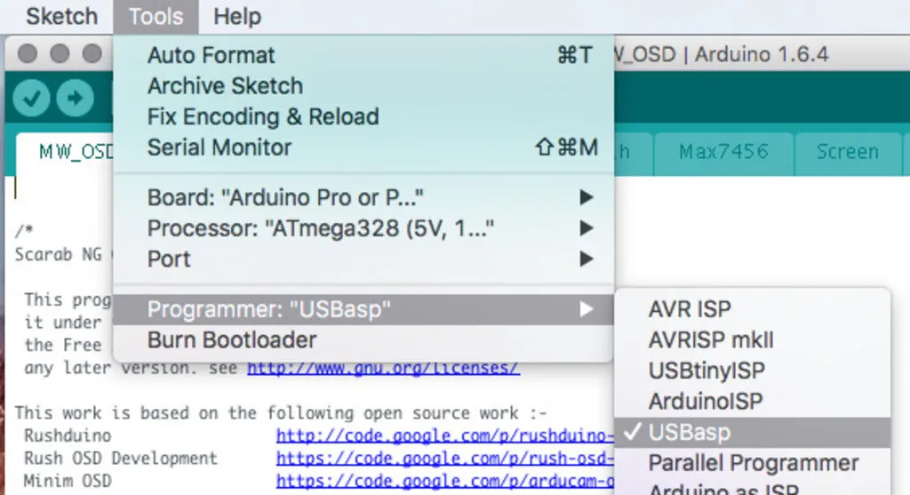
You can ignore the programmer setting unless you’re using an ISP programmer to install a new bootloader. If you are using an ISP programmer (you would have had to soldered leads onto the ISP pads to connect to your ISP programmer), you probably want to set this to "USBasp". This setting will be ignored if you’re flashing via the usb port.
Click the arrow in Arduino to upload the new firmware. The arrow turns orange when the upload starts.
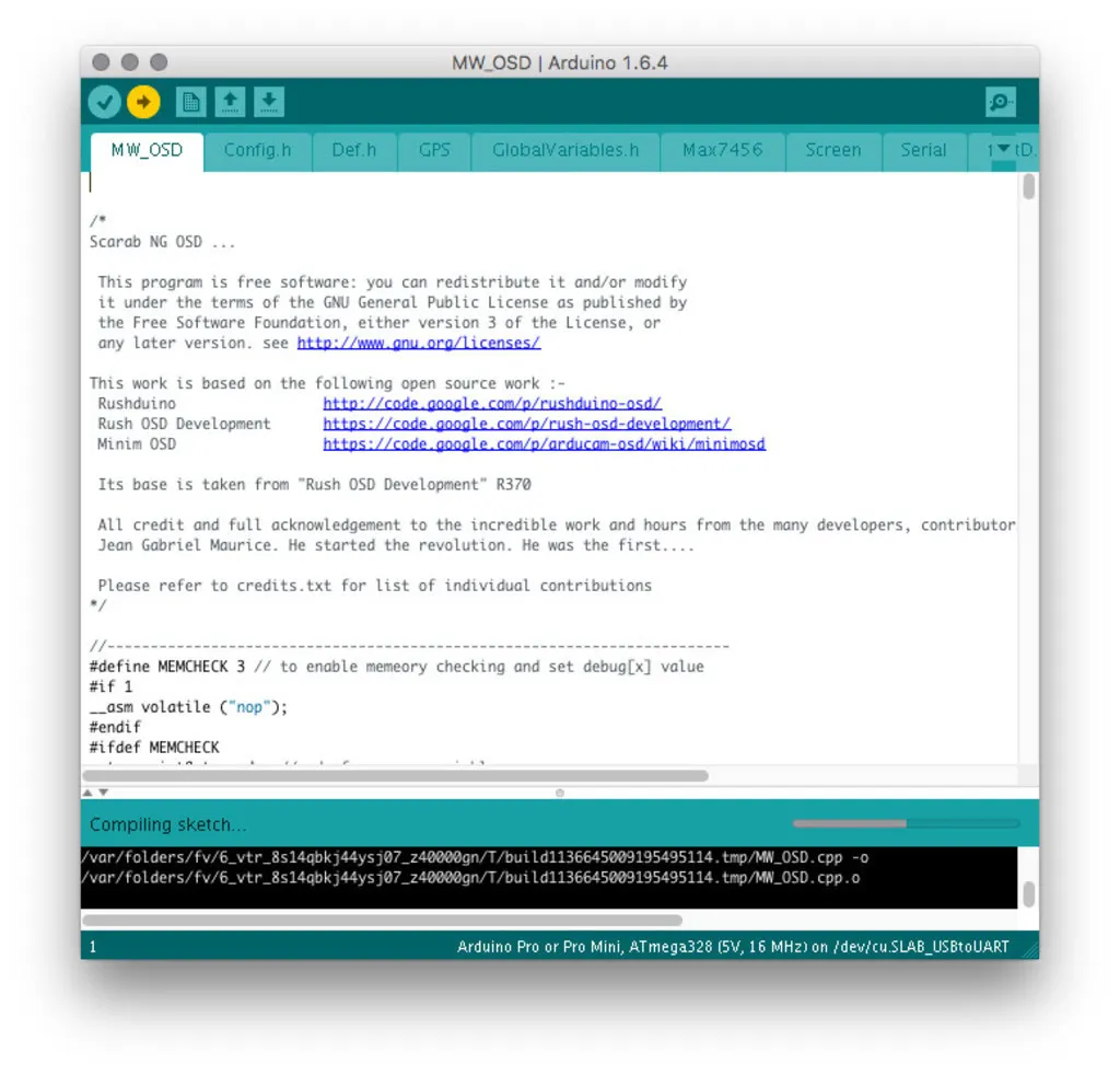
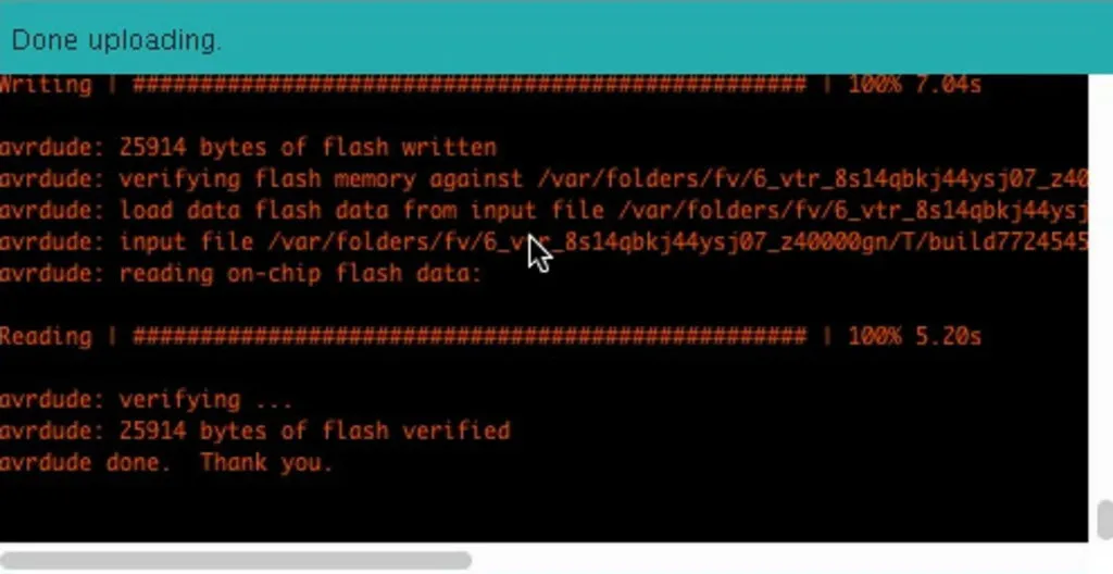
The bottom of the Arduino window will look something like this when it completes:
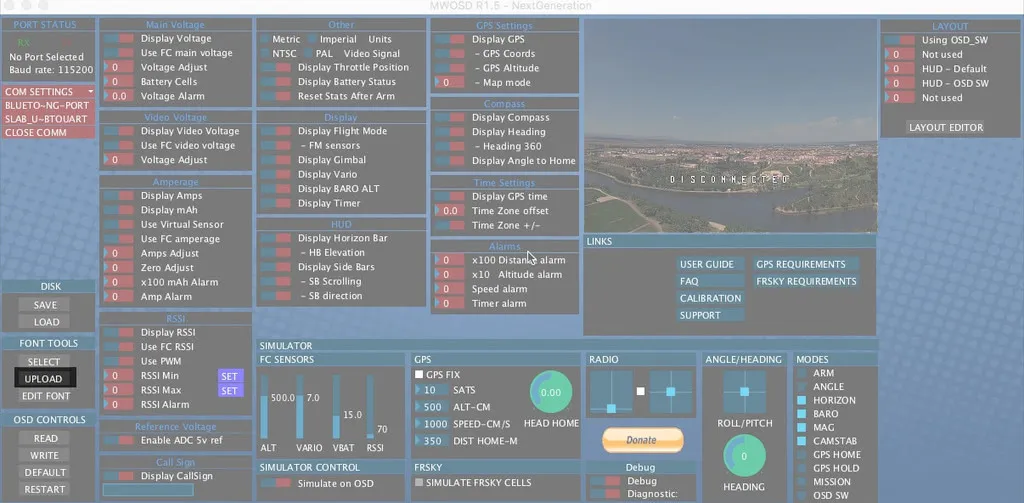
Open up the configuration tool. It is in a folder for your platform in the MW_OSD_GUI folder in the zip file you downloaded.
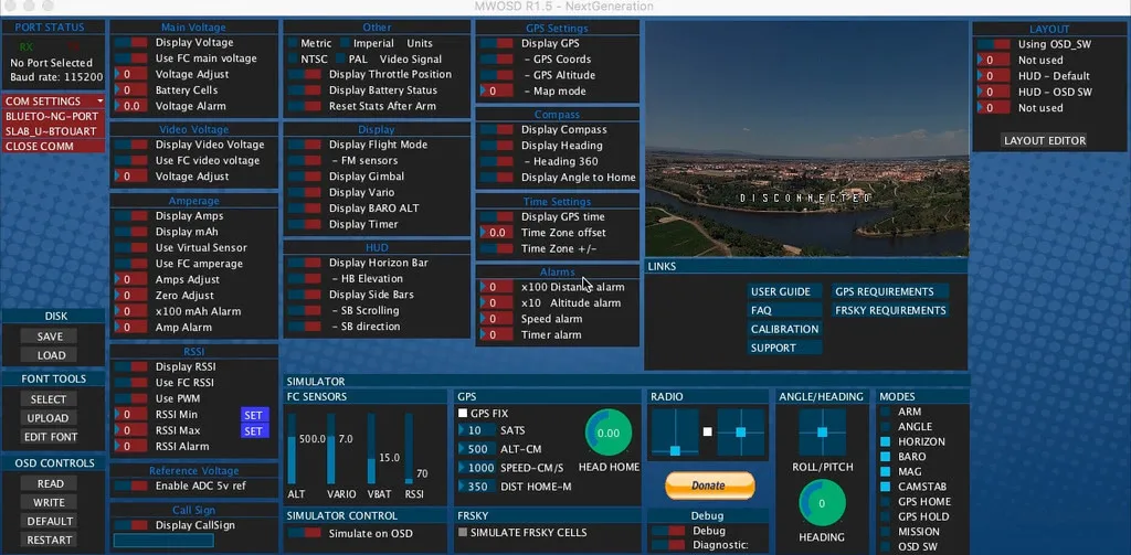
Click the name of your COM port on the left to connect. If you don’t see the COM port, unplug the flight controller, plug it back in and restart the configuration tool.
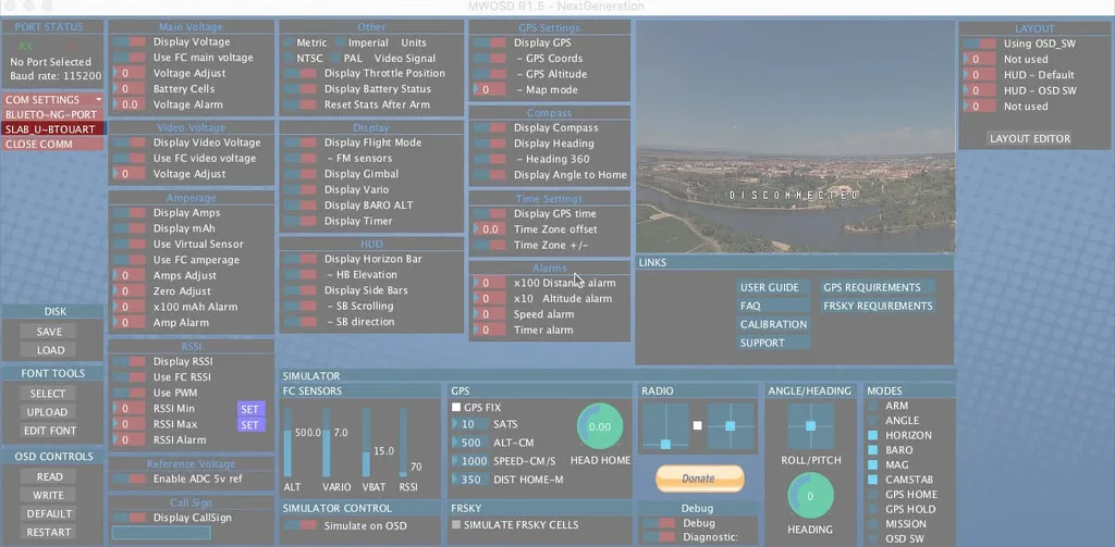
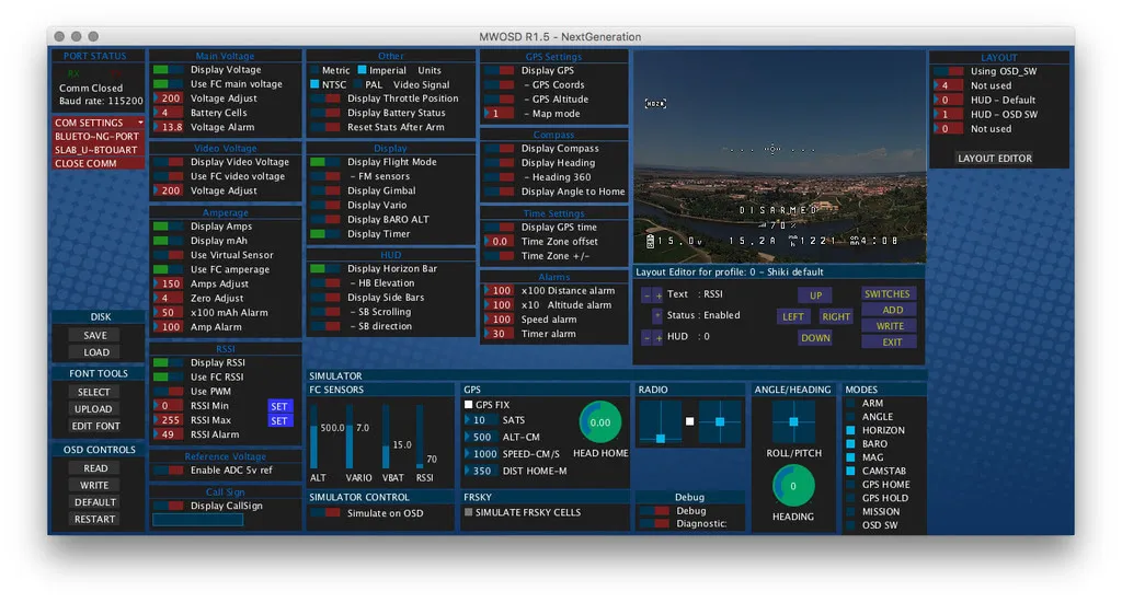
You should see the preview window on the right populate and you can configure your settings. You’ll probably want to turn on Voltage and Amperage settings like so, the number don’t matter, just the switches. This should configure the OSD to display the voltage and amperage from the flight controller.
I also like to update the font. Under the font section select a font, I use the one from the downloaded zip: OTHER/MW_OSD_GUI_SOURCE/MW_OSD_GUI/data/default.mcm. Once you’ve picked a font, hit upload to save the font to the MinimOSD. It will take a minute.
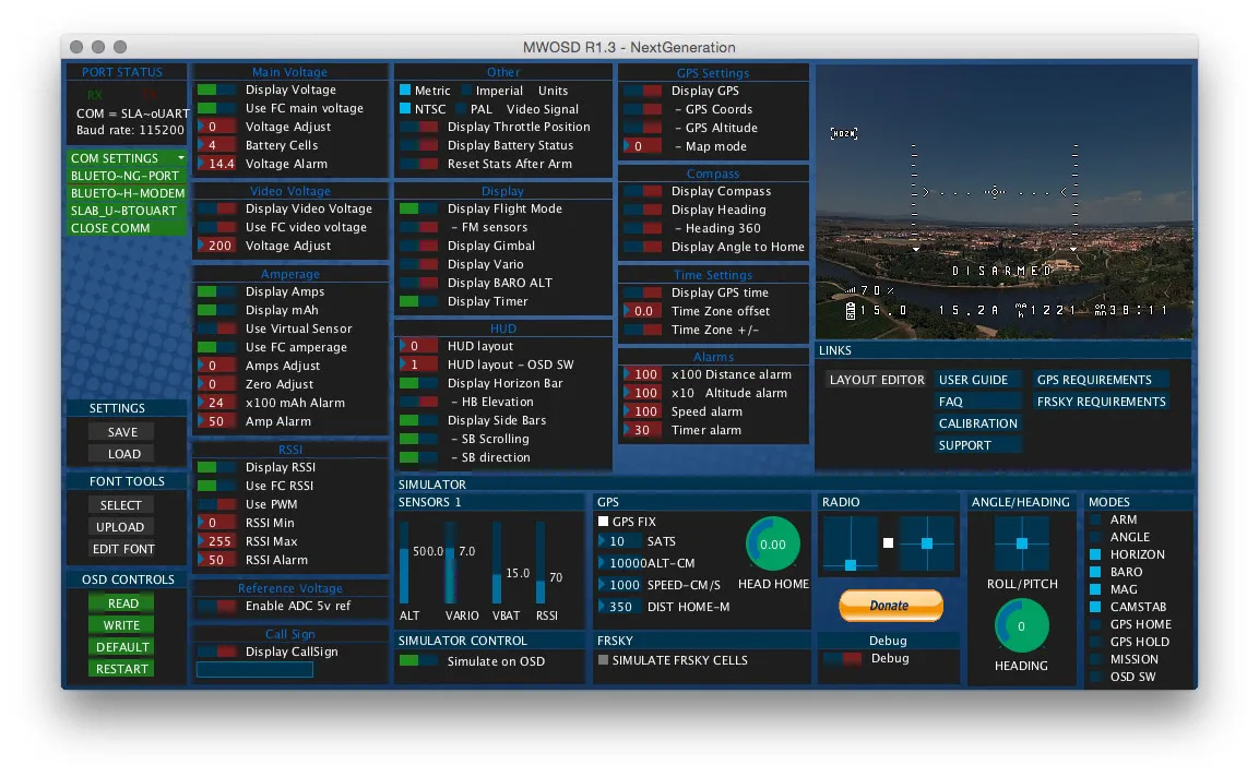
OSD Configuration
Here is my OSD config. Basically we want to take all the values from the flight controller. The adjust values don’t matter, they won’t be used.
Download the config file then click load, pick the file you saved and then click write, or set the settings like this:
When this is all done, you can safely disconnect via the configuration tool and unplug the USB.
Test
Unplug the FC if it is plugged in.
Switch the dip switches into the OSD to Flight Controller mode, like so:
Plug a video transmitter into the video pins on the outer edge of the flight controller. Optionally, plug in a camera to the input side of the video headers as well. We can test without this, so I’ll leave the camera disconnect for now.
Plug in a battery, be careful if you have plugged in the middle “12v” pin on the video header. Be sure your vtx can handle the full battery voltage. I’m using a 2s, so I’m safe. Plus, my vtx can take up to 18 volts or so.
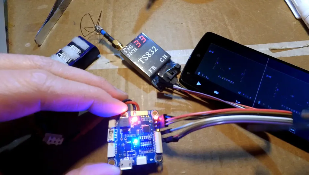
Checkout the awesome text overlay on your video, shown on my phone in the photo.
Time to hook the flight controller up to your receiver and ESCs then go fly!