Omnibus Flight Controller and Airbot Typhoon 180 Miniquad Build
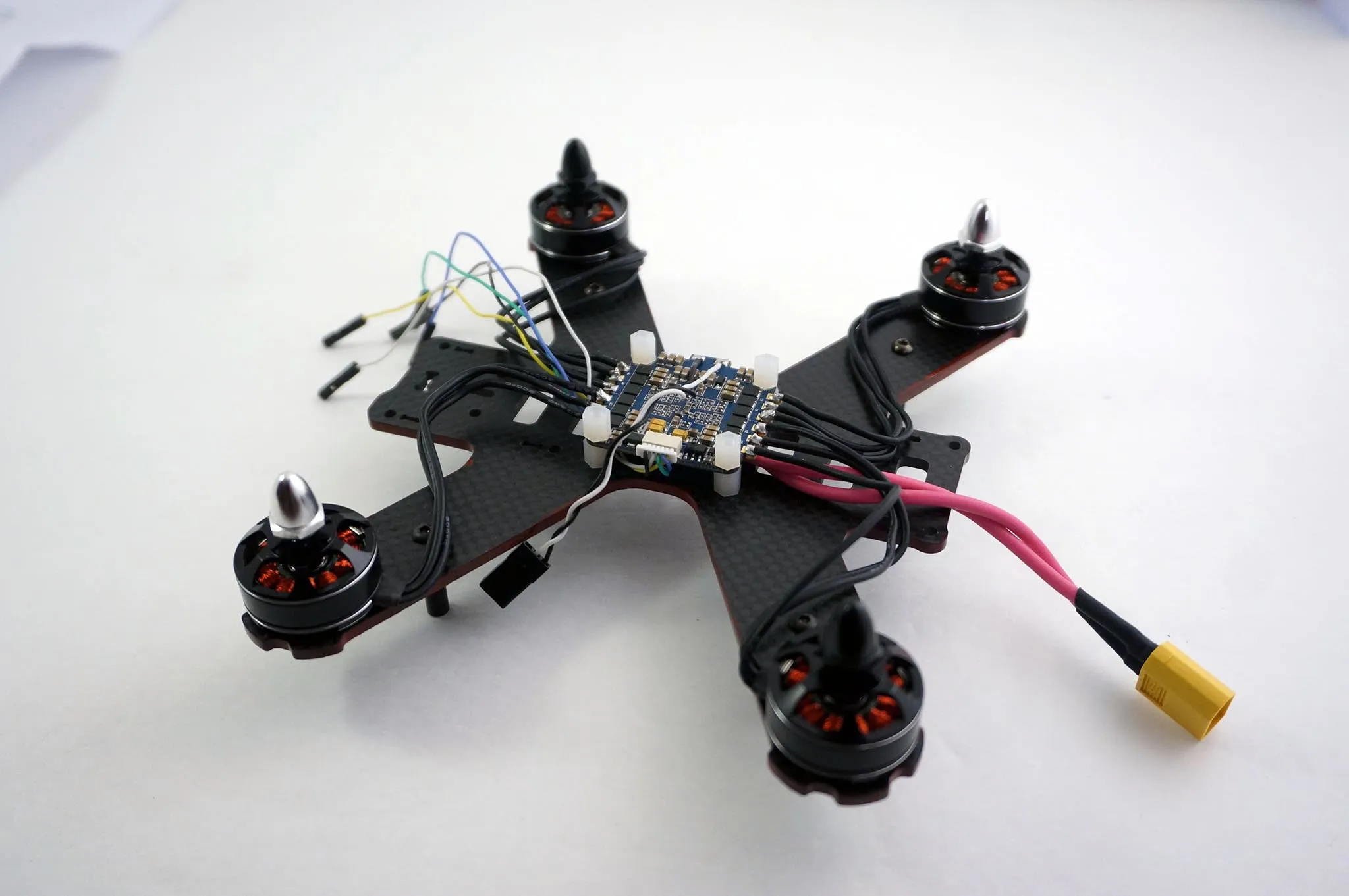
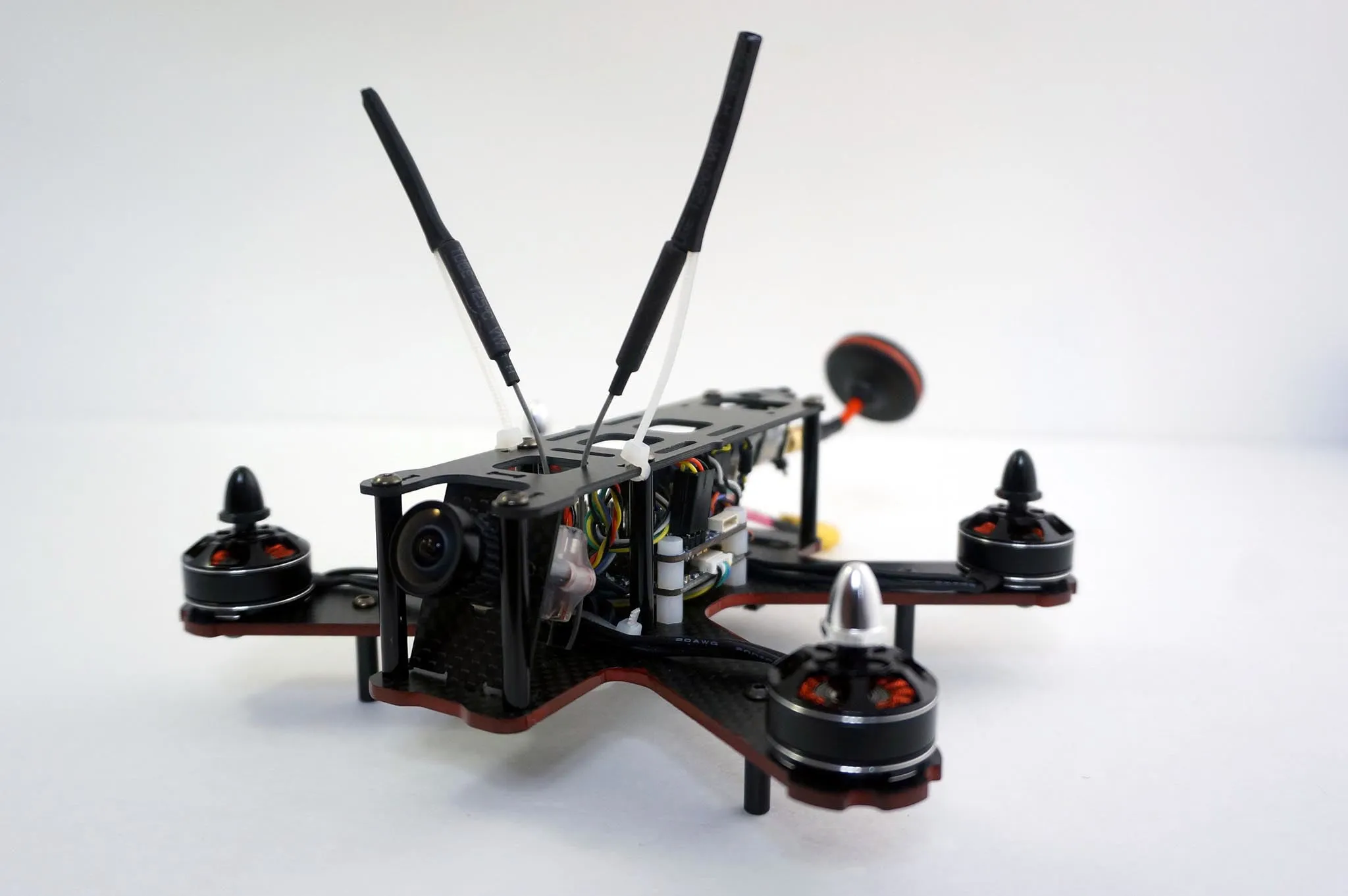
This is a review, build and setup guide for the Airbot Typhoon 180 Miniquad with the brand new OmnibusF3 flight controller.
Review
The OmnibusF3 flight controller uses the MPU6000 over SPI for the best possible flight performance. If you haven’t already seen it, you should checkout Josh’s awesome video on different IMUs. Along with the MPU6000 are a barometer and an AB7456 OSD chip (an upgraded MAX7456) for the BetaFlight integrated OSD.
The OmnibusF3 has an SDCard for blackbox logging and uses the much faster VCP USB link, so it takes minutes instead of hours to copy your blackbox logs off the flight controller.
Finally, you won’t need a PDB with this build because there is a high performance 5v, 1.5a STMicrocontroller L78 voltage regulator (rated up to 4s), so you can plug the flight battery right into the flight controller.
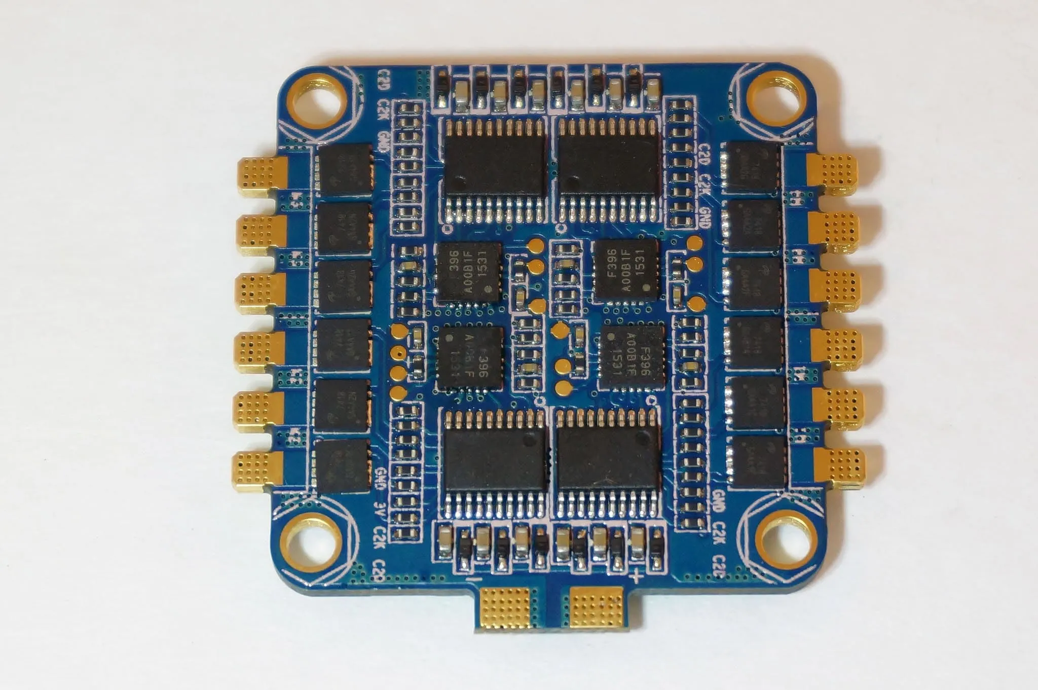
I’ll be using the AirBot Typhoon 4-in-1 Pro ESC.
I have a prototype board. Production boards are gold plated.
Update Aug, 2016: Given how fast BetaFlight development moves, the linked config file is probably out of date. I’ll try to keep it updated, but it’s better to start with the default BetaFlight settings from the latest release and setup whatever features you need, as described below.
Here is my complete BetaFlight 3.0 config, if you want to copy and paste. Please read through the guide to better understand the settings https://gist.github.com/nathantsoi/ee8adb244e62fb4f128e840c785828a4
Pinouts
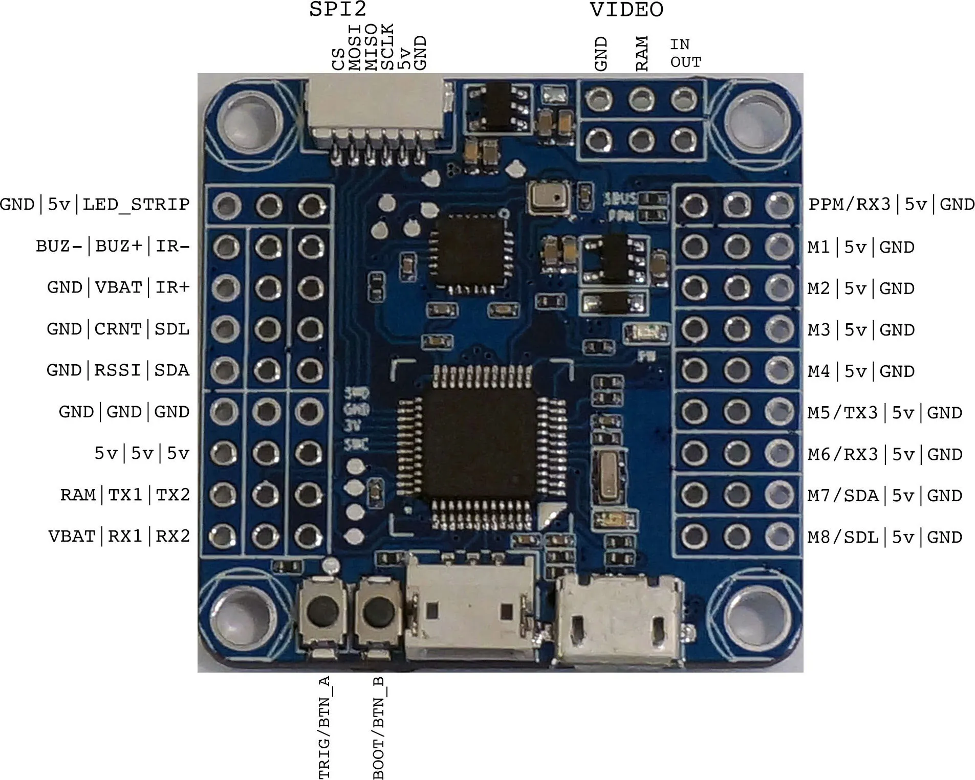
Here is the Typhoon pinout:
Flight controller setup
Update Oct, 2016: Please update your firmware when you get your new board! Even though all boards ship with Firmware 3.0.0 and up, you’ll want to make sure you flash your board to the latest version of BetaFlight because some boards, even if they say firmware version 3.0.0 may have early, release candidate firmware instead of the final version. Update your board before doing anything else! It’s easy, just follow the Firmware Update Guide here.
Let’s start by soldering the pin headers to the board. To choose which headers you’ll use, let’s consider a few things. First, the voltage of the camera and video transmitter you’ll be using. I will be using a camera that can take between 5v-22v and a video transmitter that can take between 7-24v (2s-5s LiPo). This is important because it determines how our video power pins will be wired. If you’re using a 5v camera, you would want to wire any 5v output from the flight controller to the V+ on the camera. If you’re using a camera that can handle the voltage straight from the battery, you can connect VBAT and RAM to power both the transmitter and the camera from the battery. If you’re using FPV gear that can only handle 5v, connect RAM and a 5v line.
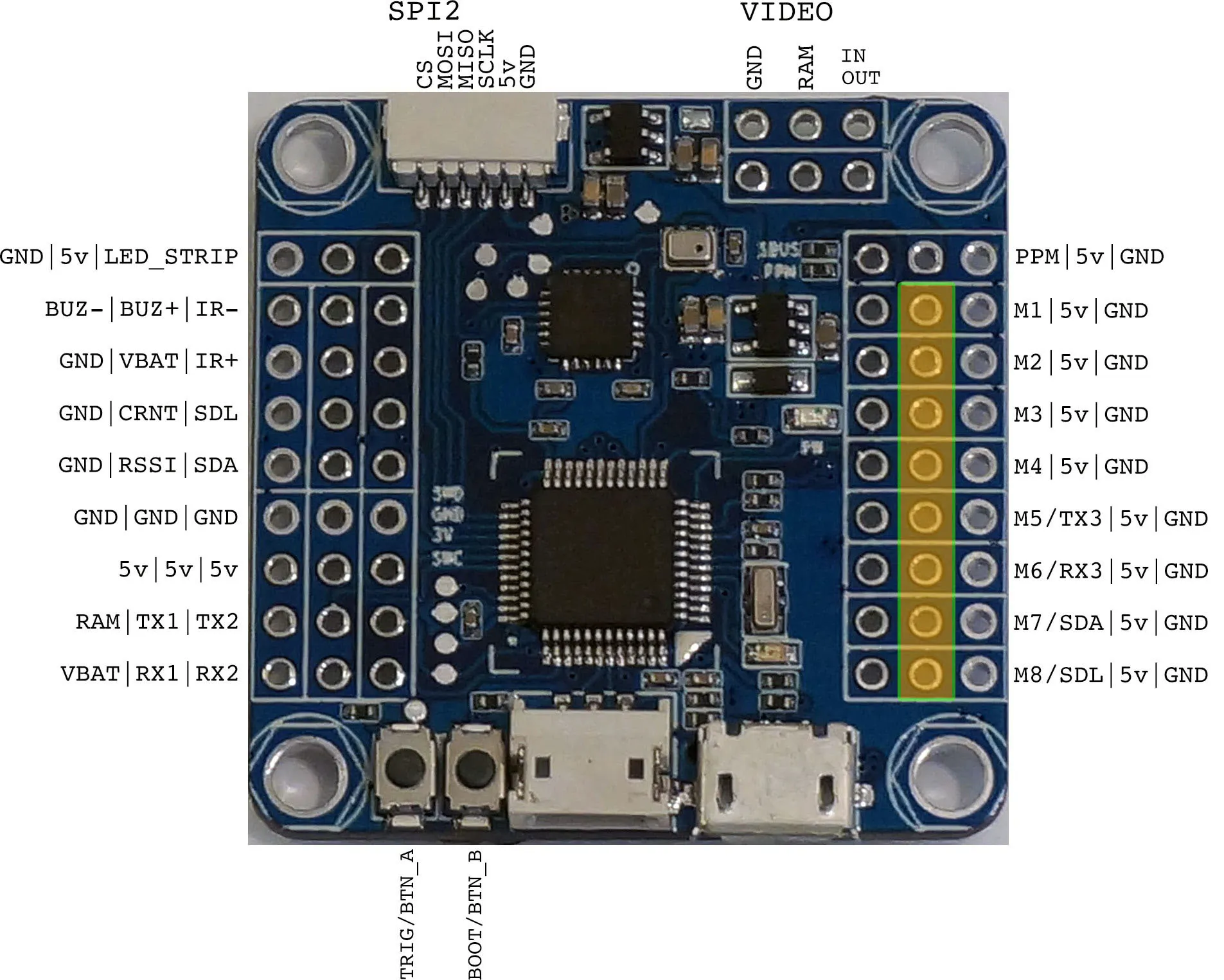
These are the pins I’ll populate:
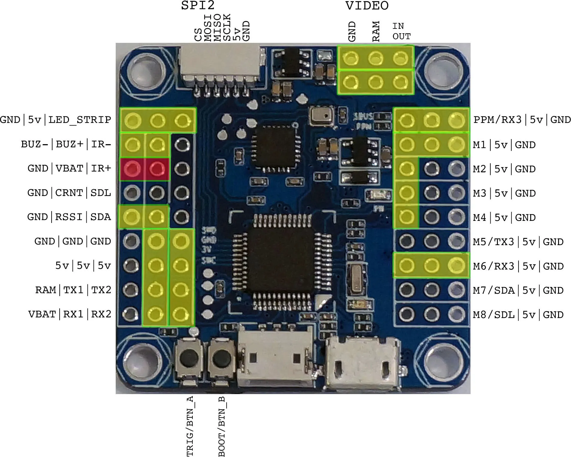
I’ve labeled the battery pins red, since VBAT will have the battery directly connected, be sure not to connect the battery to any other pins!
Note that until you connect one of the RAM pins to a power source, the 3x RAM pins are only connected to each other and have no power.
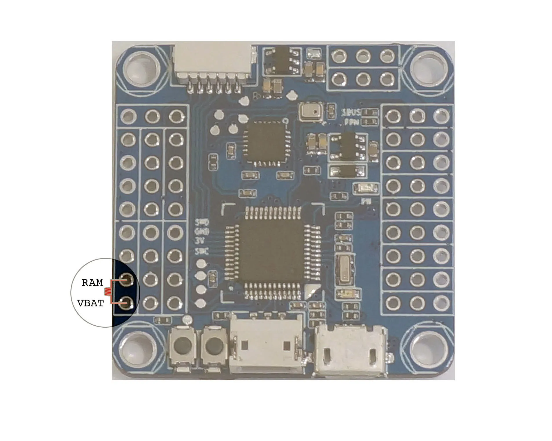
Instead of just connecting RAM to VBAT with a jumper, which will work fine, I’m going to do one better. I’ll use an inductor to connect VBAT and any 5v. If you don’t have an inductor laying around, no worries, just use a wire and connect the two pins.
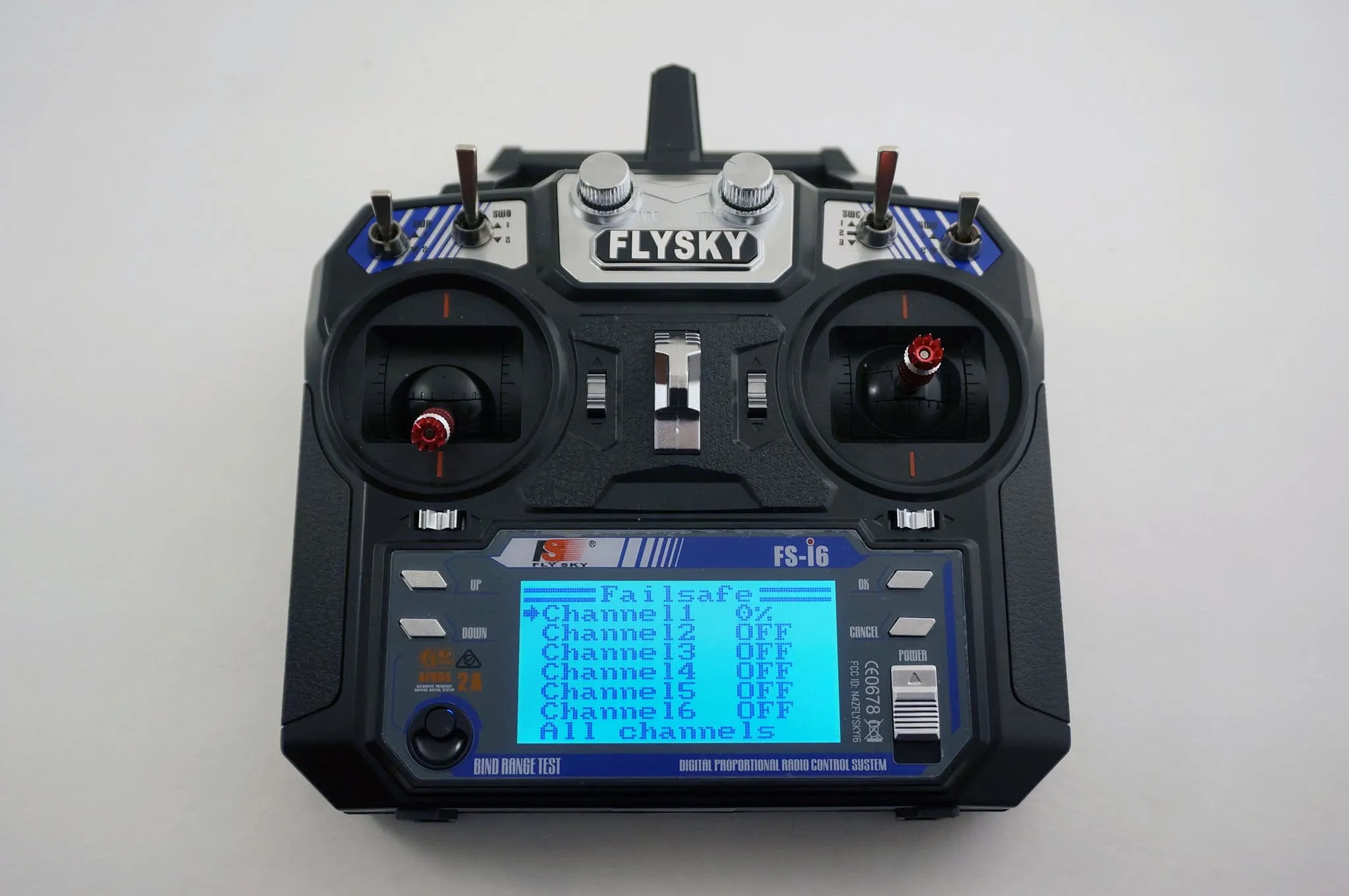
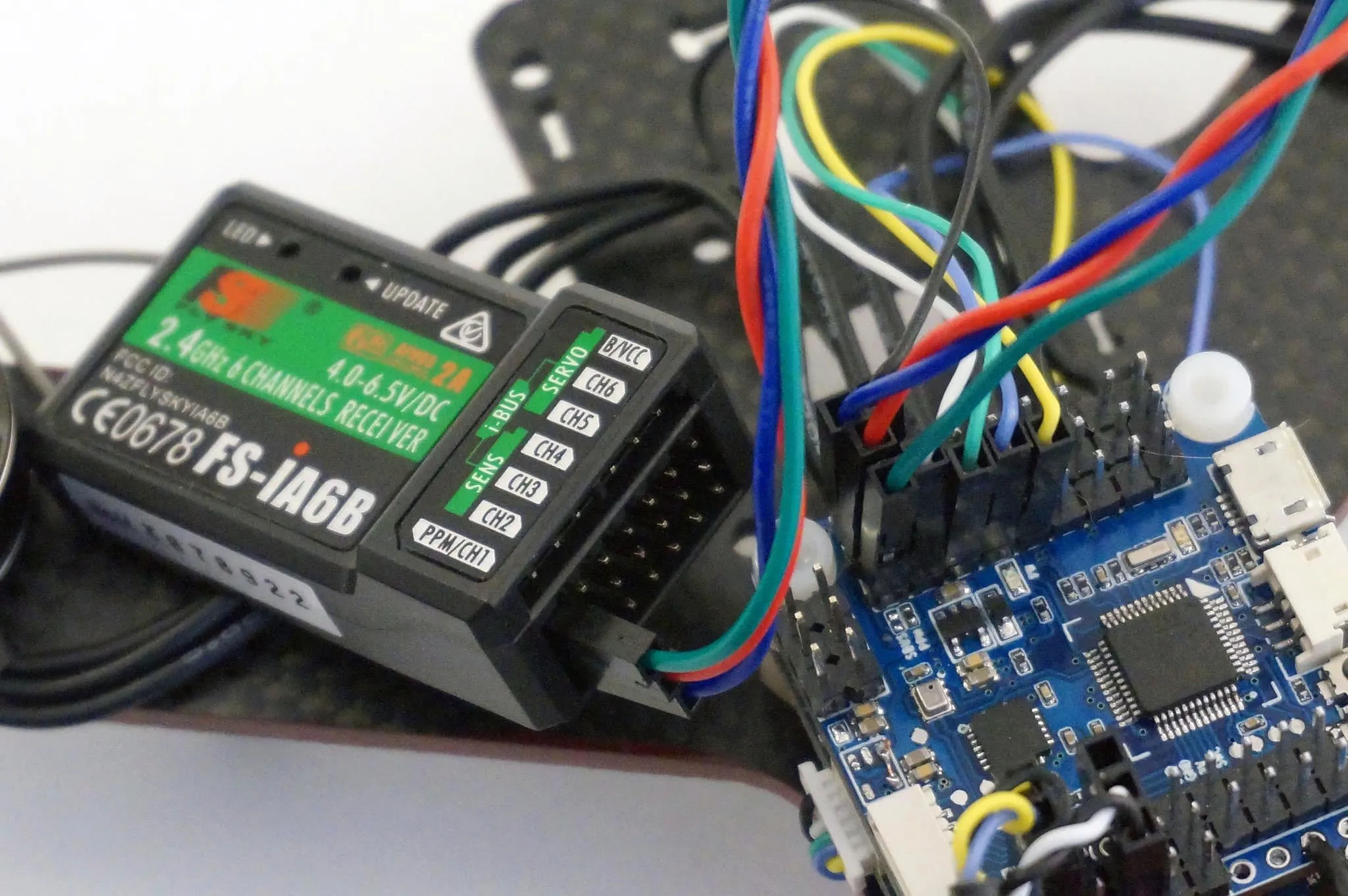
The next thing to consider is what receiver you’ll be using: Serial RX (such as IBUS, FRSKY or Spektrum Satellite) or PPM. I’ll be using the IBUS receiver included with the FlySky FS-i6.
Update Aug, 2016: The PPM pin and SERIAL RX pin are shared between UART3 and PPM. Simply plug in the reciever to the one port and pick PPM or Serial RX in the BetaFlight configurator. This also means that when PPM is in use, UART3 cannot be used. However, if you are out of serial ports, using PPM and need one more, you can remove the SBUS resistor as described below and uncomment this line from the BetaFlight source code #define AVOID_UART3_FOR_PWM_PPM. This will enable both PPM and UART3.
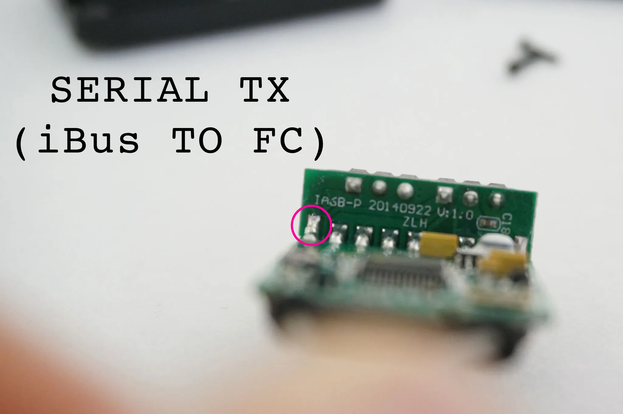
Outdated: My prototype board came with both the PPM and SerialRX resistors connected. At some point there will be software to support using PPM and SerialRX on the same pin allowing you to select between them in the configurator. Until then, you’ll want to remove the resistor labeled SBUS.
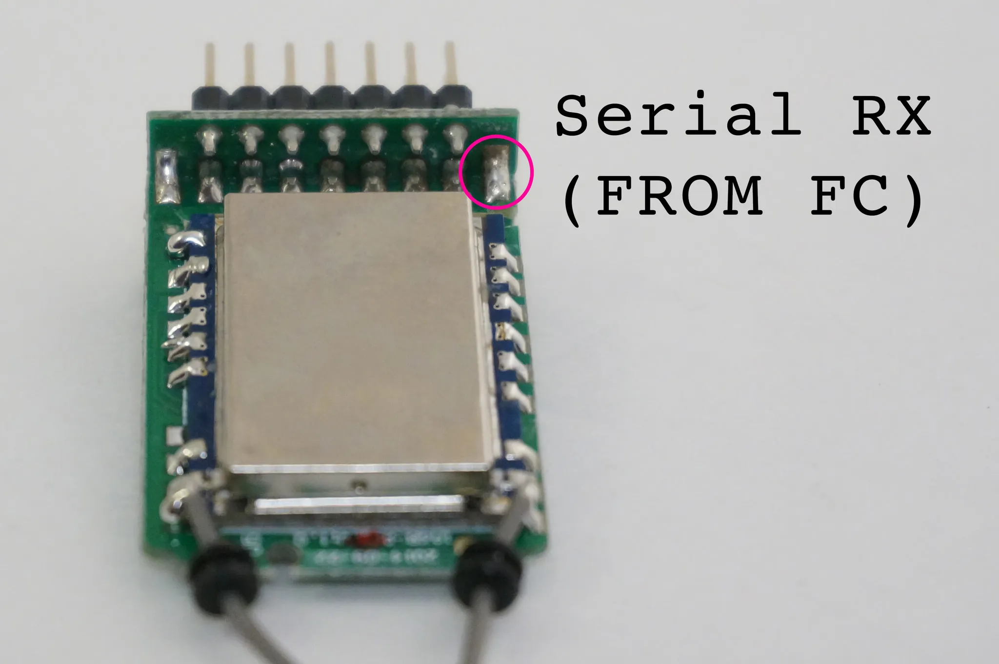
If the SBUS resistor is removed and the PPM resistor is installed, you’ll want to connect your SBUS or IBUS or any serial receiver to a different serial port:
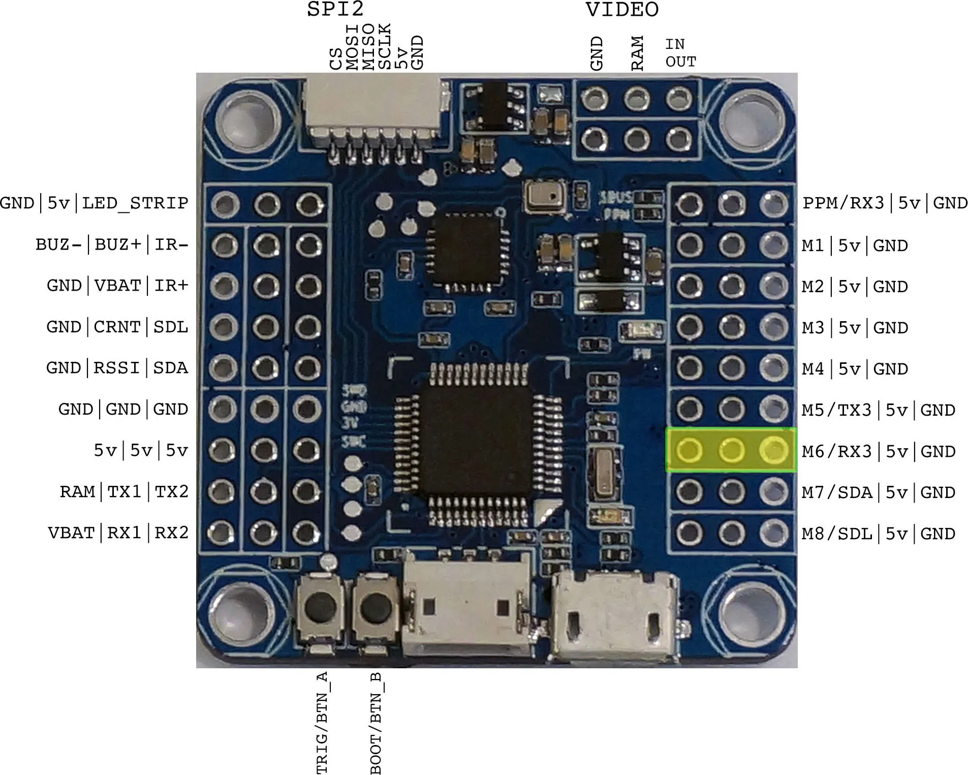
Note that this 5v rail does not get power from the flight controller, but is isolated, in case you’re using ESCs with a 5v BEC.
This means that it might be easier to plug your serial receiver into UART1 or UART2 (this is how I configured my quad).
Parts
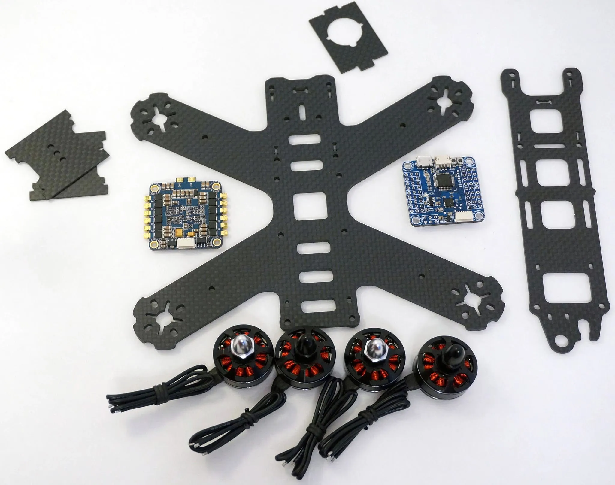
Here are the parts we’ll be using for this awesome little 180mm quad.
| Image | Description |
|---|---|
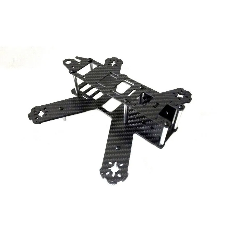 | Frame: Lisam LS-180 180mm Carbon Fiber Frame Kit Mini Quadcopter |
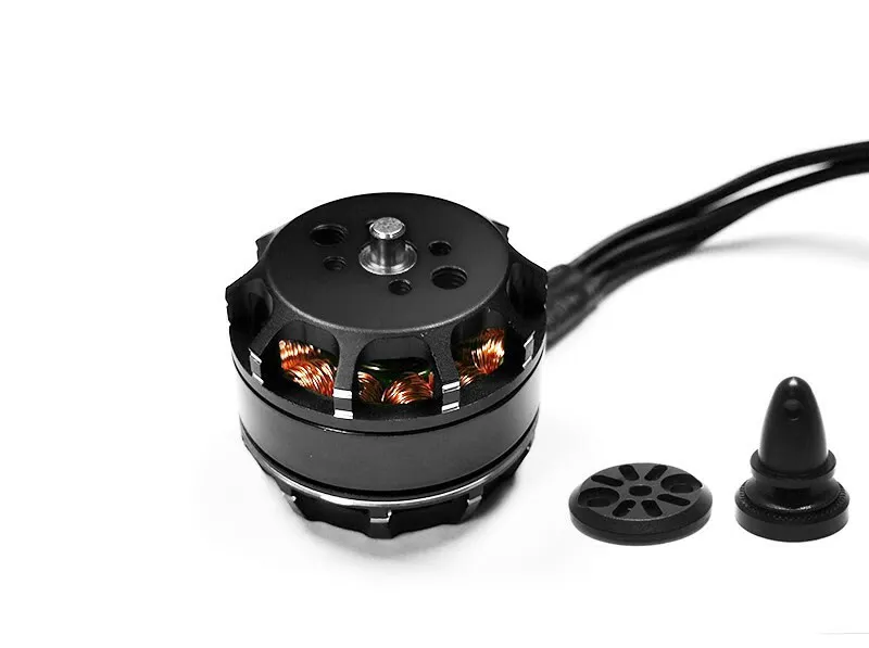 | Motors: Micro Titan 2204 Motor 2300KV v2 |
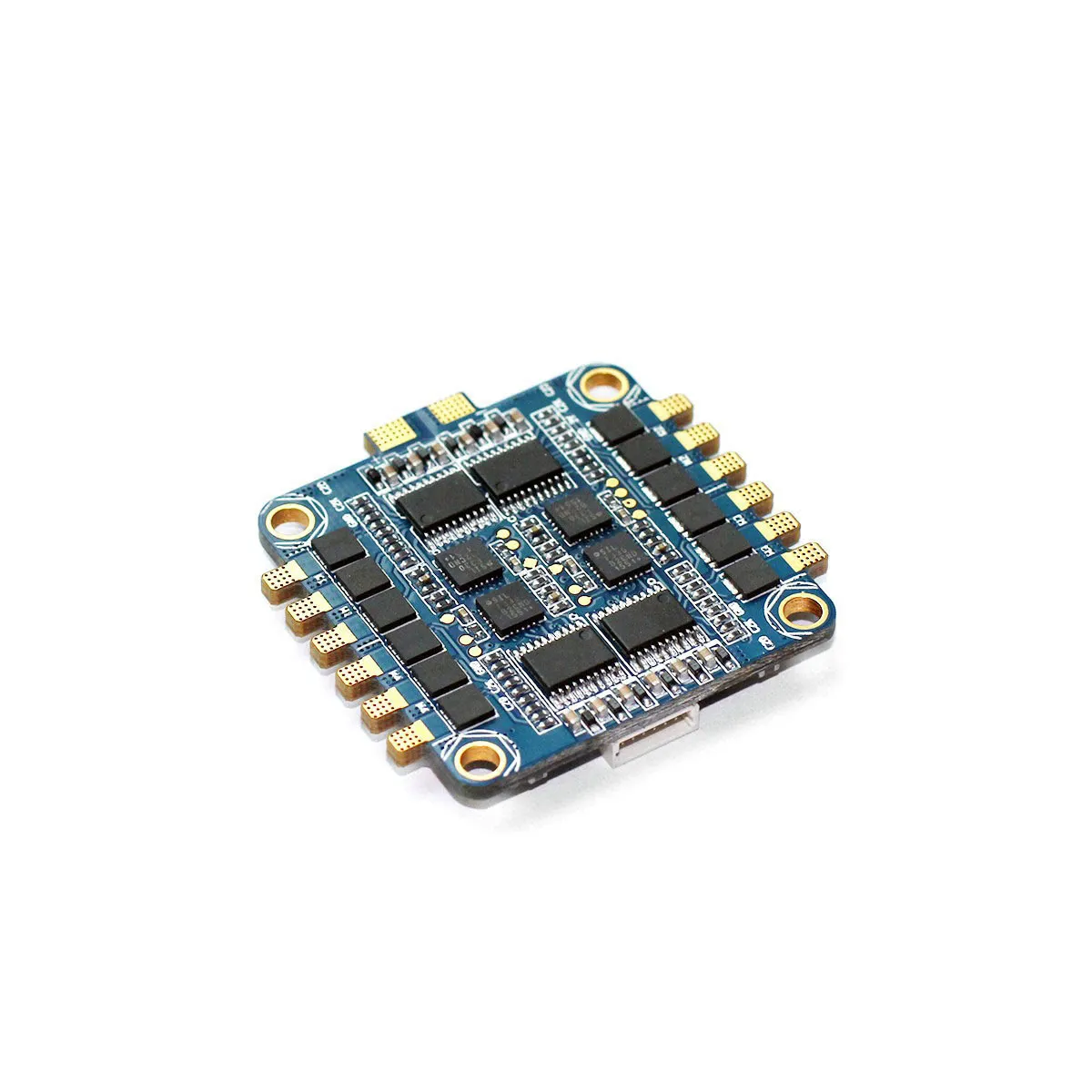 | ESC: Typhoon 4x20A 4in1 ESC PRO |
| Flight Controller: OMNIBUSF3 with an integrated BetaFlight OSD |
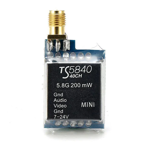 | Video Transmitter: Eachine TS5840 Upgraded 40CH 5.8G 200mW |
 | Video Antenna: 5.8ghz Circular Polarized Antenna |
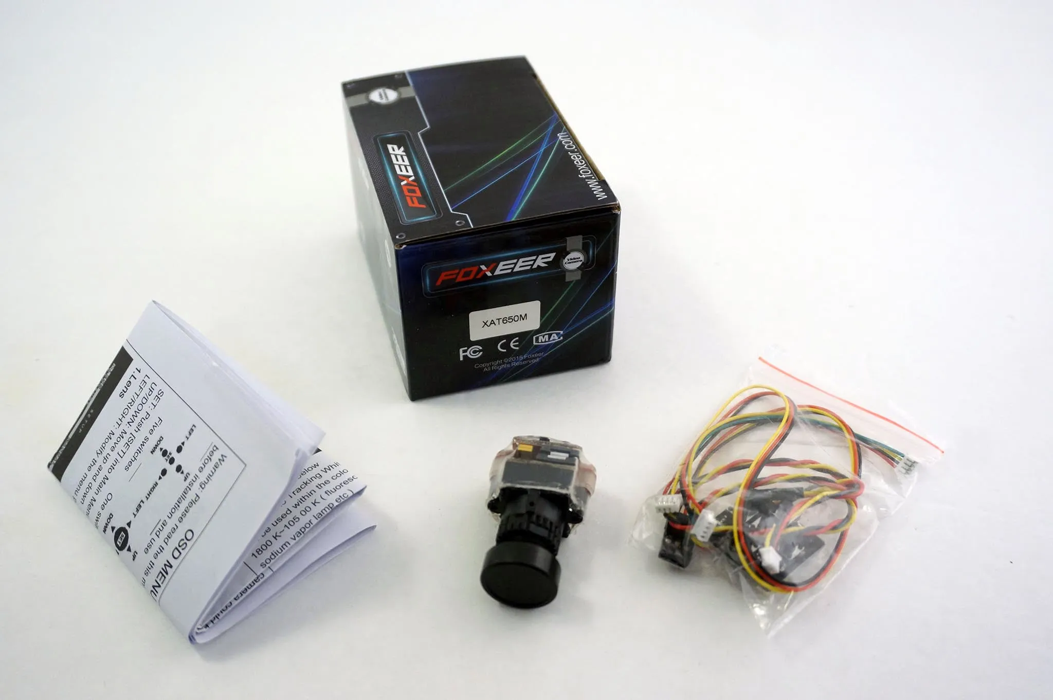
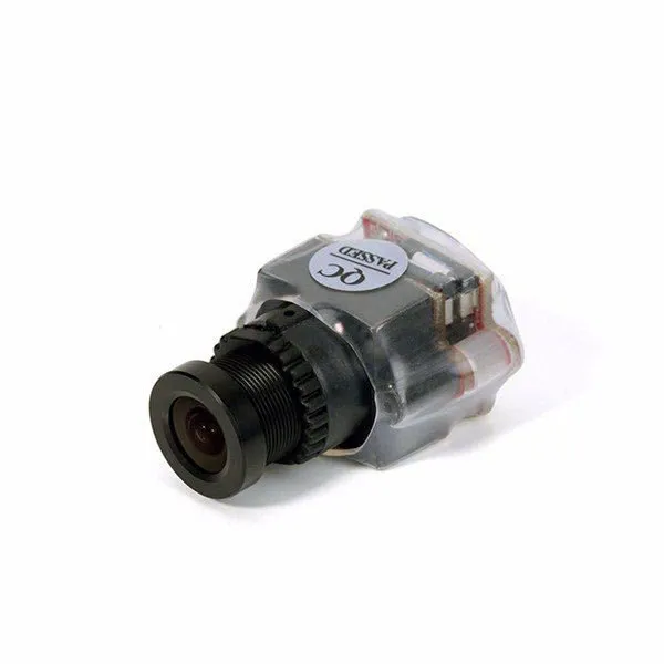 | Camera: FOXEER HS1177M 600TVL HAD II CCD PAL NTSC 2.8mm IR Blocked Mini FPV Camera 5V-22V |
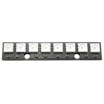 | RGB Led Strip |
Here’s an alternative, lower cost camera: 800TVL 1/3 CMOS 120 Degree 2.8mm lens FPV Camera 3.3-5V NTSC PAL
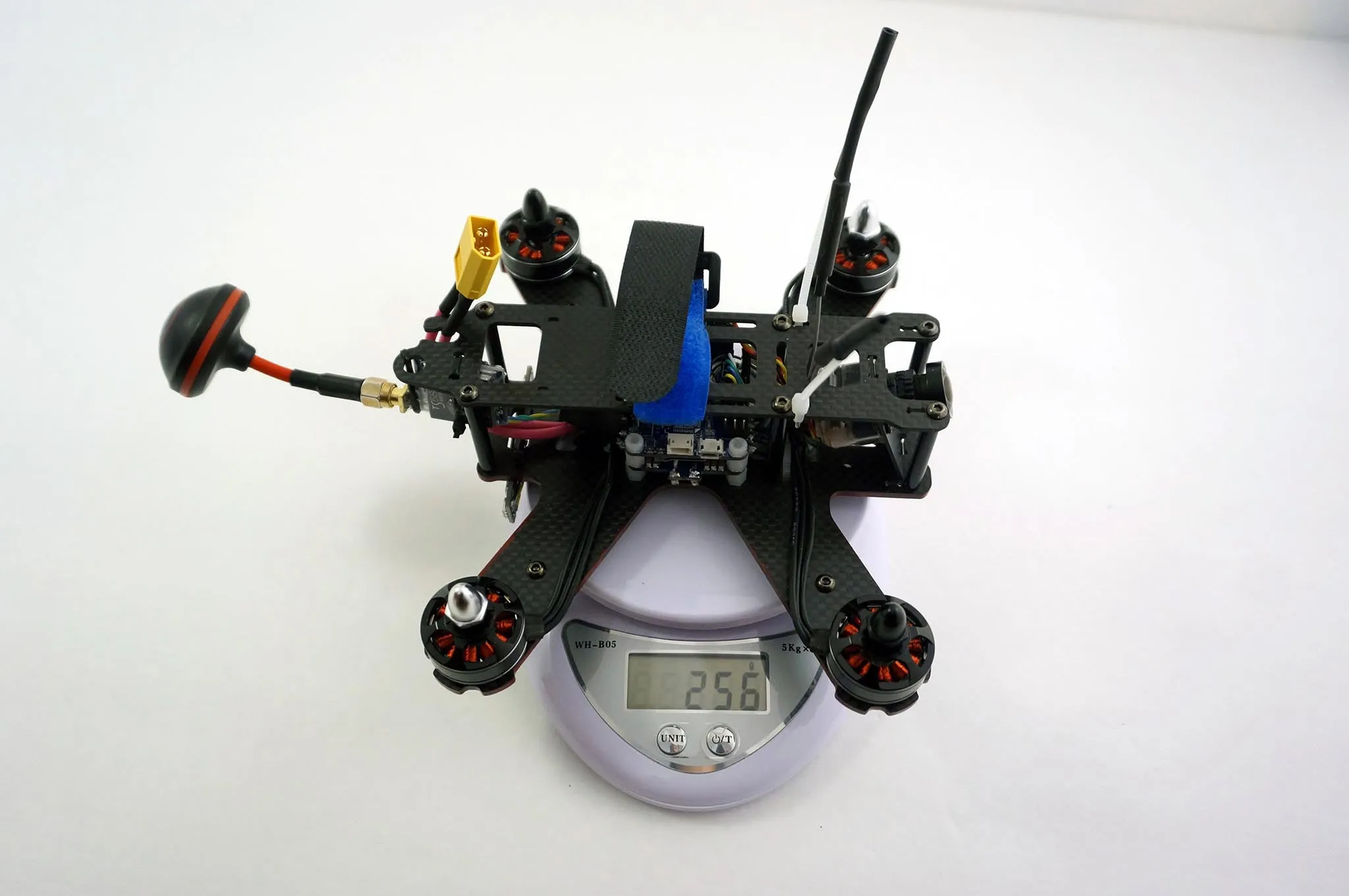
Everything for the quad is listed above, except the transmitter and receiver, battery and charger is included in the kit! You’ll also want some good goggles if you’re just getting started.
Let’s start building!
Review
The OmnibusF3 flight controller is an awesome F3 flight controller with a MAX7456 OSD chip directly connected to the flight controller, so it can be configured from the BetaFlight configurator.
I have a prototype OmnibusF3 flight controller, production boards are gold plated.
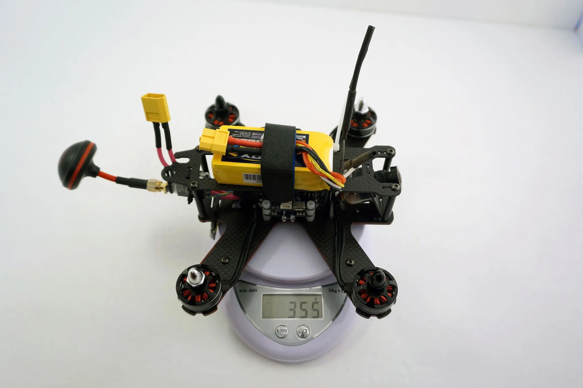
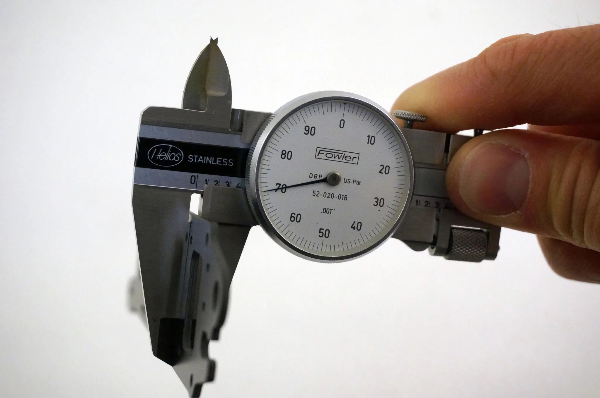
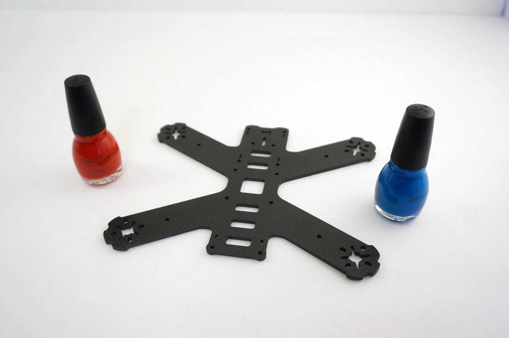
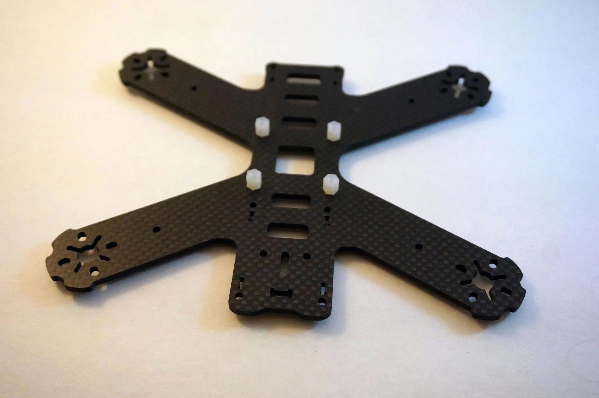
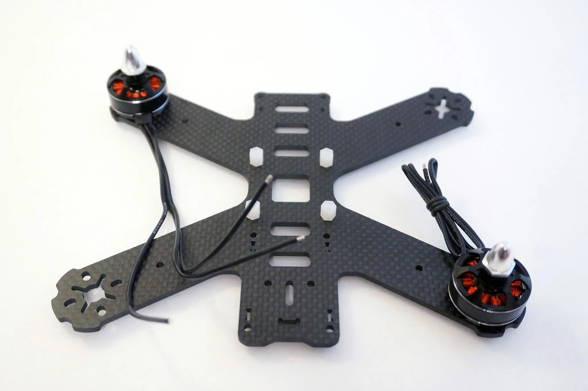
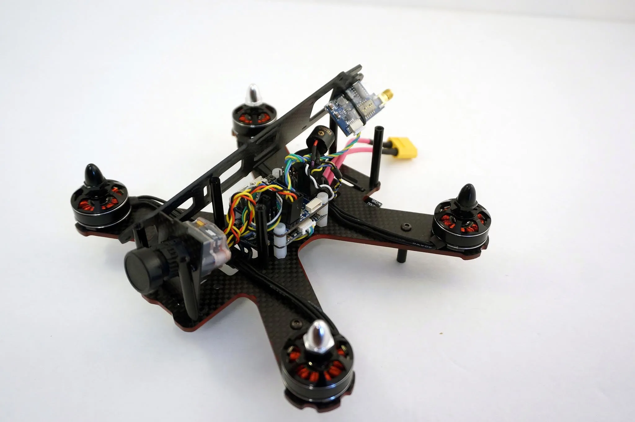
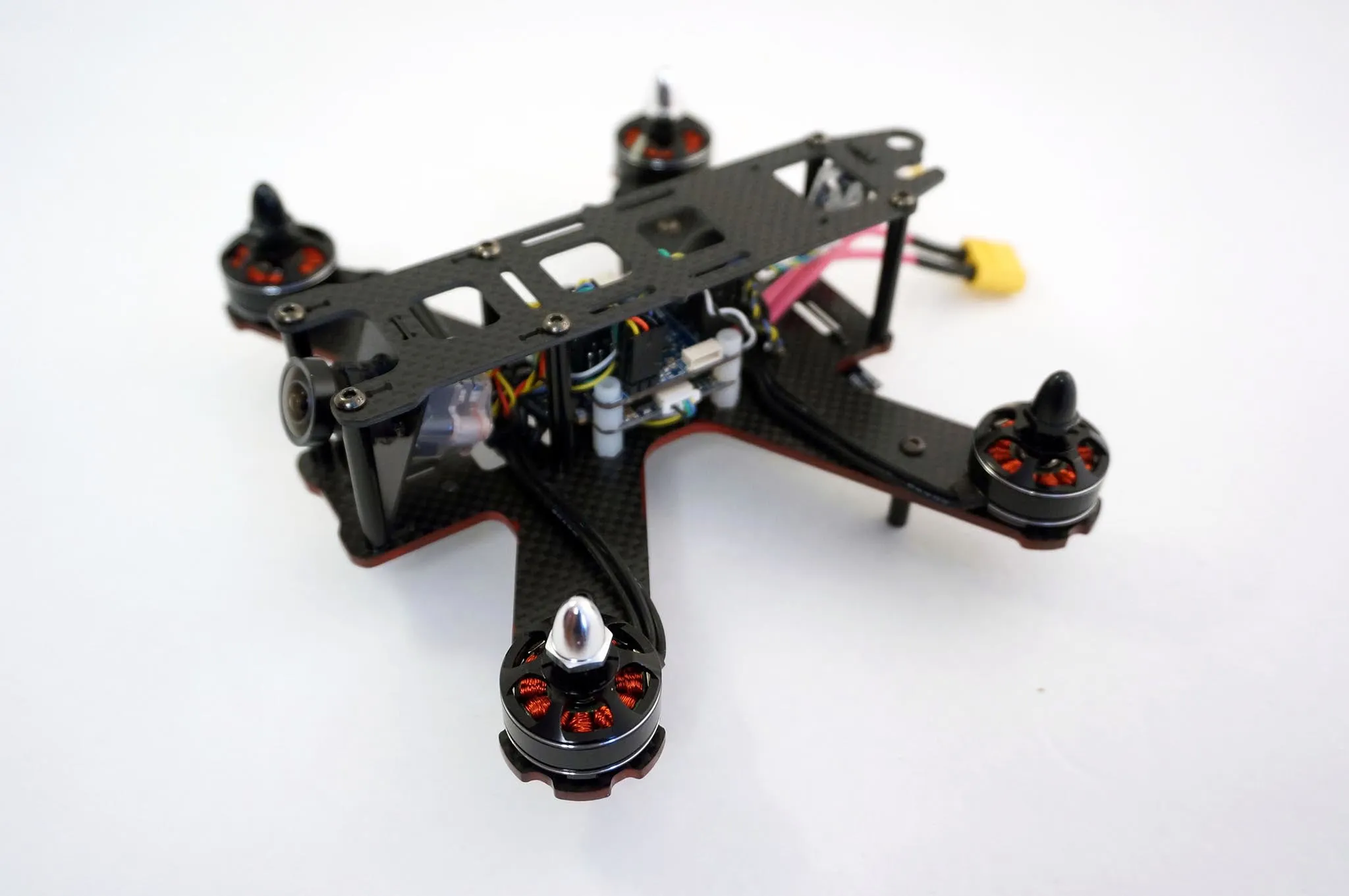
The frame is well built, high quality carbon fiber. I only have metric calipers, but I’ll convert for you.
Main body plate is 3.175mm.
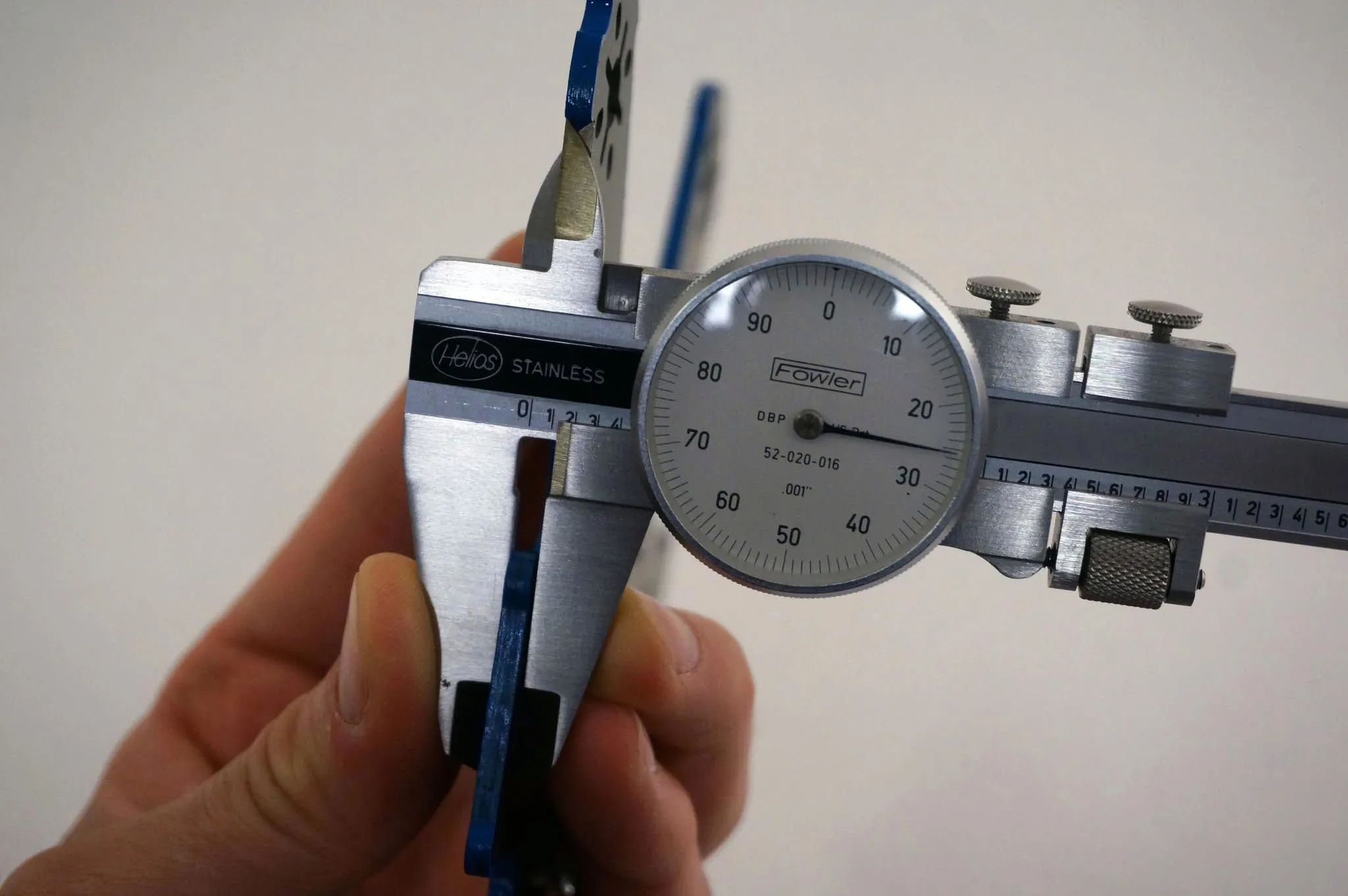
Side plate is 1.07mm.
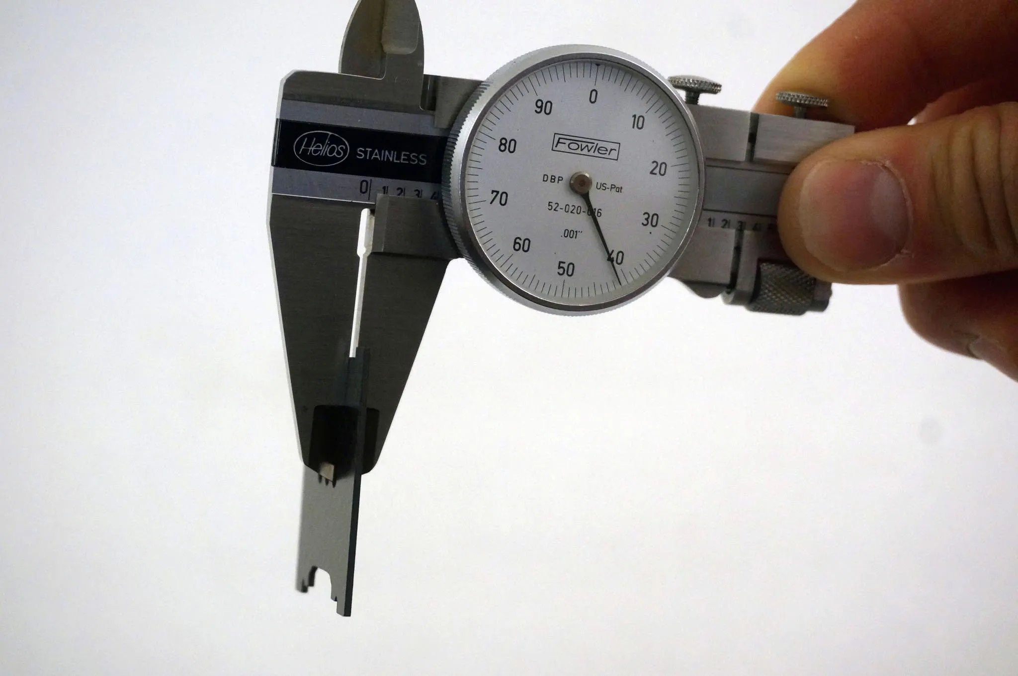
Top plate is 1.77mm.
I used some nail polish to seal the edge of the frame.
The Micro Titan 2204 Motors are awesome. They would be slightly better if they did not use clockwise and counter-clockwise shafts, but lock nuts instead. Not a big deal, because now we can buy some CW/CCW locknuts in case you lose one.
Build Guide
Let’s start with the frame
Frame
Let’s build out the frame a bit first. Attach some nylon standoffs.
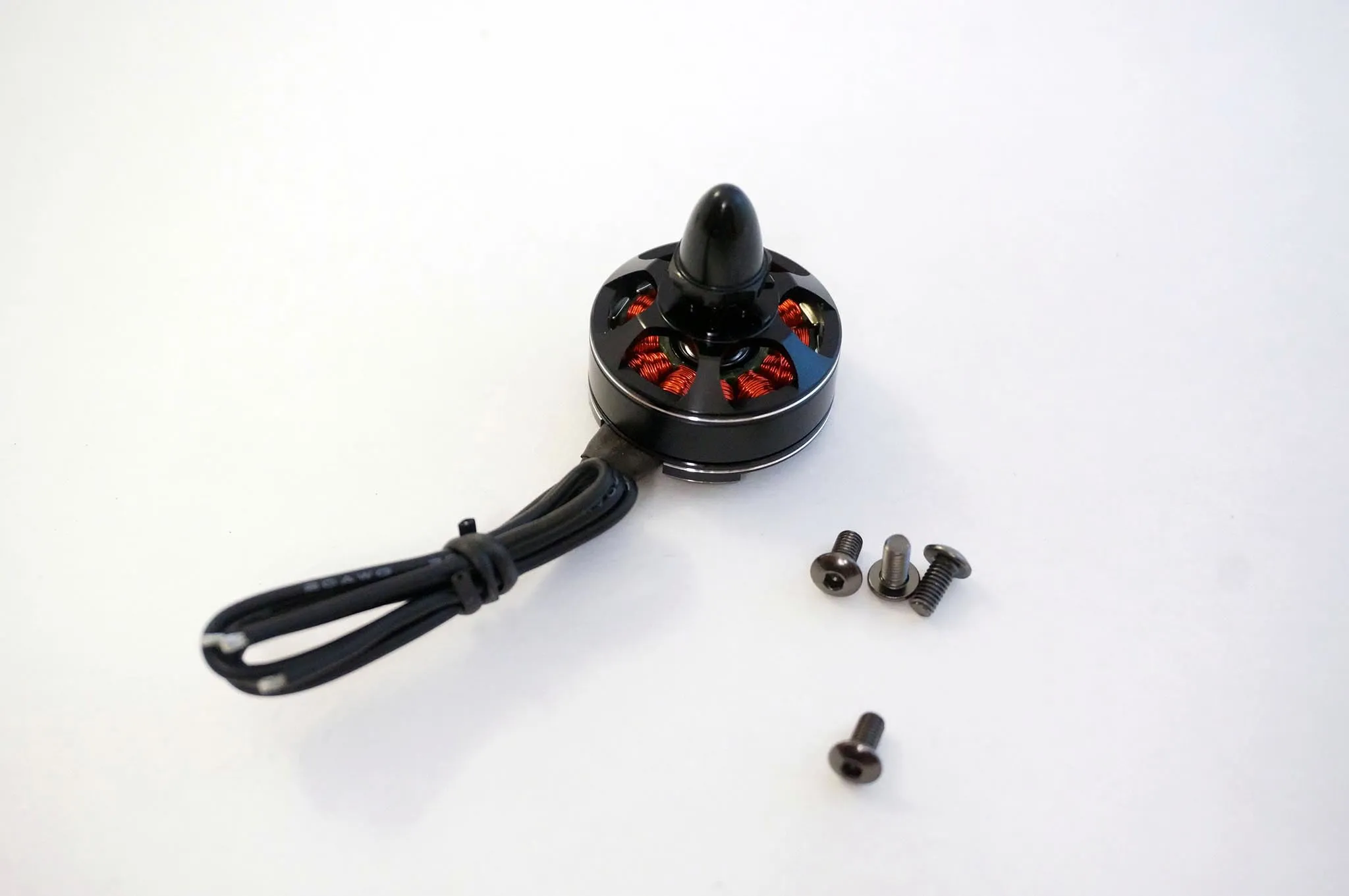
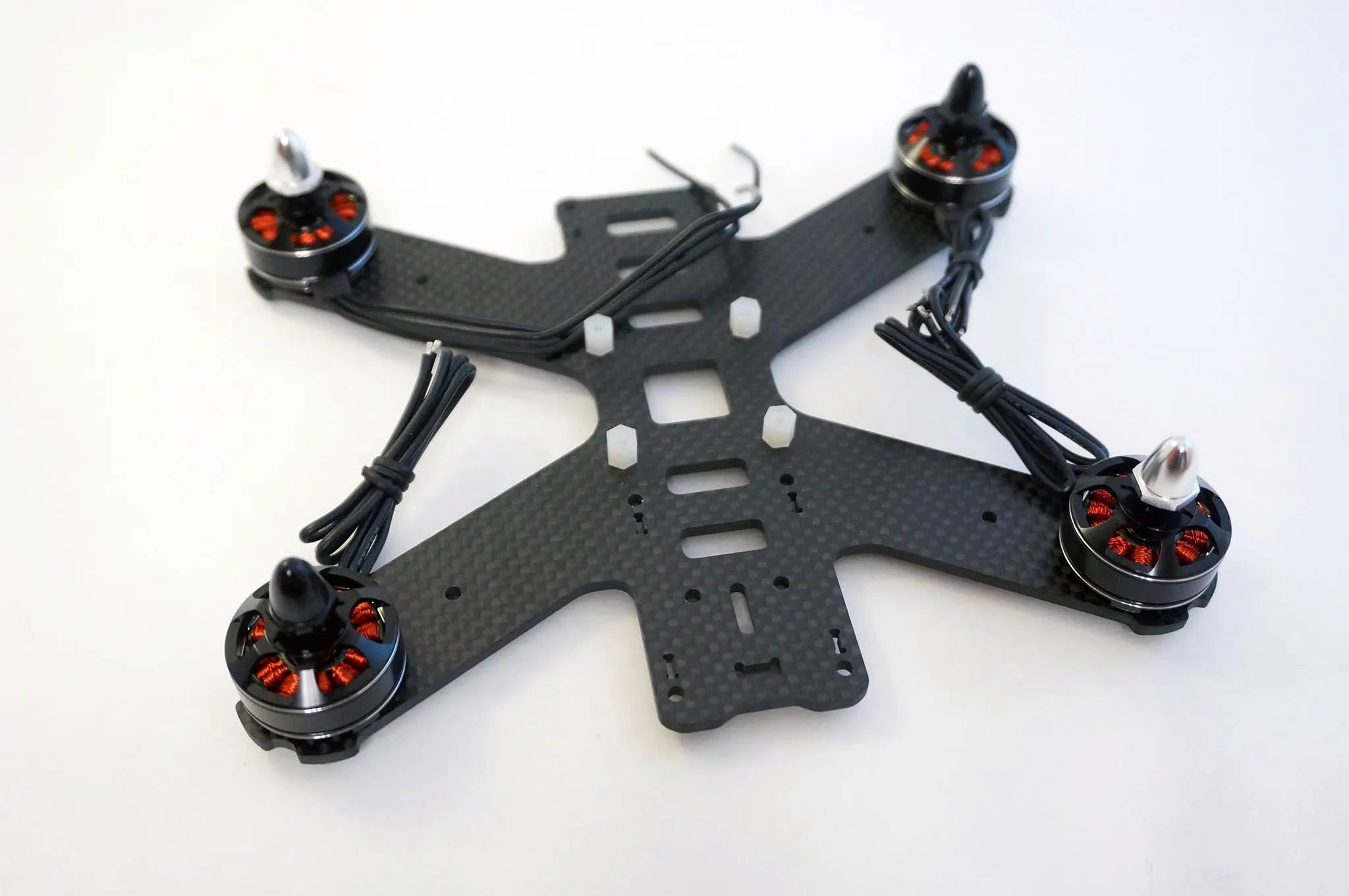
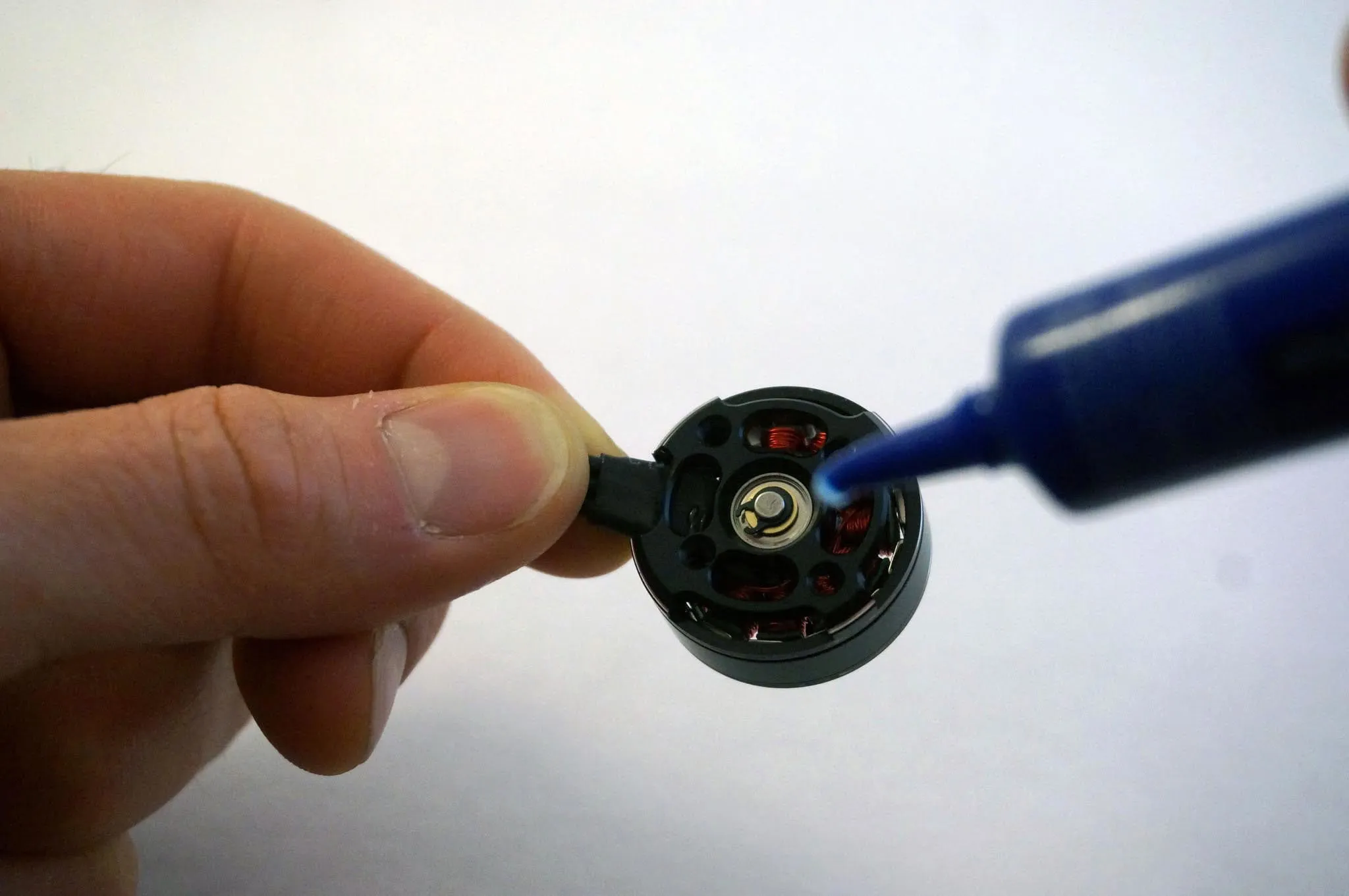
Use some blue thread locker to attach the motors.
The motors have reverse-threaded shafts, which I’m not a fan of. It would be better if they were all threaded the same way and used lock nuts, but it doesn’t really matter. Just make sure you put the motors with sliver prop nuts on the bottom right and top left.
Attach the motors with black prop spinners in the other corners.
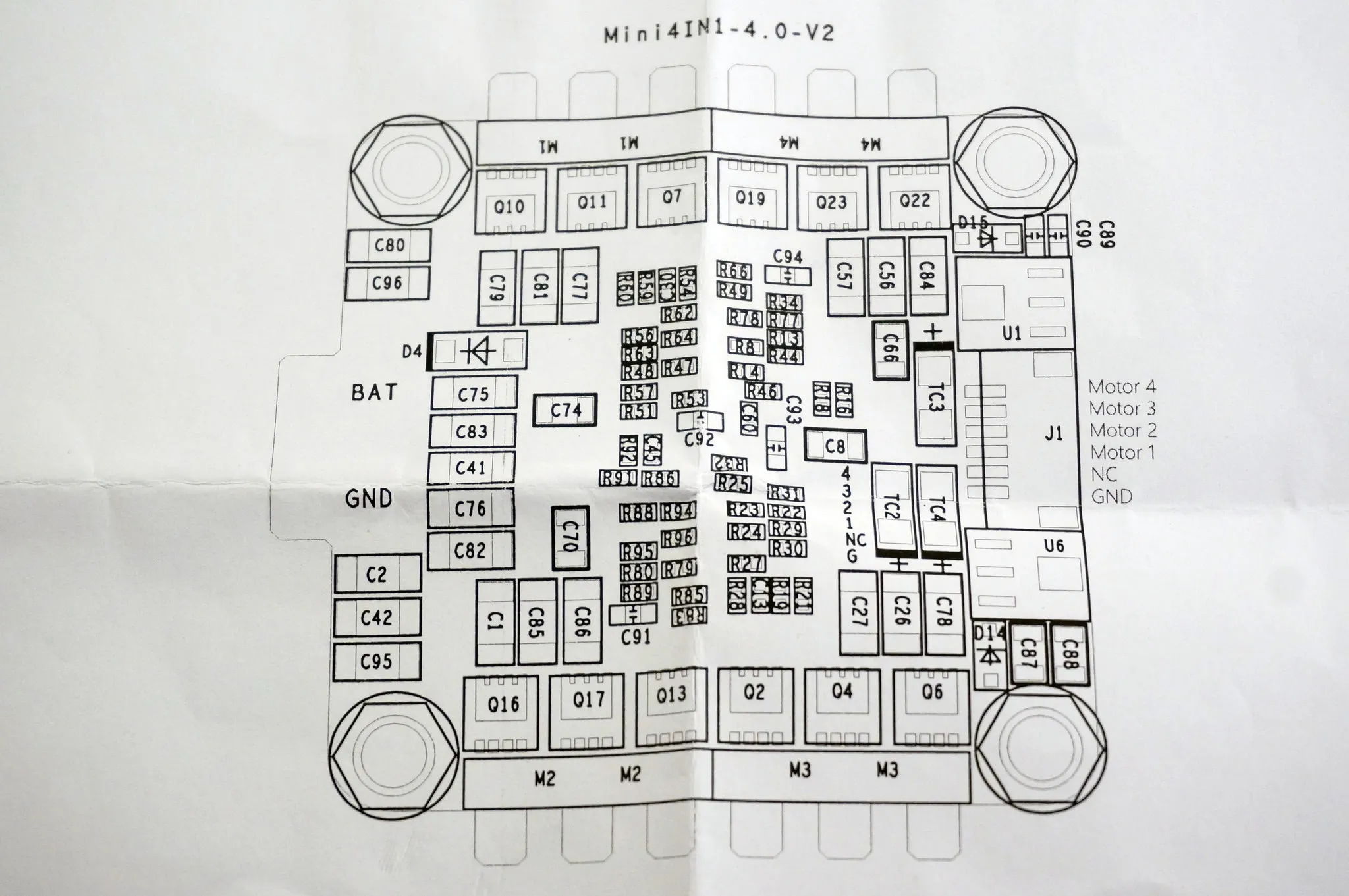
ESCs
Next, let’s prep the ESC. We can see the pro edition uses the SiLabs 396 MCU:
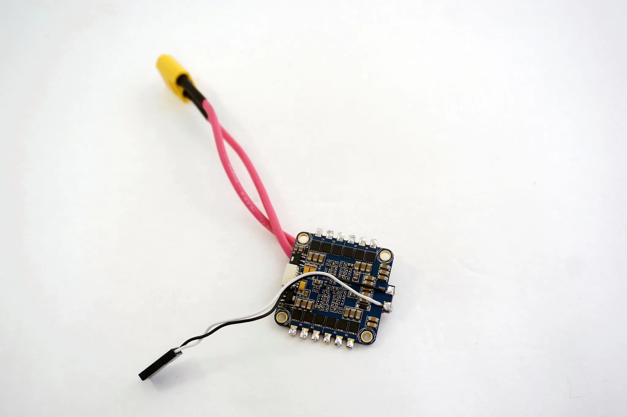
Solder an XT-60 or deans battery lead on one side of your Typhoon ESC and a smaller servo plug on the other side. One is for the battery and the other side will connect to the flight controller.
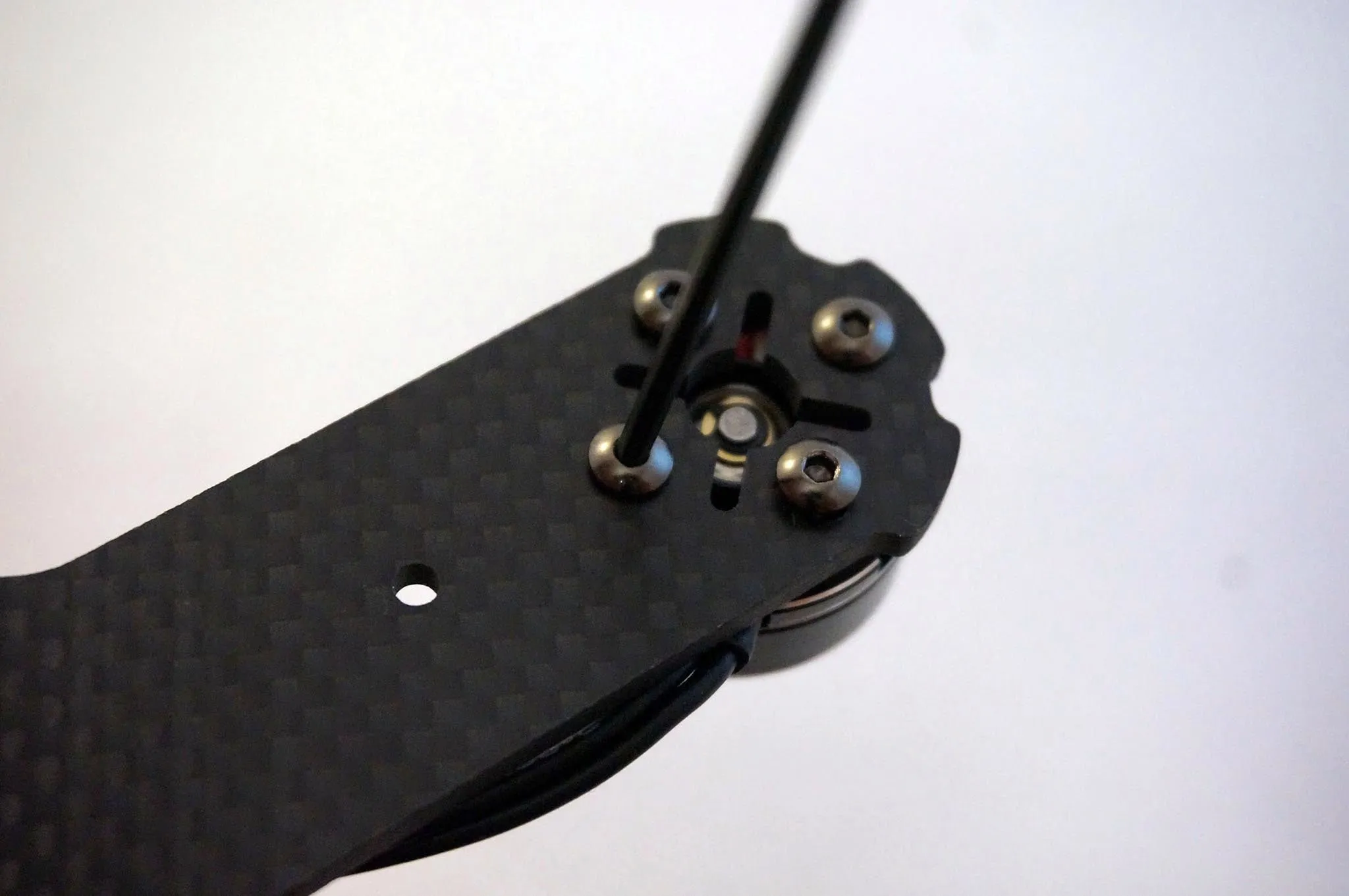
Install the Typhoon ESC with another set of standoffs.
Typhoon motor order
Note that when connecting the Typhoon to a BetaFlight flight controller, the Typhoon motor order is slightly different than the motor order that BetaFlight expects. Motors 3 and 4 on the typhoon are swapped, relative to the BetaFlight motor order.
Here is the expected motor order:

Here is the motor order on the Typhoon ESC:

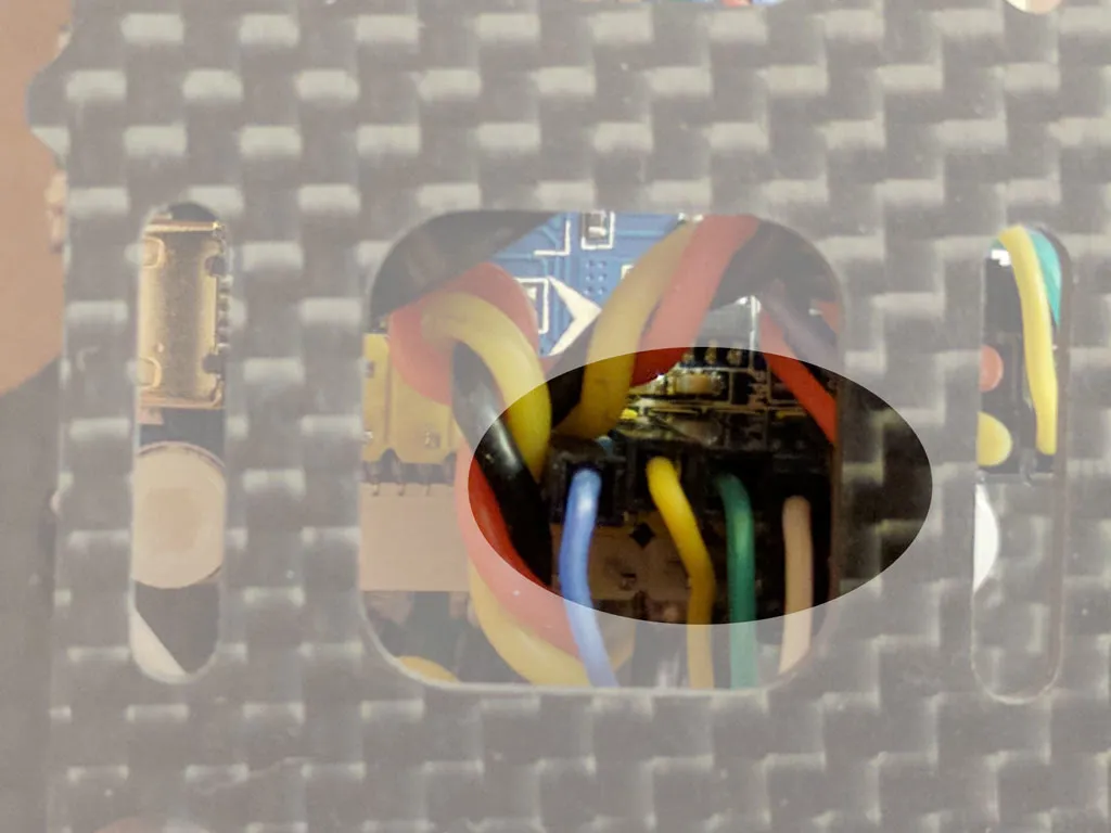
Here’s how mine looks plugged in, pinout from the ESC:
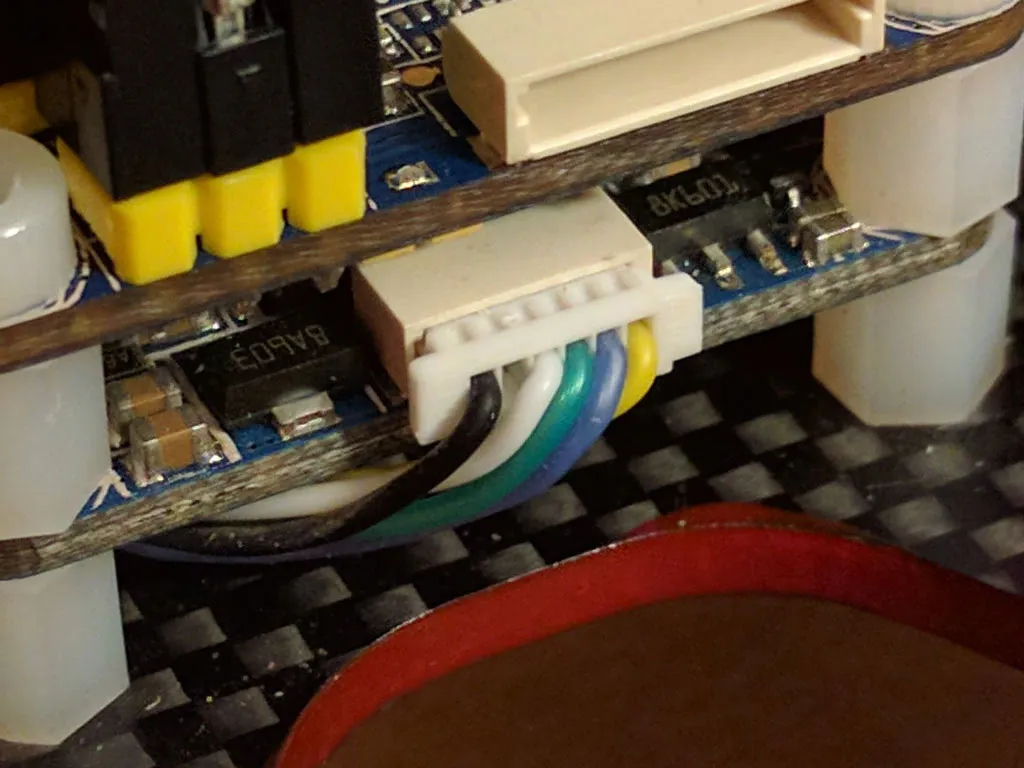
And the flight controller side:
Flight Controller
Start by soldering the pin headers onto your flight controller. A flux pen will make this easier, but is not required.
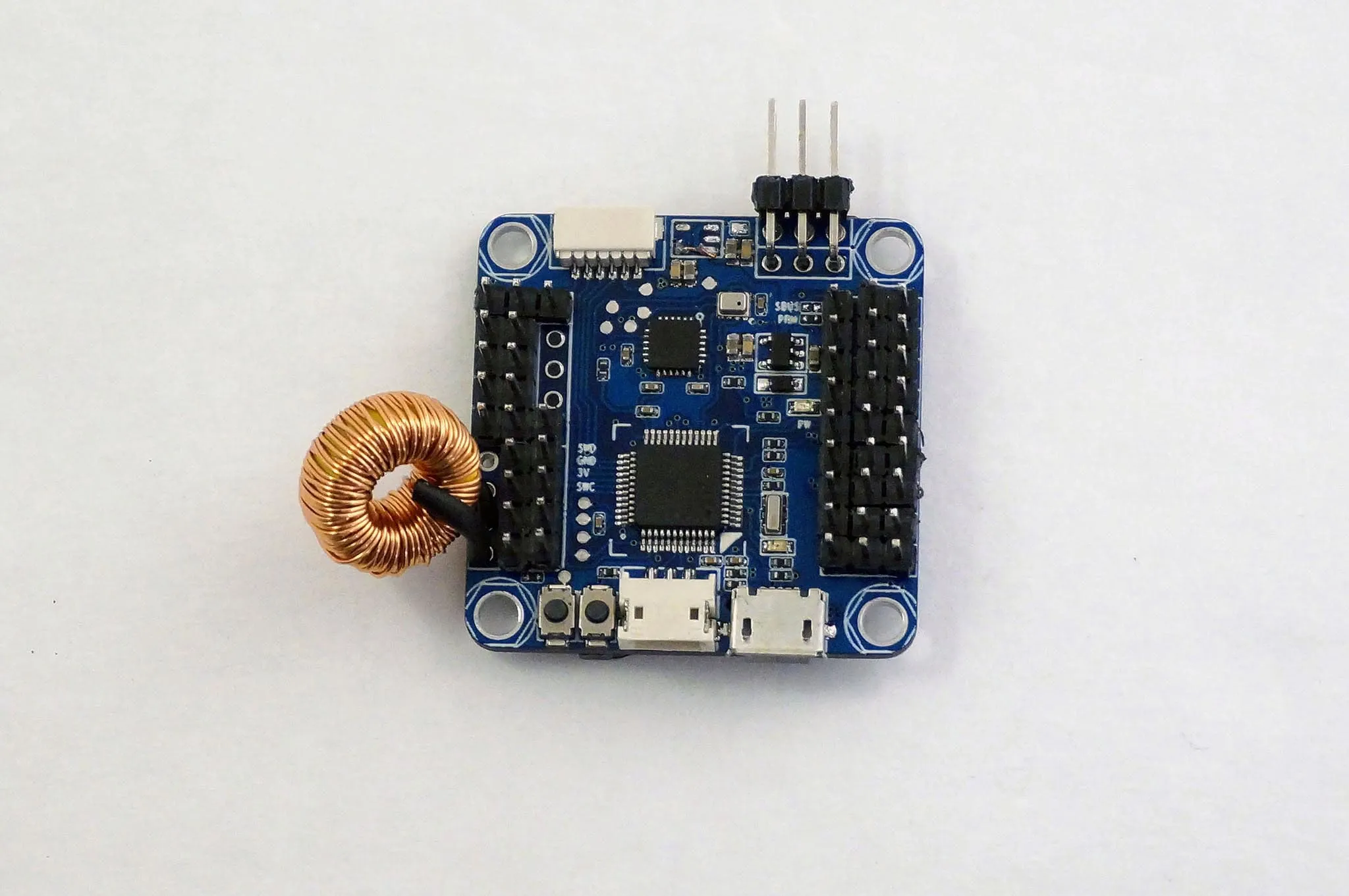
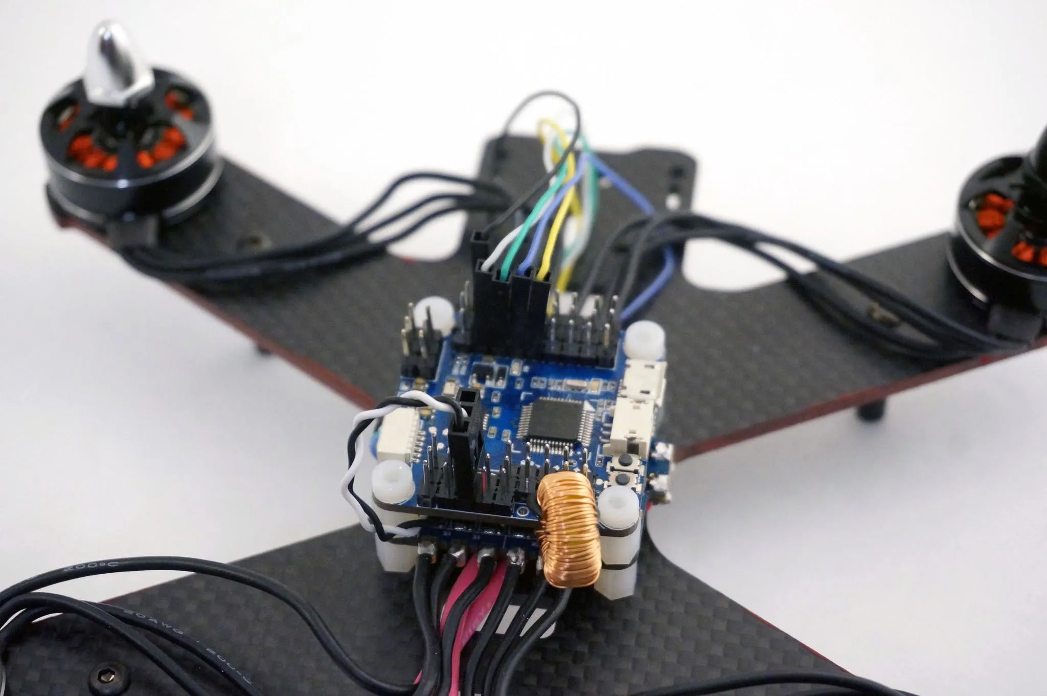
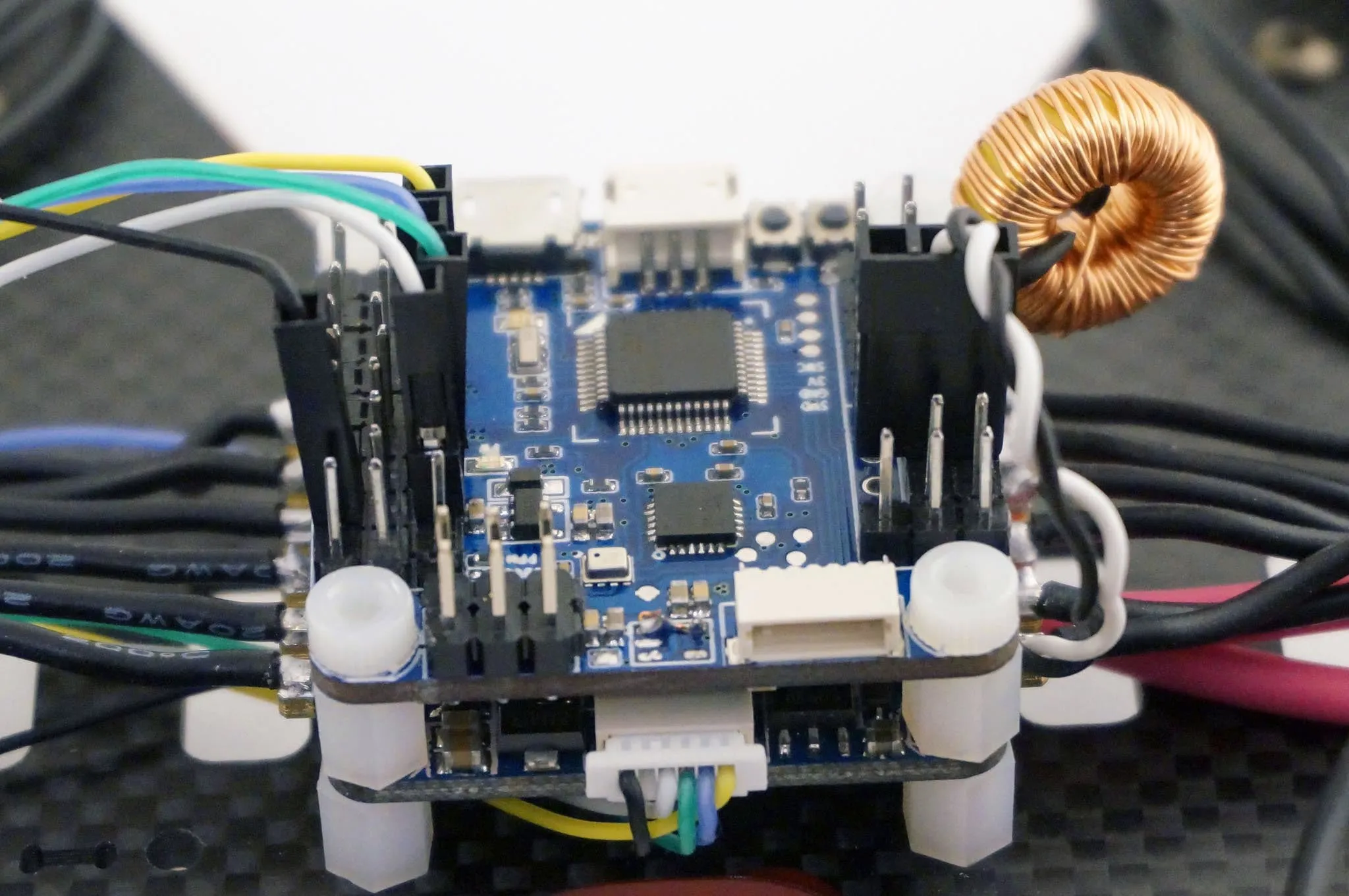
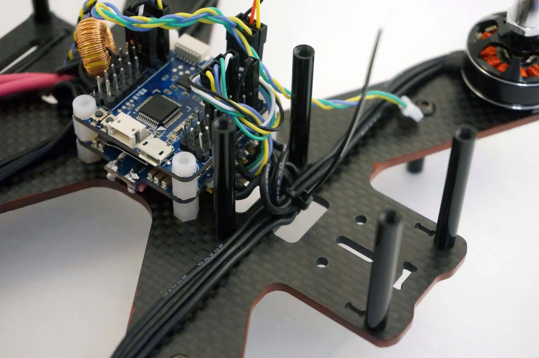
Here is the board with pins populated. I’ve solder an inductor as described above, to power the video camera and transmitter. This isn’t necessary, but there also isn’t any downside, except weight.
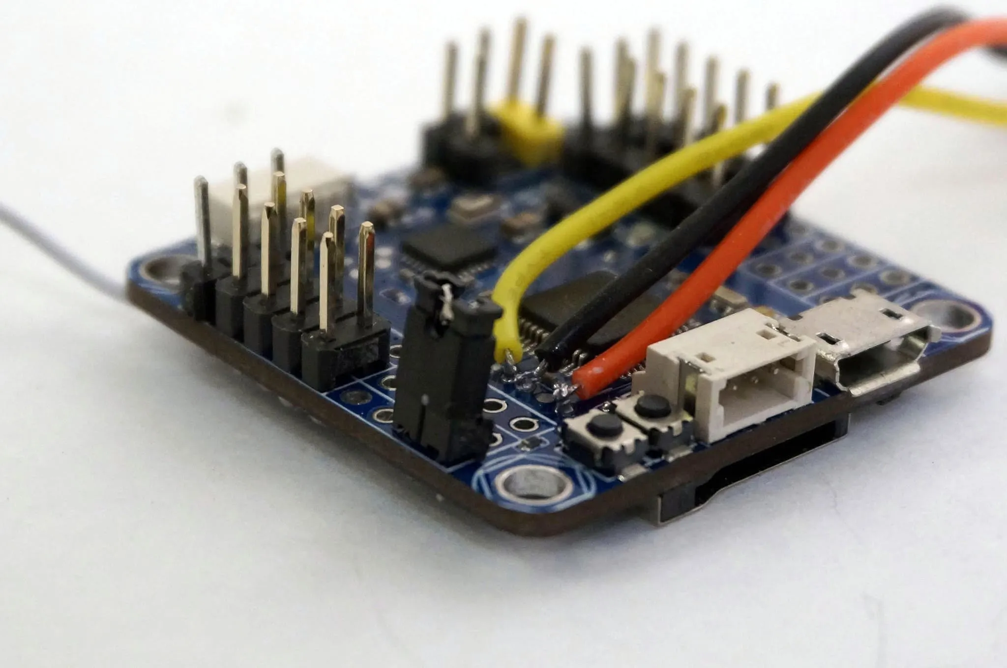
Alternatively, just put some pin headers on and use a jumper, like this. On a side note, those wires I have soldered straight to the board are for the SWD debugging port. You won’t need to attach those unless you want to debug the code.
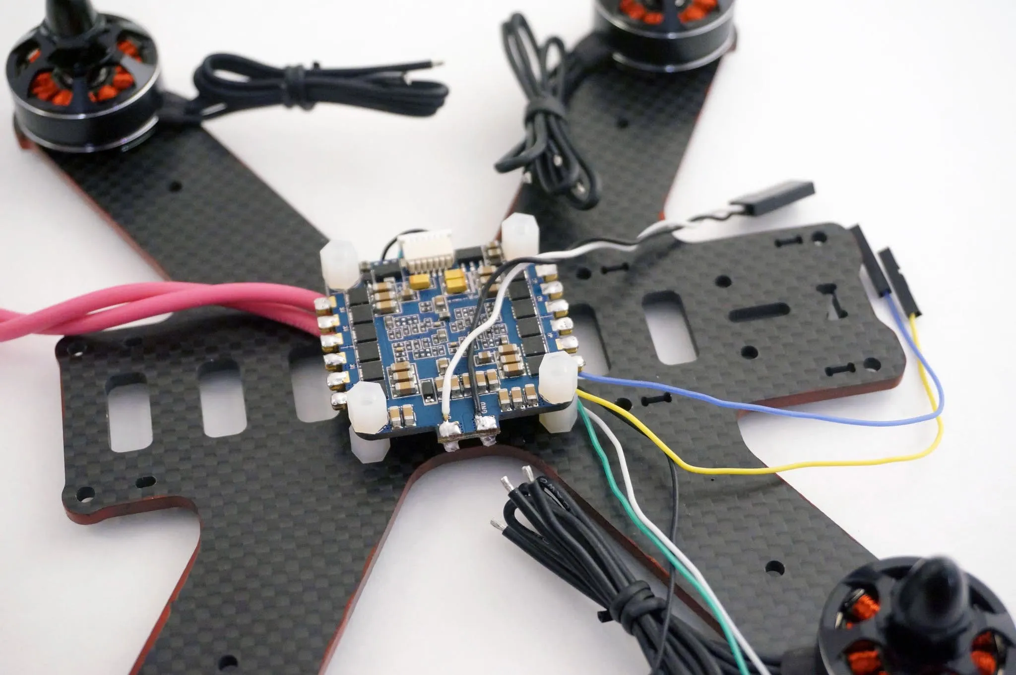
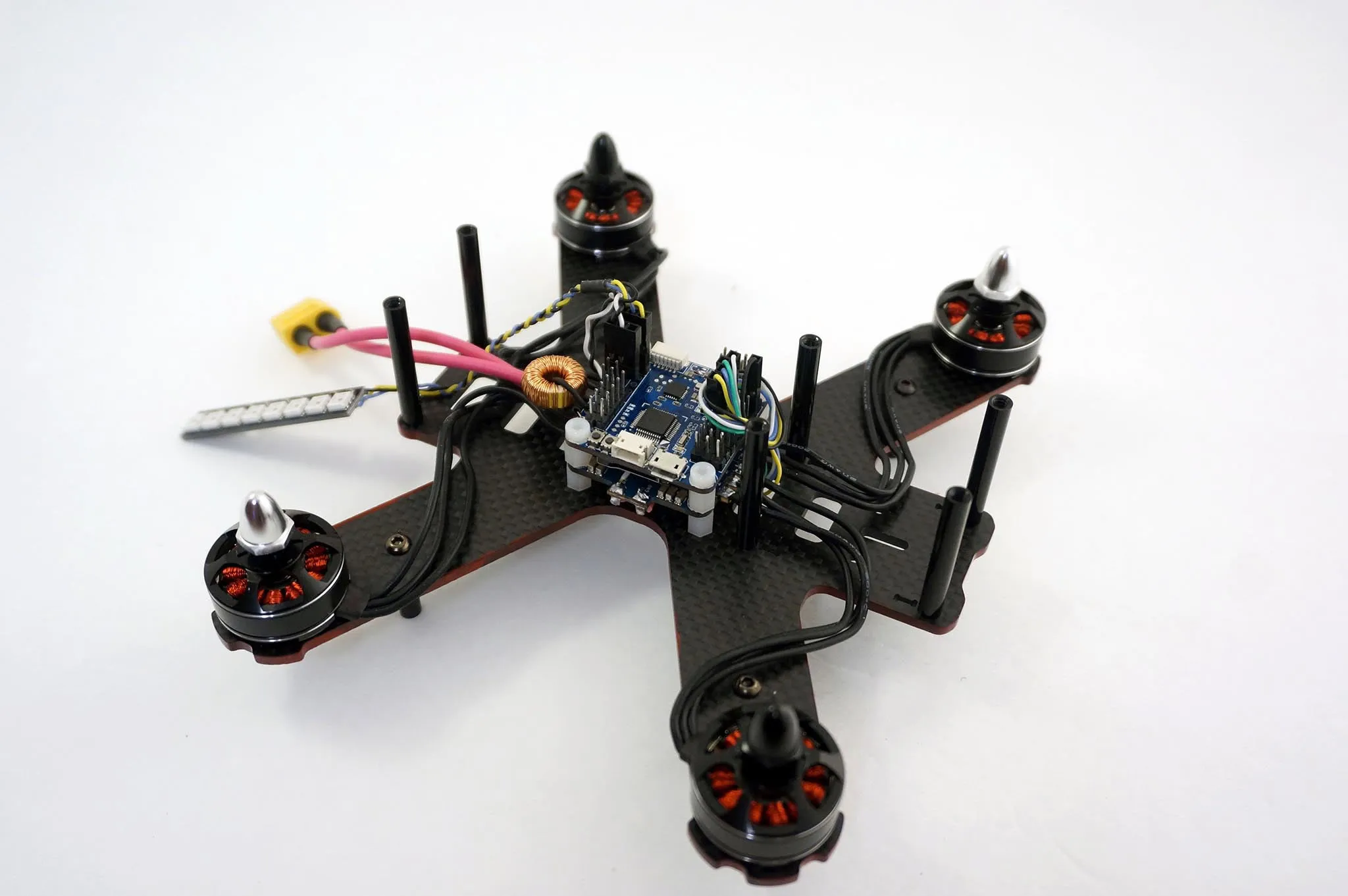
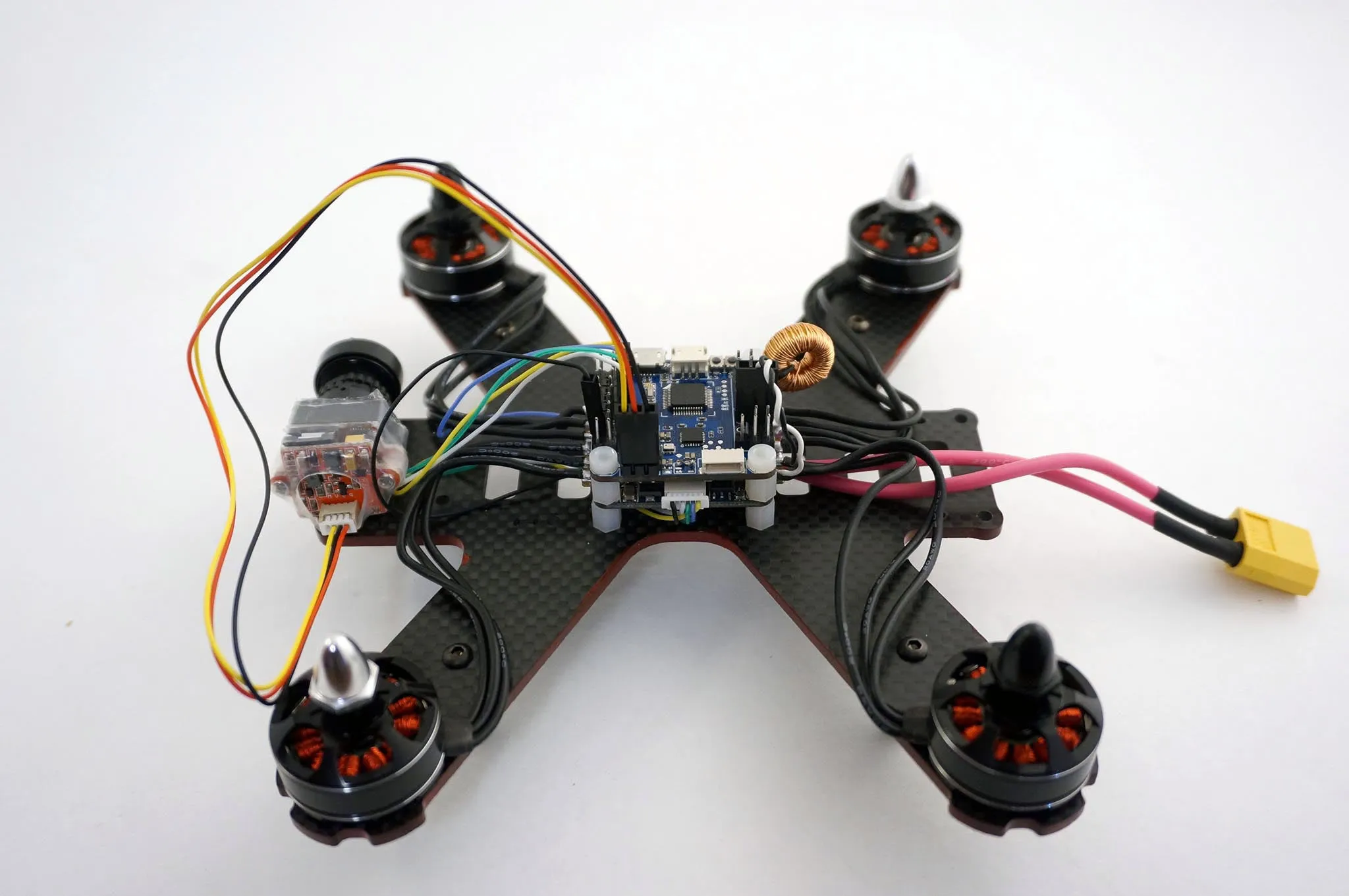
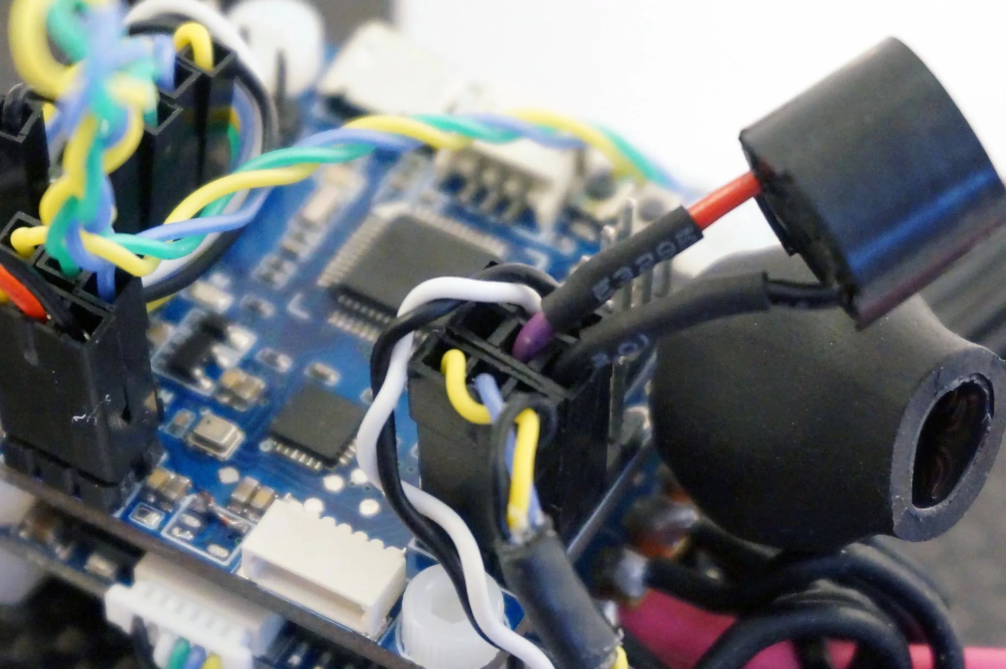
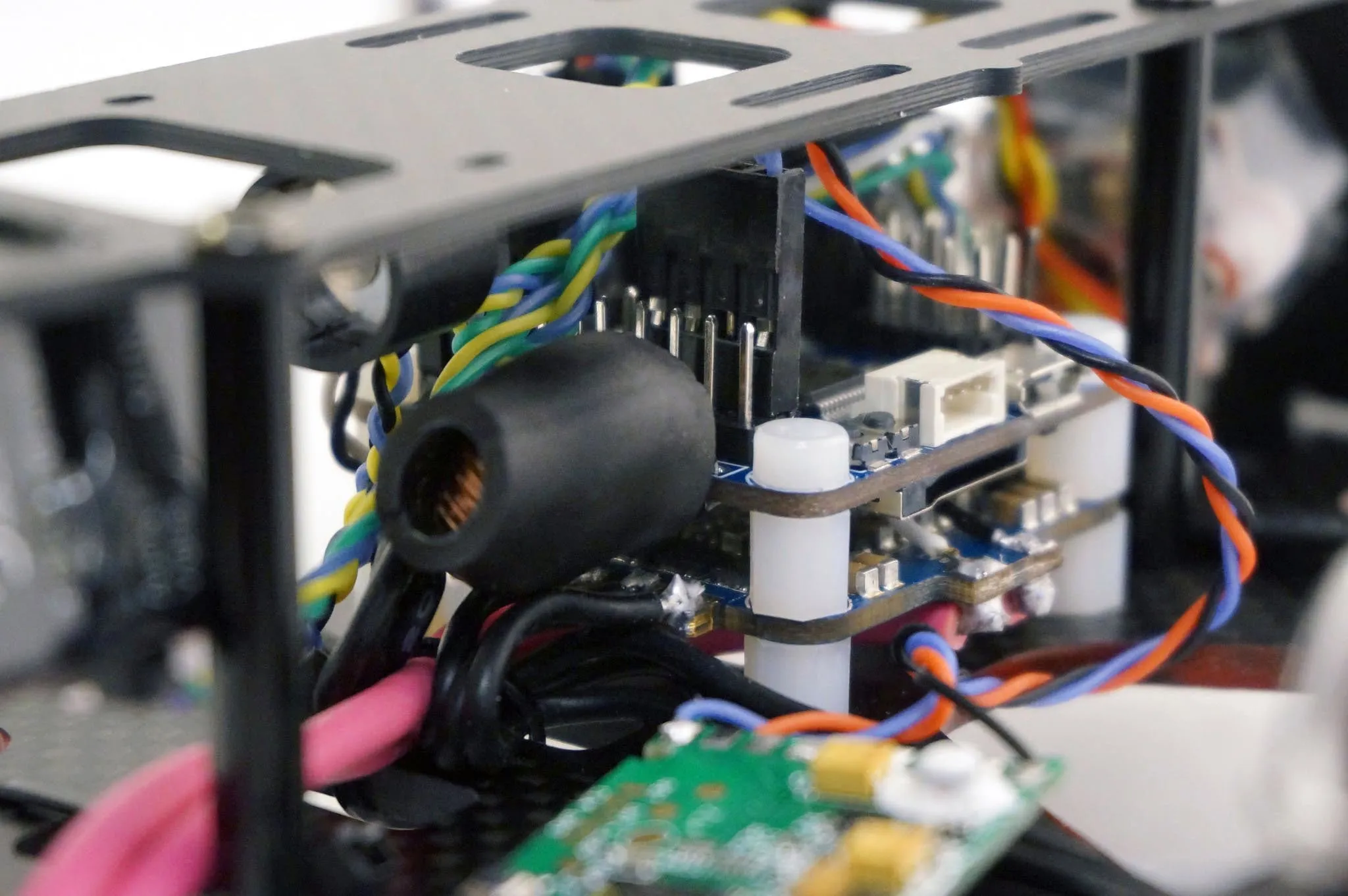
Let’s plug in the flight controller. Here is how the ESC is connected. PWM inputs in the foreground and power (VBAT) in the background.
Here’s what it looks like with the flight controller mounted. The inductor looks huge! It’s wayyyy overkill.
Updating BetaFlight
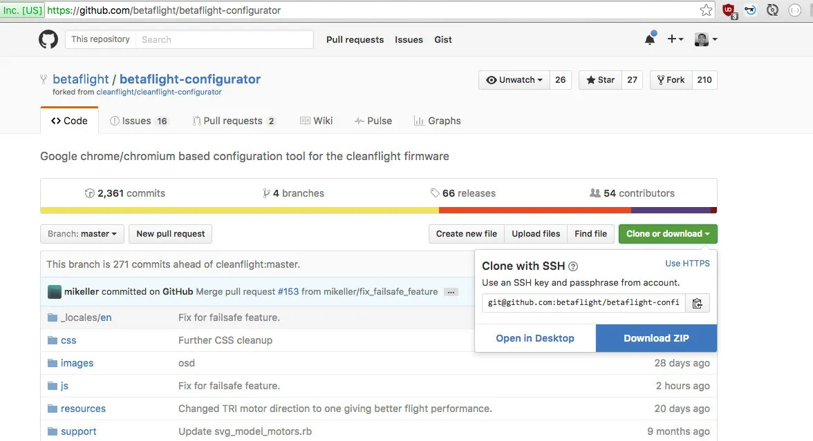
Install BetaFlight by downloading the configurator or get the latest version of the configurator as follows:
Go to https://github.com/betaflight/betaflight-configurator
Click Clone or download then Download ZIP
Then open chrome://extensions, check Developer Mode
Click Load Unpacked Extension
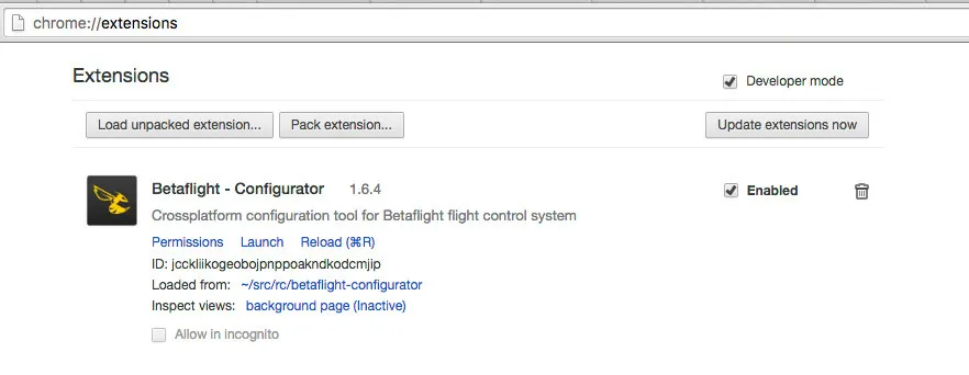
Pick the folder you downloaded and unzipped, then launch the configurator.
Then open the firmware flashing tab, pick the board and the latest BetaFlight version. Change the Manual baud rate to 256000 as with all F3 flight controllers, then hit Load Firmware [Online] and Flash Firmware.
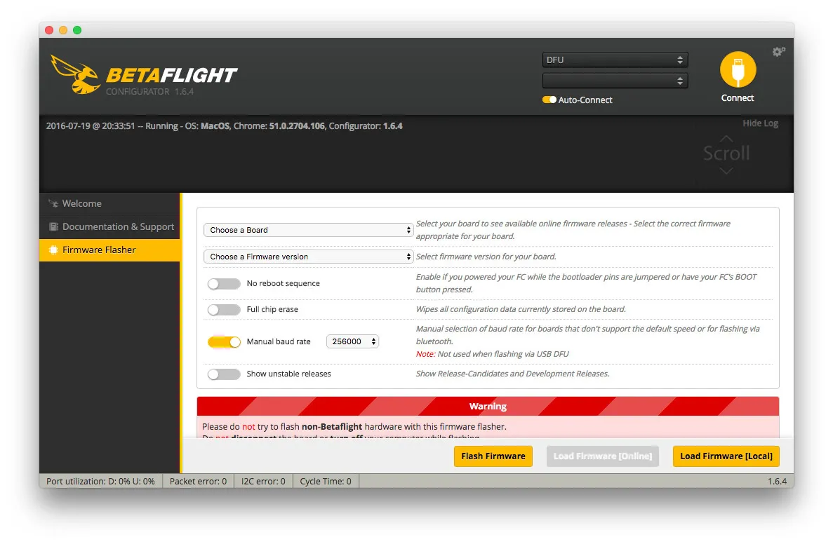
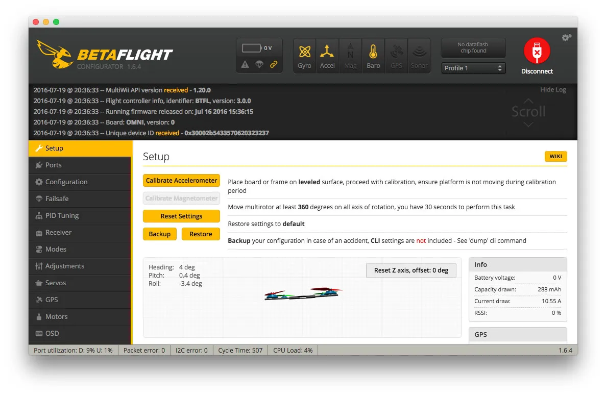
Then hit connect.
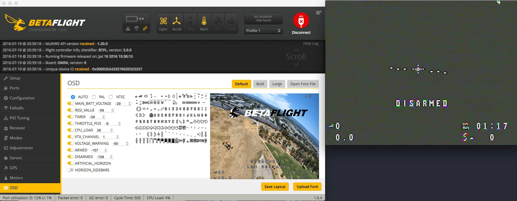
Open the OSD tab, pick the font style you prefer (from the upper right hand corner, I like bold) then click Upload Font`. The flight controller will reboot when the upload is complete.
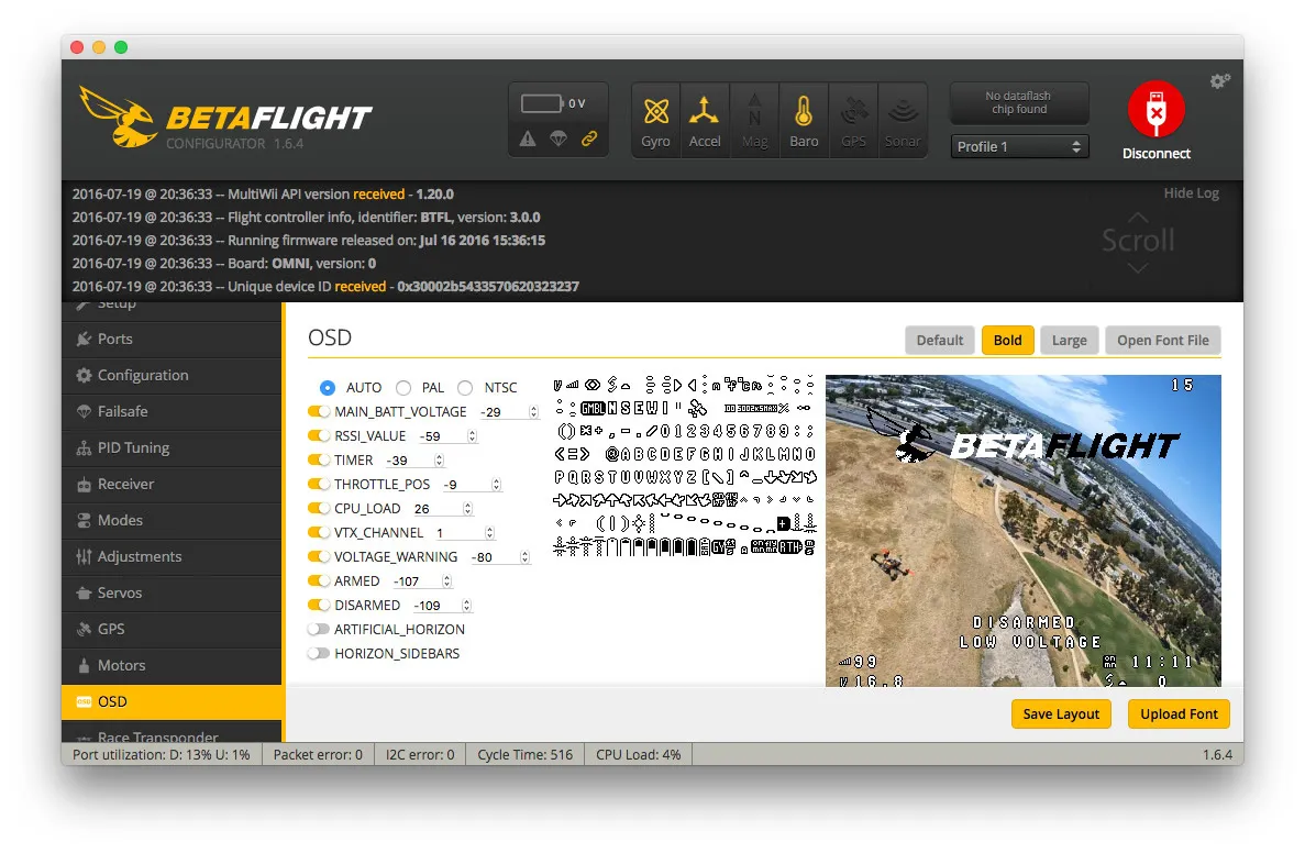
If you like to fly with an artificial horizon, go back to the OSD tab, enable it and hit Save. In this photo, I have the video from the OMNIBUSF3 being captured by my computer so you can see it:
Now double check your power connections, ensuring all grounds are connected to ground, the battery pin is correct and that 5v goes to 5v. Then plug in the battery.
Open the BetaFlight configurator and spin up each motor to ensure it is the correct location and spins the correct direction.
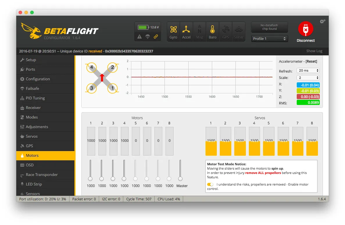
Now would be a good time to calibrate your ESCs as well. To do this, unplug the battery, slide the Master slider on the motors tab all the way up, plug in the battery. Wait for the beeping to stop, then slide the master slider all the way down. Wait for the beeping to stop then unplug the battery.
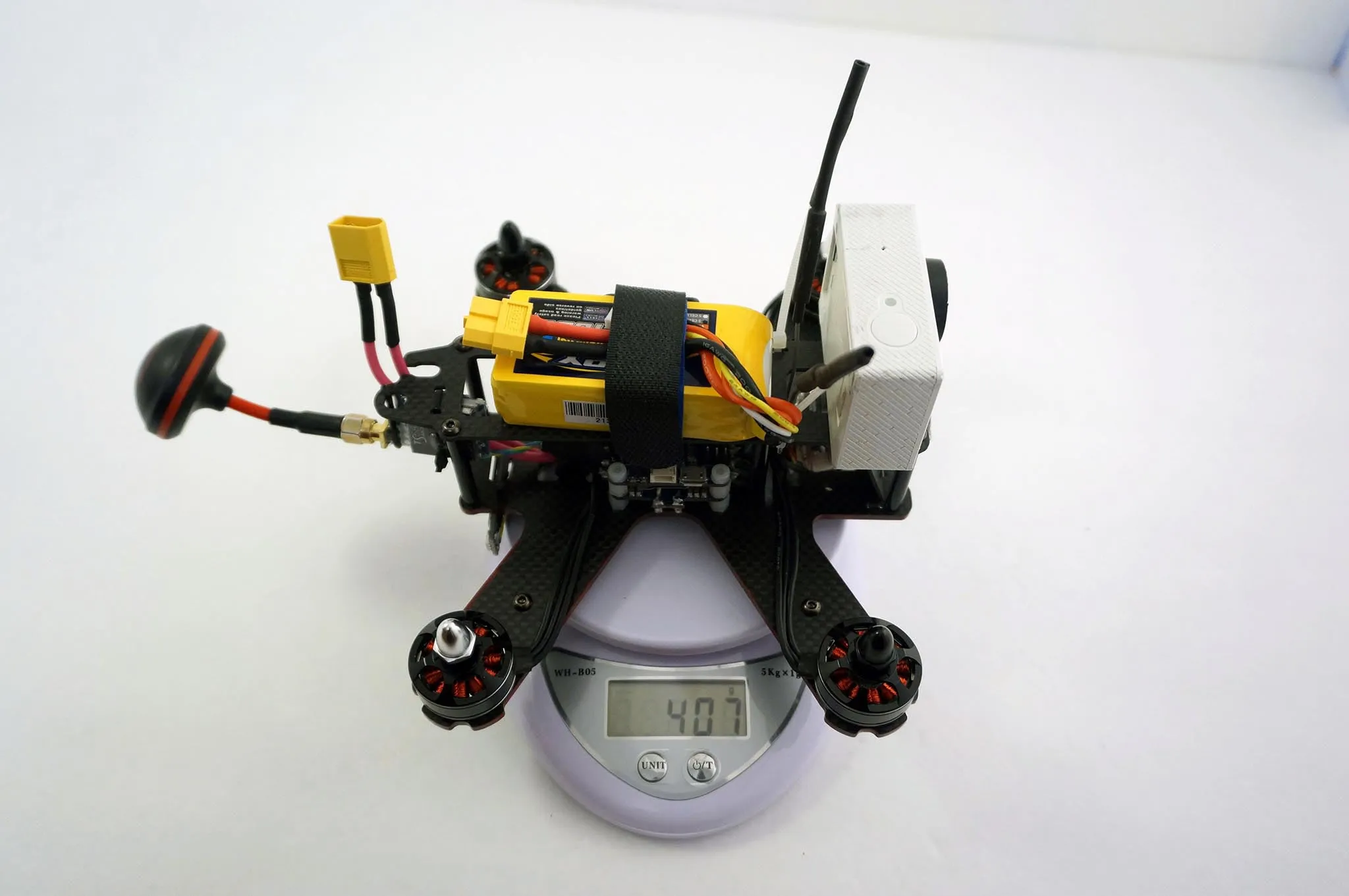
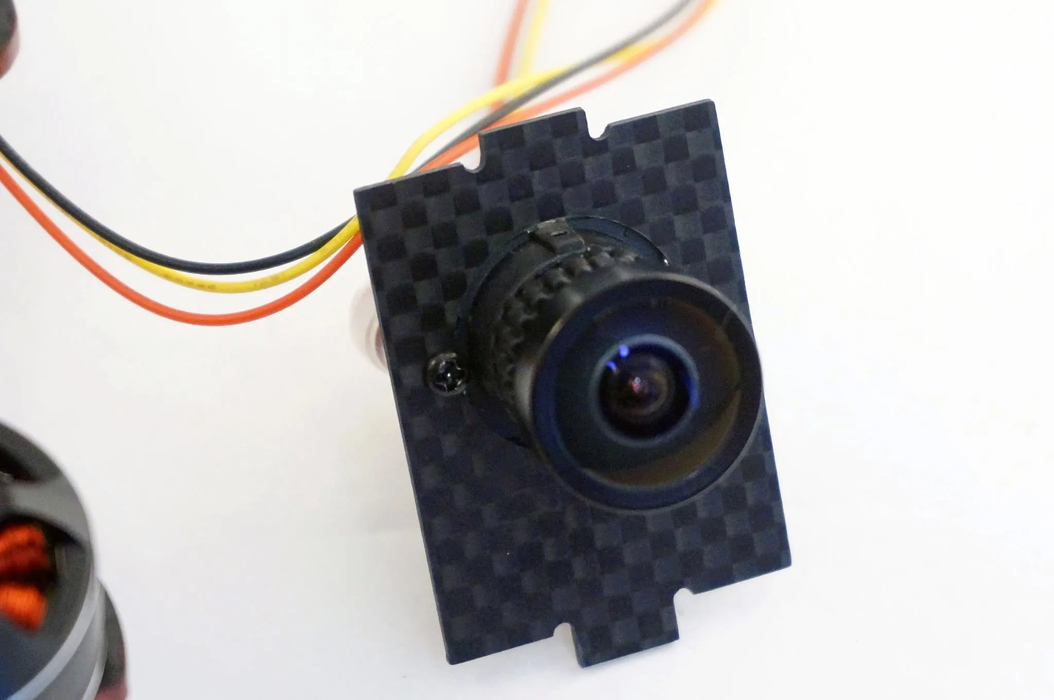
Camera
Let’s install the standoffs then get to the camera.
The camera comes with a manual and some buttons on a PCB to control the menu.
Here’s how you’ll attach the camera.
The Video Transmitter.
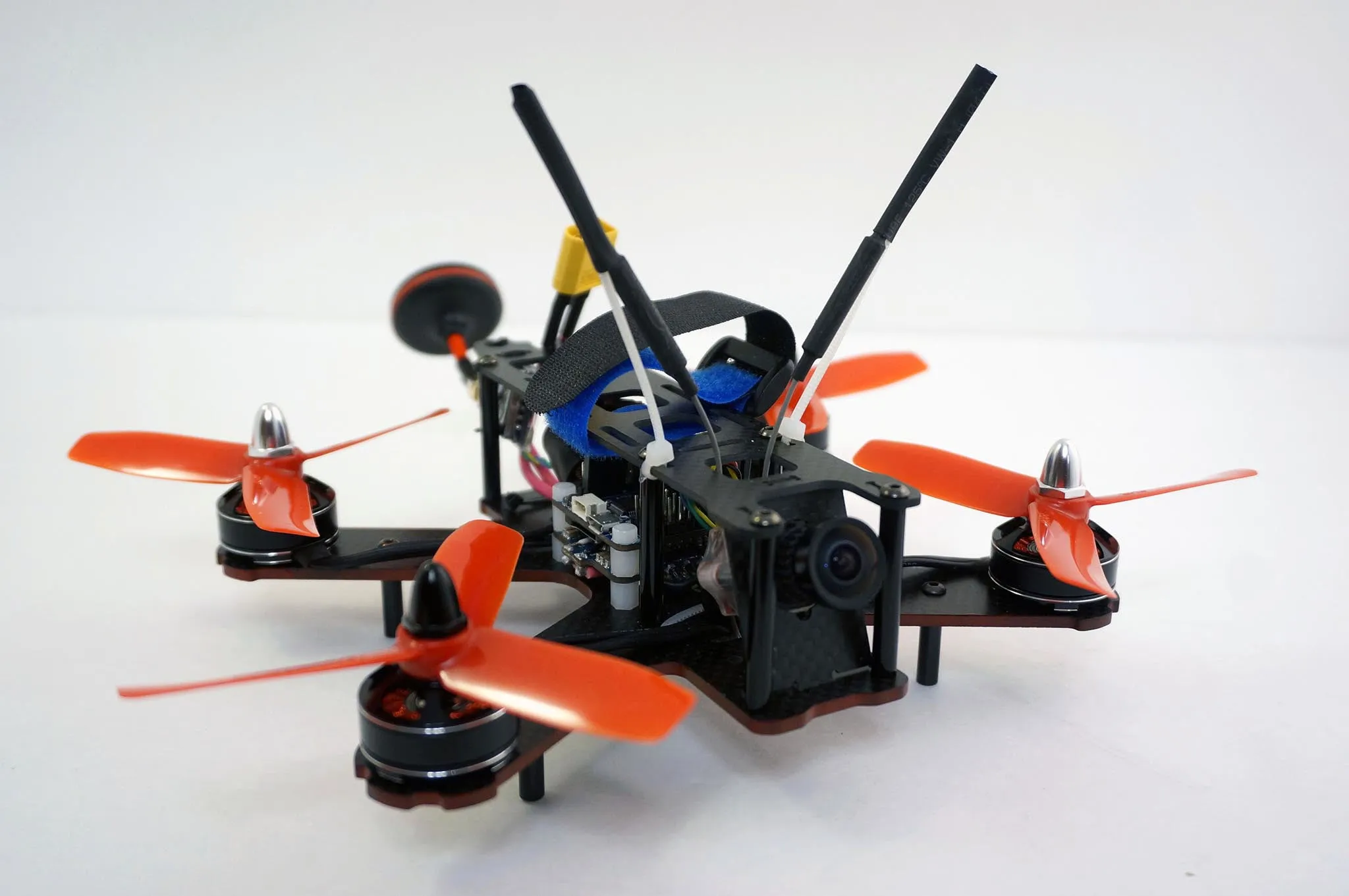
Final assembly
Tidy up the build, I’ll zip tie down the motors.
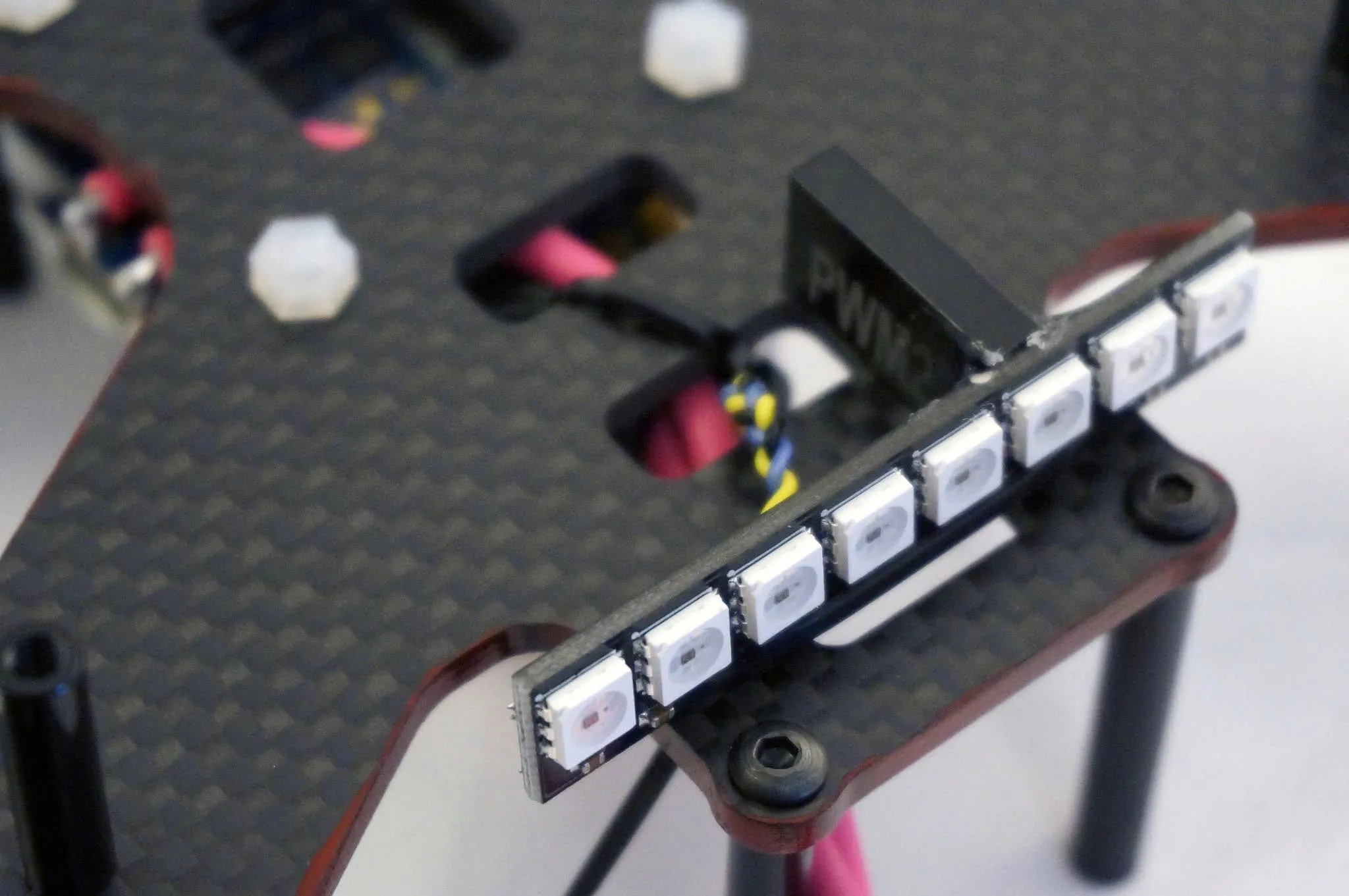
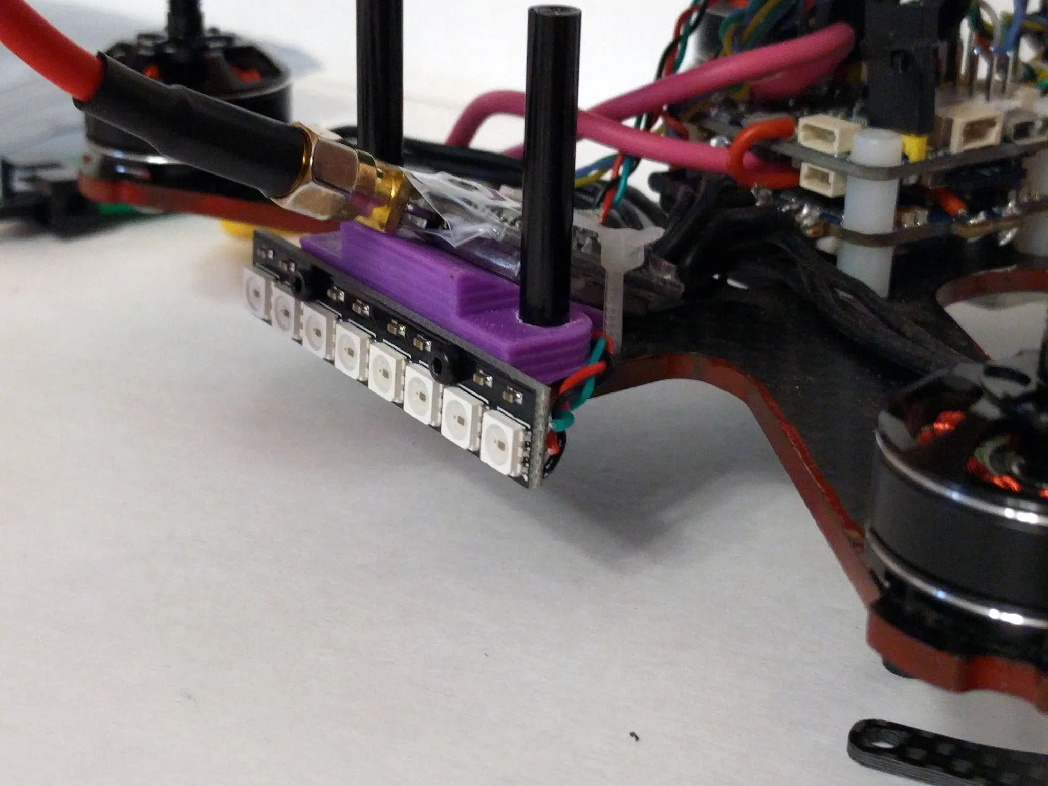
Install the LED strip.
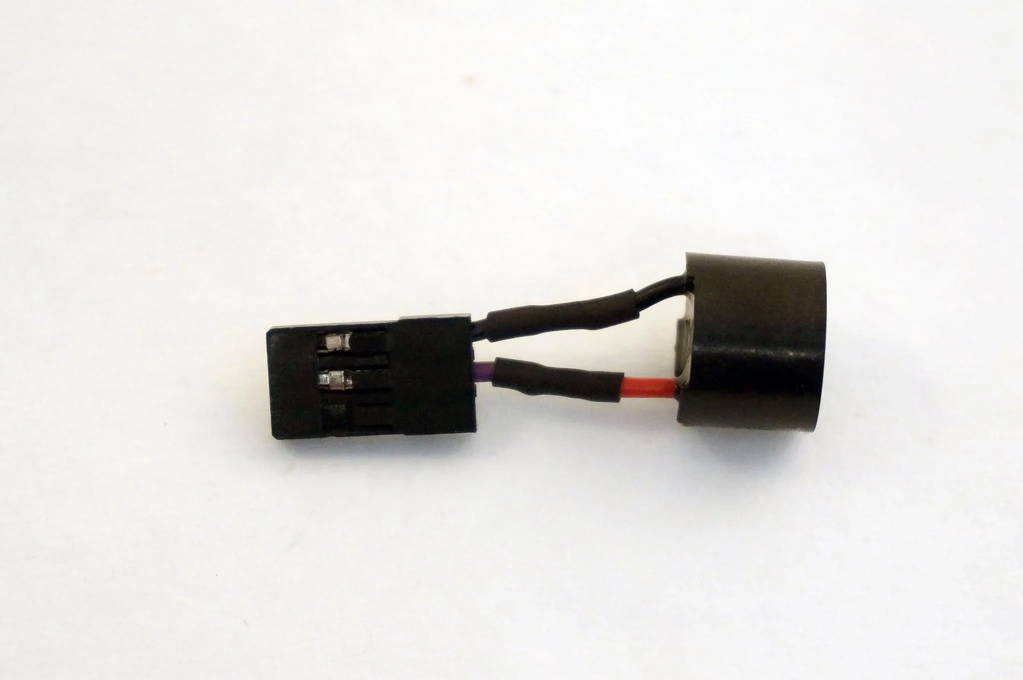
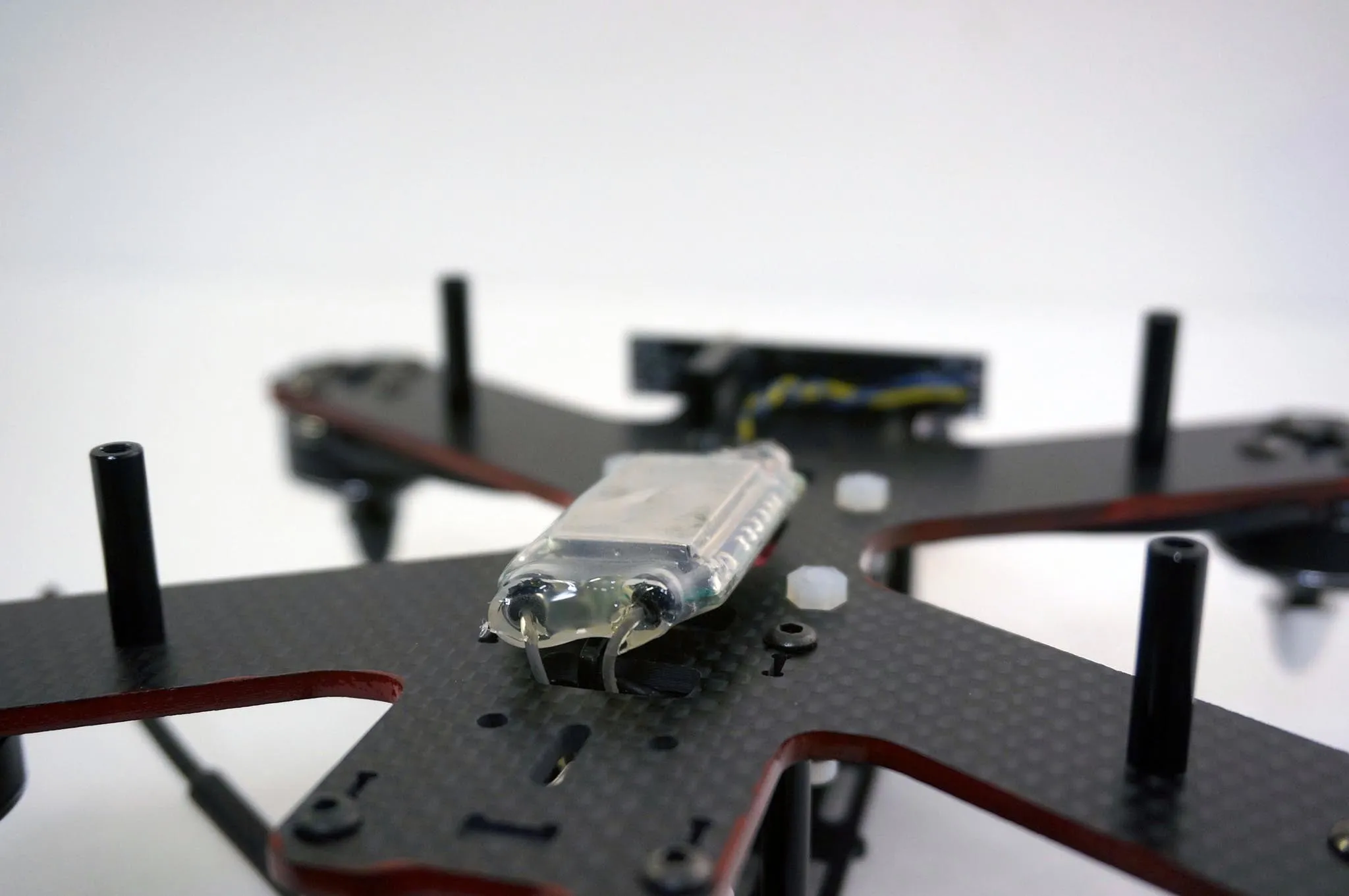
Assemble the beeper.
Install the better.
Video transmitter
I’ll mount the transmitter here. I used a dab of hot glue to keep the zip tie in place.
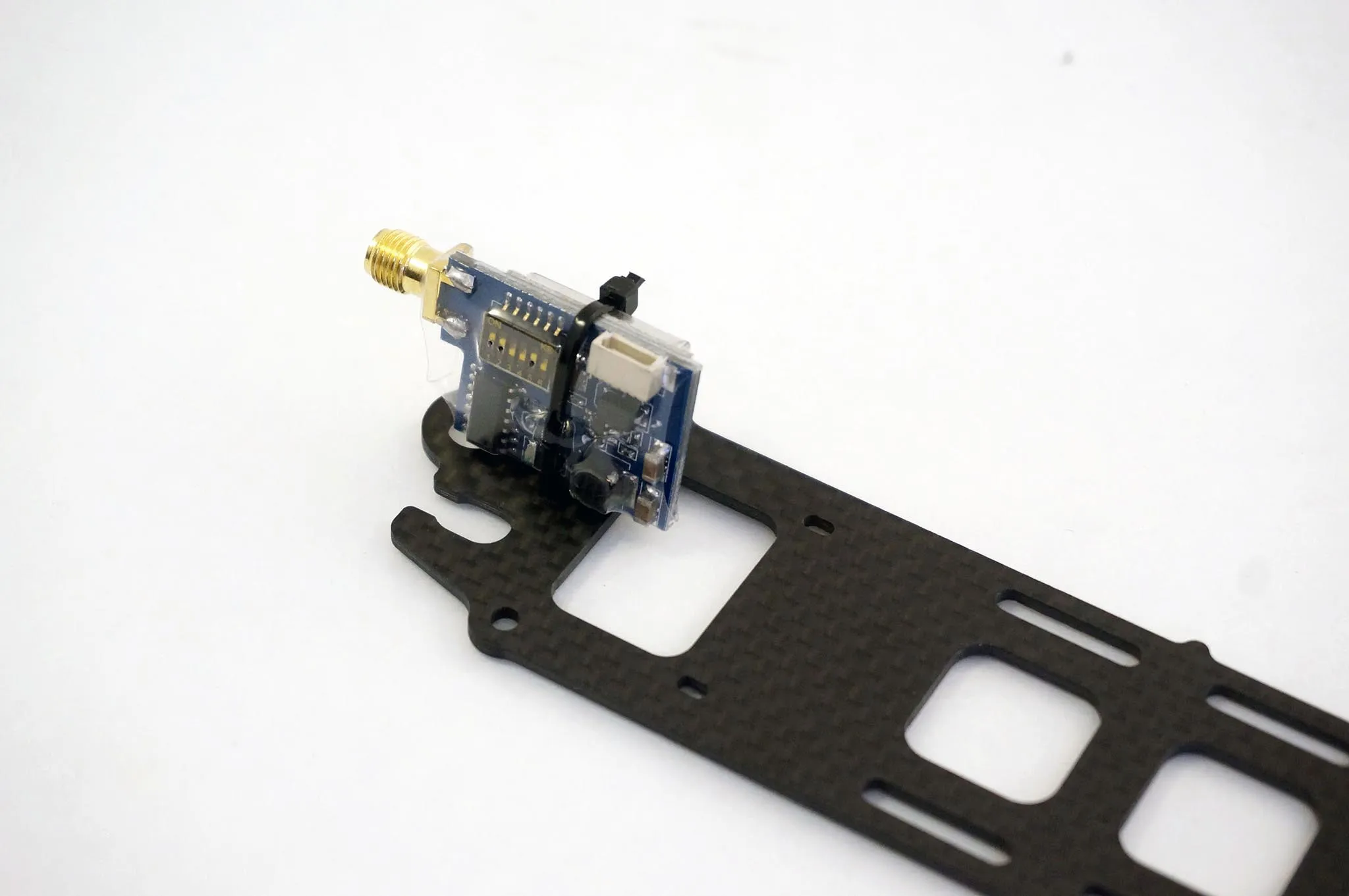
I came back later and
Download the part on thingiverse: /downloads/this-part
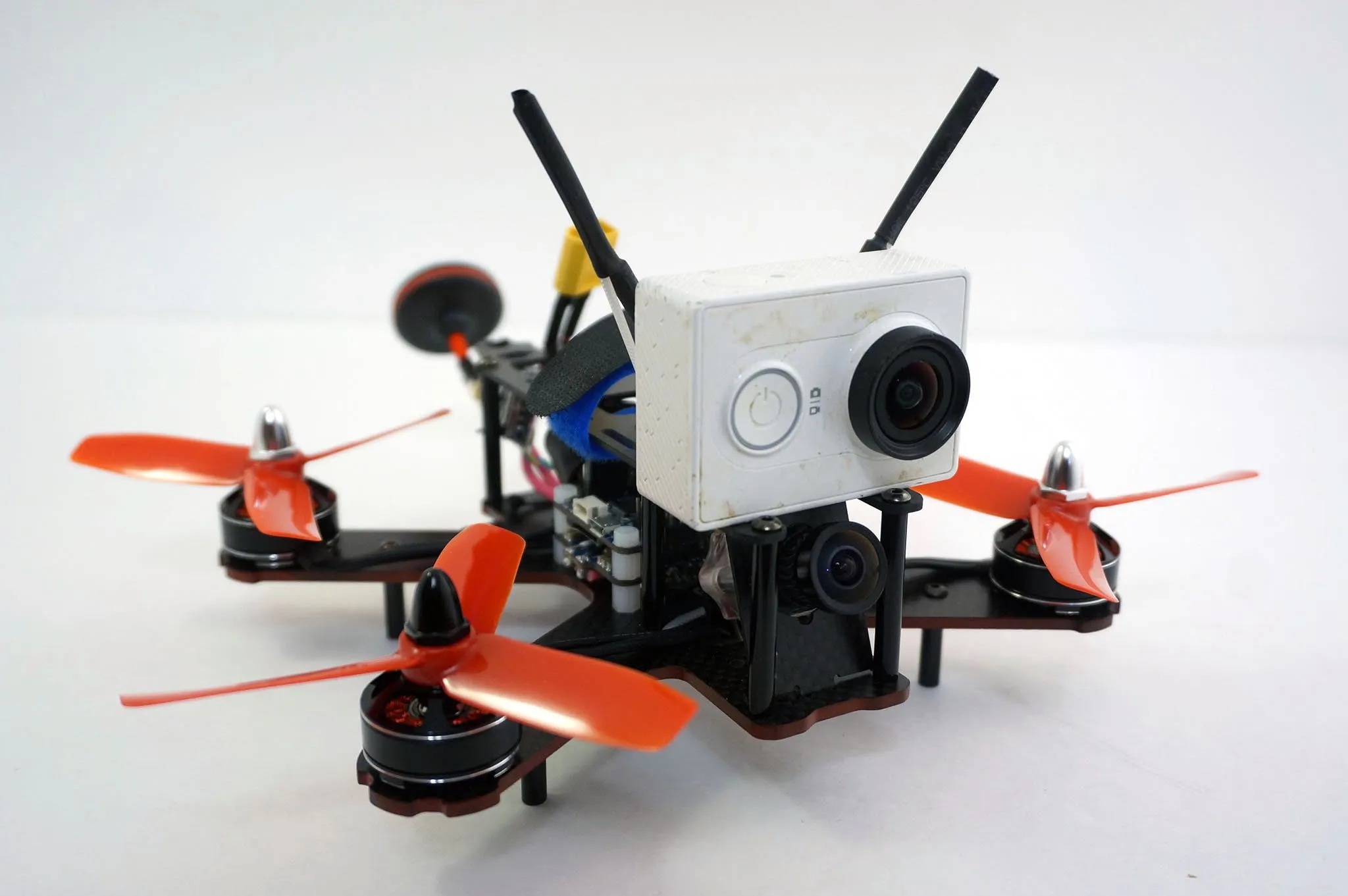
Screw the camera into the faceplate.
Mount the camera.
Install the top plate.
Looking good.
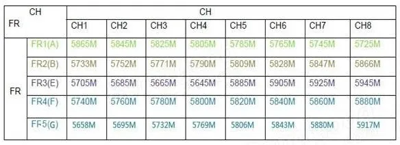
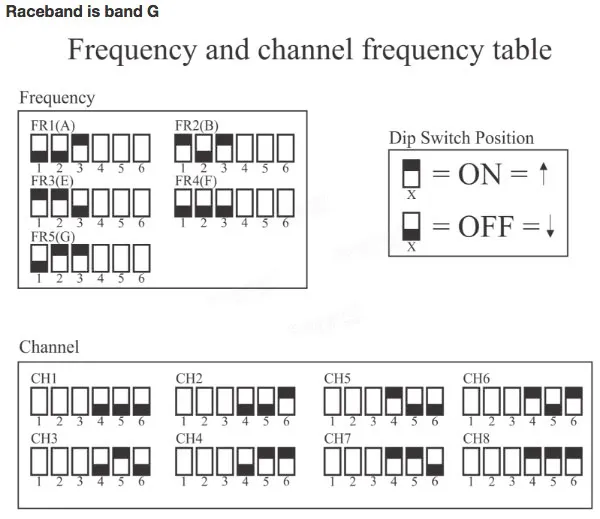
Channels
Dip Switch
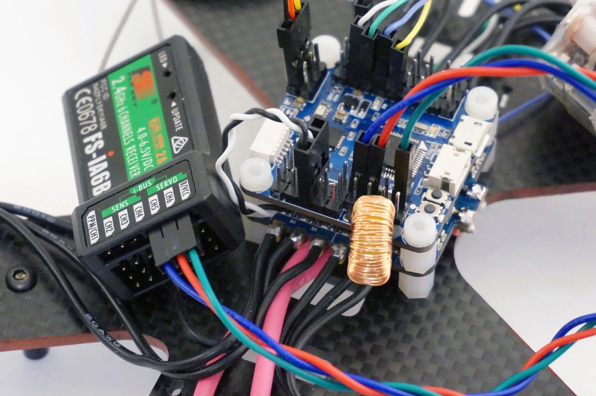
Receiver
We’ll be using the FlySky iA6B Receiver included with the FlySky i6 Radio Transmitter. The protocol is IBUS and we’ll use Serial Port 2. If you’re using other serial devices, you can choose any open serial port.
Update Aug, 2016: The shared PPM / SERIAL RX pin is working so there is no need to use UART2. Simply plug into this port and configure the receiver for UART3 as described below.
Wire it up like so, I’m using UART2:
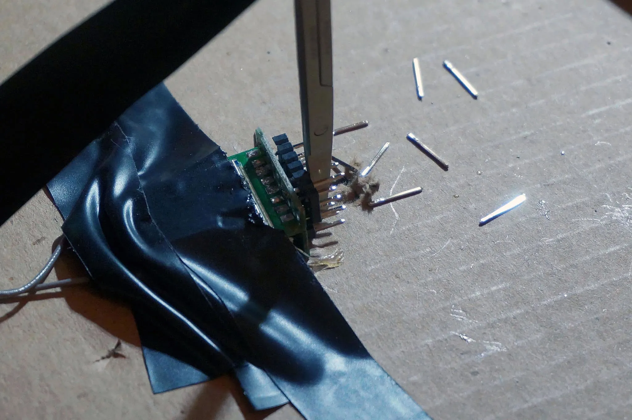
I also removed the case and pins.
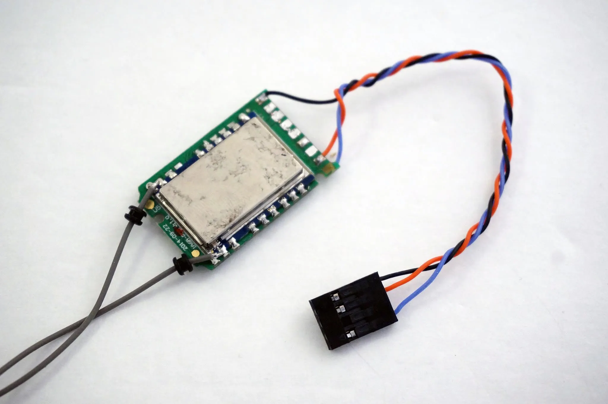
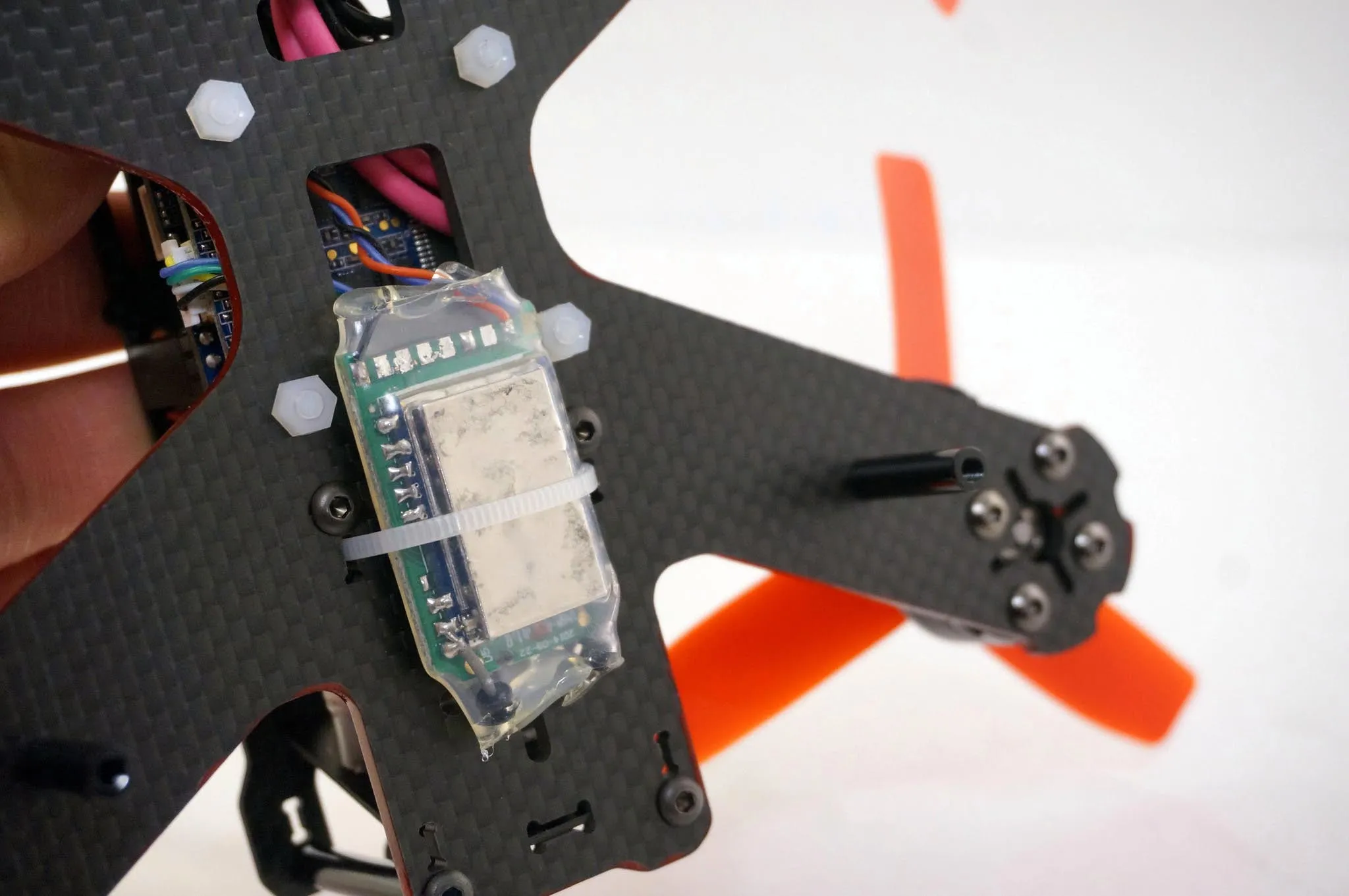
I highly suggest you also wire the BIND pin to a jumper, so you can re-bind it at will. It’s the white wire in this photo:
Here are the pinouts for those interested:
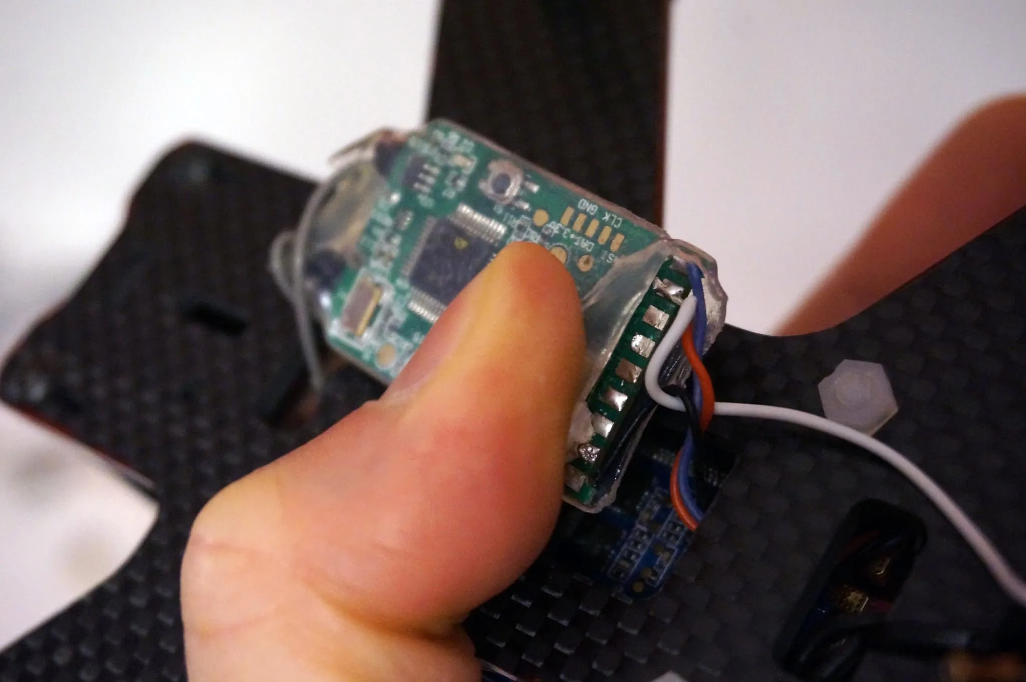
Then mounted it on the bottom of the quad.
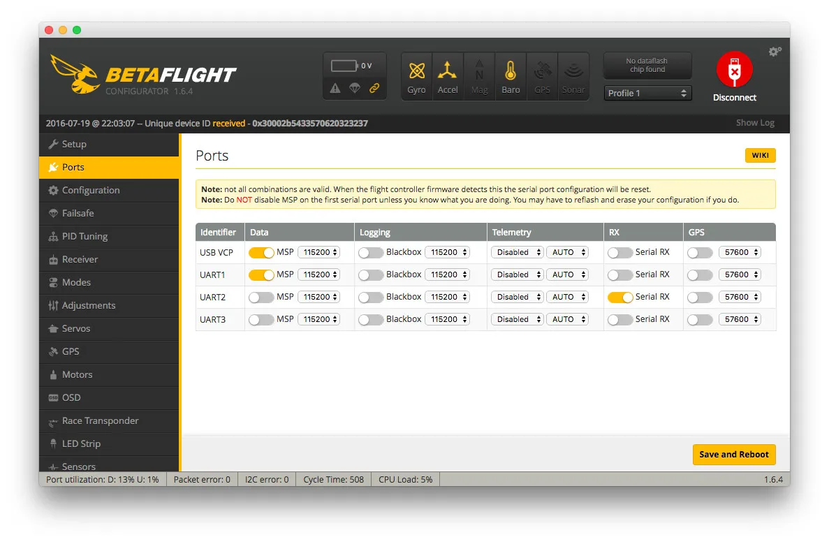
So first, go to the ports tab and enable Serial RX for UART2.
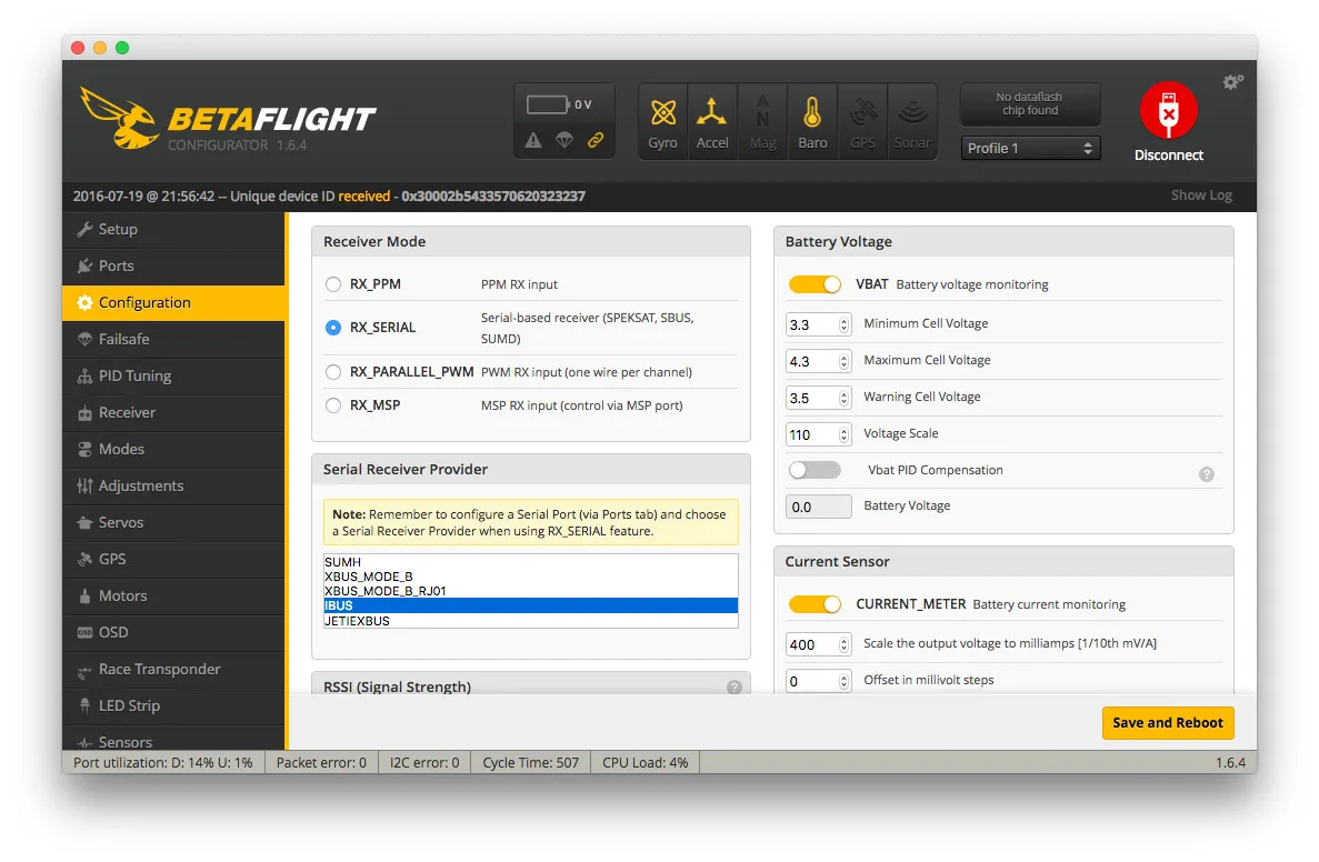
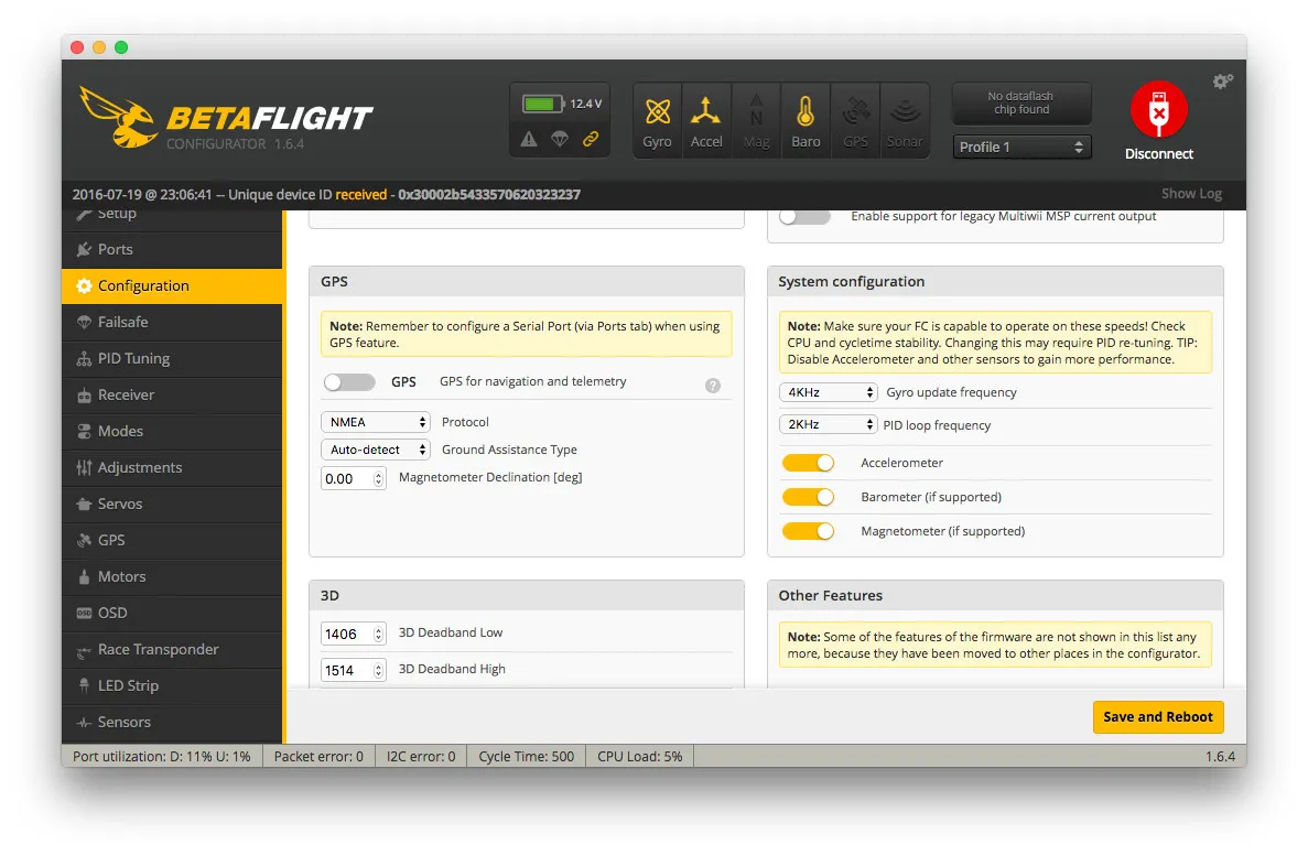
Then open the configuration tab and pick RX_SERIAL under the Receiver Mode section and IBUS for the Serial Receiver Provider.
Now would be a good time to set your flight modes and switches. First, let’s setup the radio.
Flysky FS-i6 Transmitter Config
Start by configuration your transmitter to send the proper switches on the given channels.
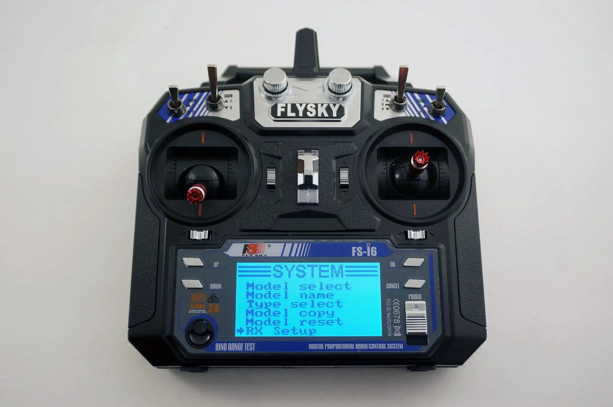
Press and hold OK on the transmitter to bring up the menu.
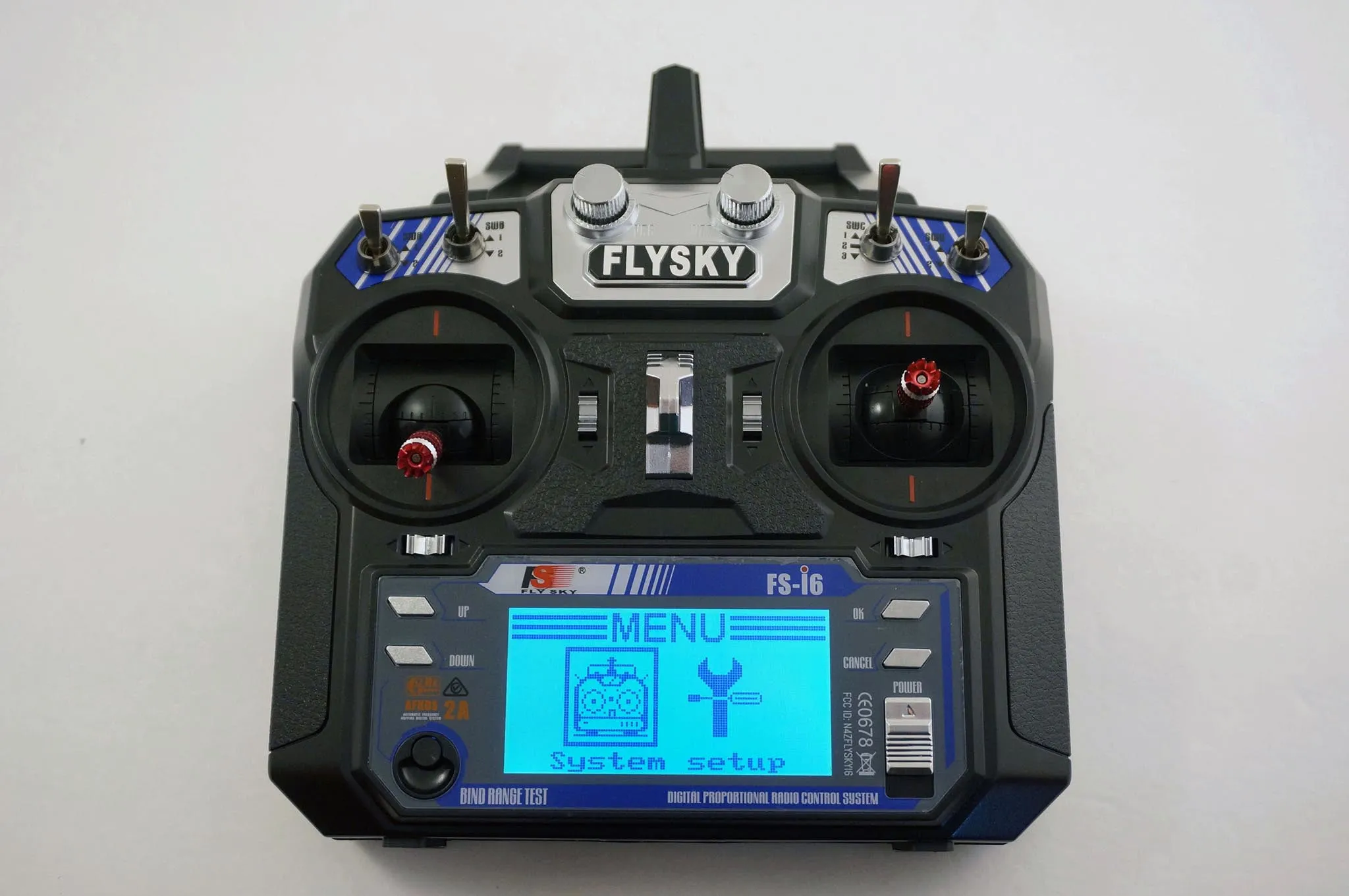
Hit UP to move the cursor to Functions Setup and hit OK
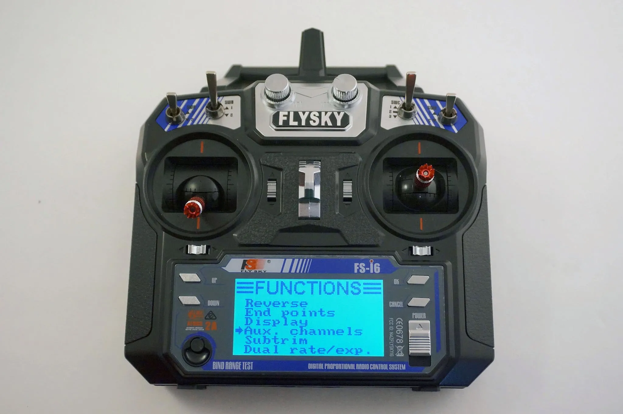
Move DOWN until you get to AUX Channels then hit OK
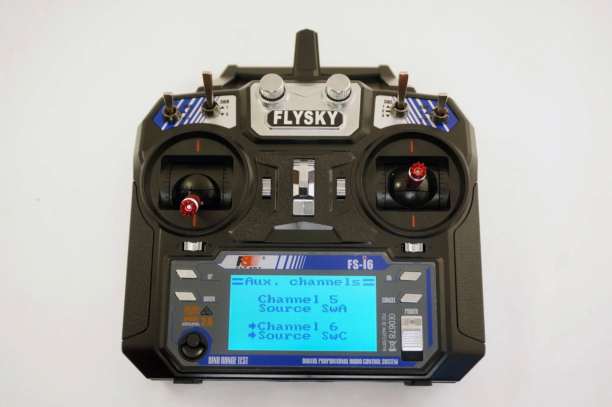
Hit UP to change channel 5 to SWA hit OK and change channel 6 to SWC
Press and hold Cancel to save and get out of the menu, then press Cancel twice more to exit the menus.
Check the receiver tab in the configurator and make sure moving the switches moves AUX1 (far left switch) and AUX2 (3 position switch).
Then go setup your modes.
We’ll use the left most switch to arm and the 3 position switch for flight modes.
Acro mode by default, then middle will be for horizon (which is auto-leveling but still allows flips) and all the way down will be angle (which doesn’t allow flips) and beeper. The beeper is enabled with Angle mode in case I lose video, I can take off my goggles and look for the quad while listening for the beeper.
Paste this into the configurator or set them on the modes tab:
aux 0 0 0 1700 2100
aux 1 1 1 1800 2100
aux 2 2 1 1300 1700
aux 3 12 1 1800 2100
Before you go fly, you must configure your fail safe.
The way to do this on the FS-i6 is as follows.
Press and hold OK on the transmitter to bring up the menu.
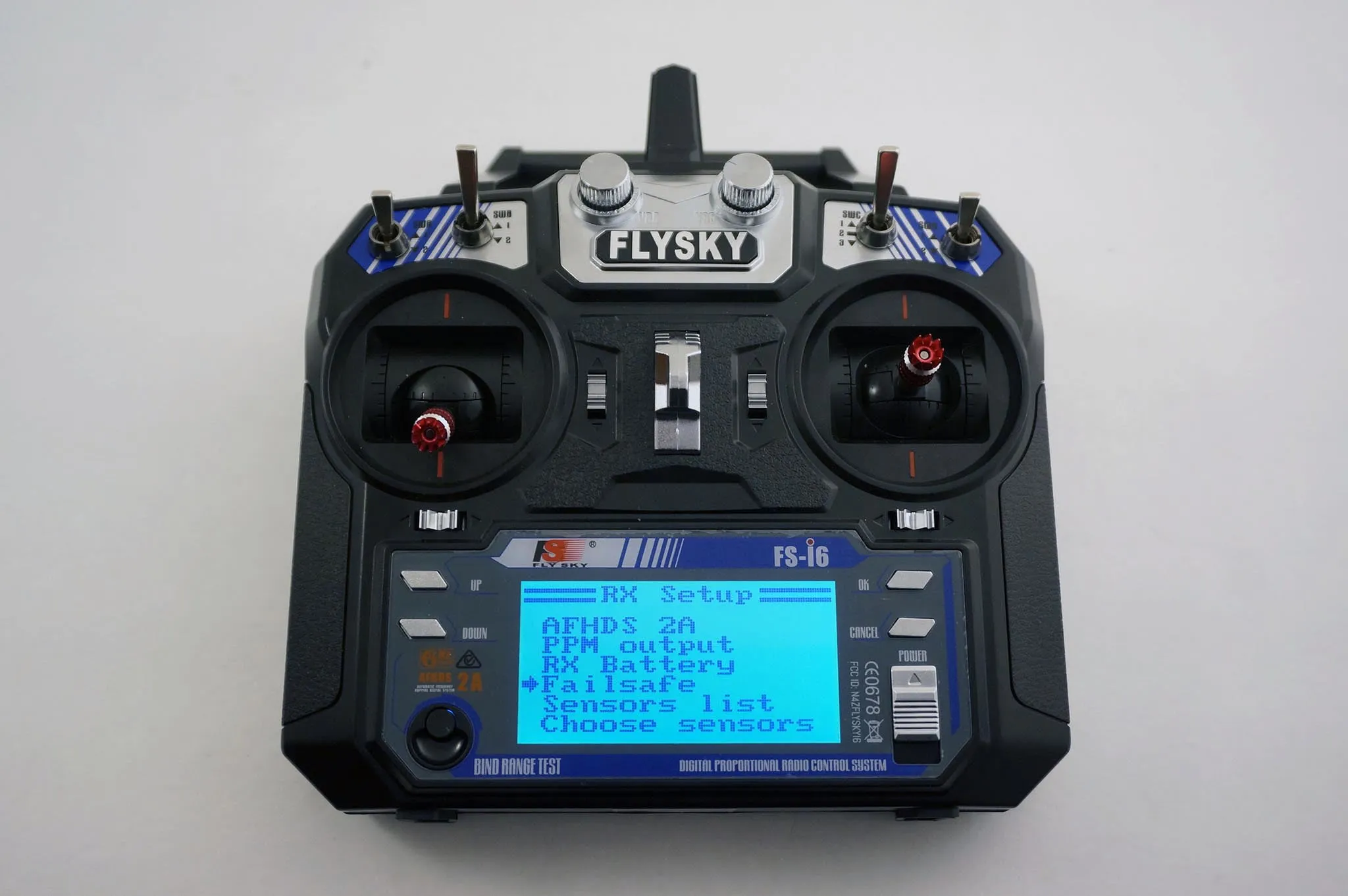
Go to the RX menu
Open to the failsafe settings page.
Go to channel 1 and turn it on, this may seem counter intuitive, but by leaving all the channels OFF this actually makes the receiver hold last position. By turning on the first channel, it will go below the lowest allowable value when a fail safe occurs and BetaFlight will go into failsafe mode.
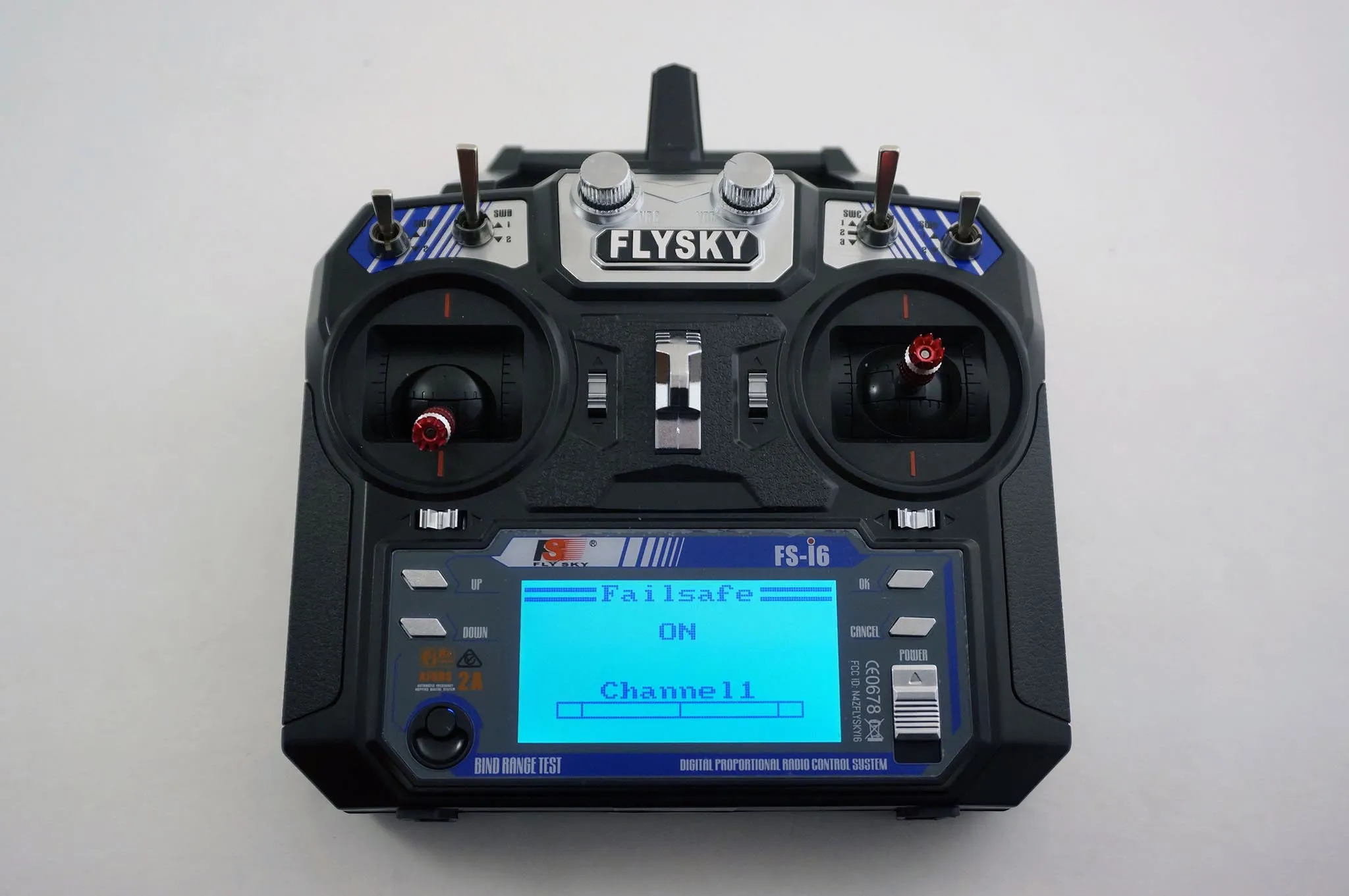
Be sure to hit OK then press and hold cancel to save.
Test the fail safe before flying, without props!
I also like to turn down the fail safe timeout. The receiver timeout takes a few seconds to timeout, so I turned down the flight controller failsafe delay almost all the way:
set failsafe_delay = 2
set failsafe_off_delay = 2
If you’re using PPM mode. The setup is almost the same, just connect like so and enable RX_PPM instead of Serial RX. Here is an example with the same FlySky iA6B Receiver, which can also do PPM.
Blackbox
To get the blackbox working, simply insert a FAT32 formatted micro SDcard. Make sure the partition is set to be Master Boot Record (MBR).
If you’re using a mac, plug in the SDcard, open a terminal and run:
› diskutil list
/dev/disk0 (internal, physical):
   #:                       TYPE NAME                    SIZE       IDENTIFIER
   0:      GUID_partition_scheme                        *1.0 TB     disk0
   1:                        EFI EFI                     209.7 MB   disk0s1
   2:          Apple_CoreStorage meta                    1.0 TB     disk0s2
   3:                 Apple_Boot Recovery HD             650.0 MB   disk0s3
/dev/disk1 (internal, physical):
   #:                       TYPE NAME                    SIZE       IDENTIFIER
   0:      GUID_partition_scheme                        *2.0 TB     disk1
   1:                        EFI EFI                     209.7 MB   disk1s1
   2:                  Apple_HFS data                    2.0 TB     disk1s2
/dev/disk2 (internal, virtual):
   #:                       TYPE NAME                    SIZE       IDENTIFIER
   0:                  Apple_HFS meta                   +1.0 TB     disk2
/dev/disk3 (external, physical):
   #:                       TYPE NAME                    SIZE       IDENTIFIER
   0:      GUID_partition_scheme                        *2.0 GB     disk3
   1:       Microsoft Basic Data UNTITLED                2.0 GB     disk3s1
Find your SDcard device on the list then run, replacing disk3 with the path to your disk:
sudo diskutil eraseDisk FAT32 UNTITLED MBRFormat /dev/disk3The SDCard should be inserted upside down with the pins facing up.
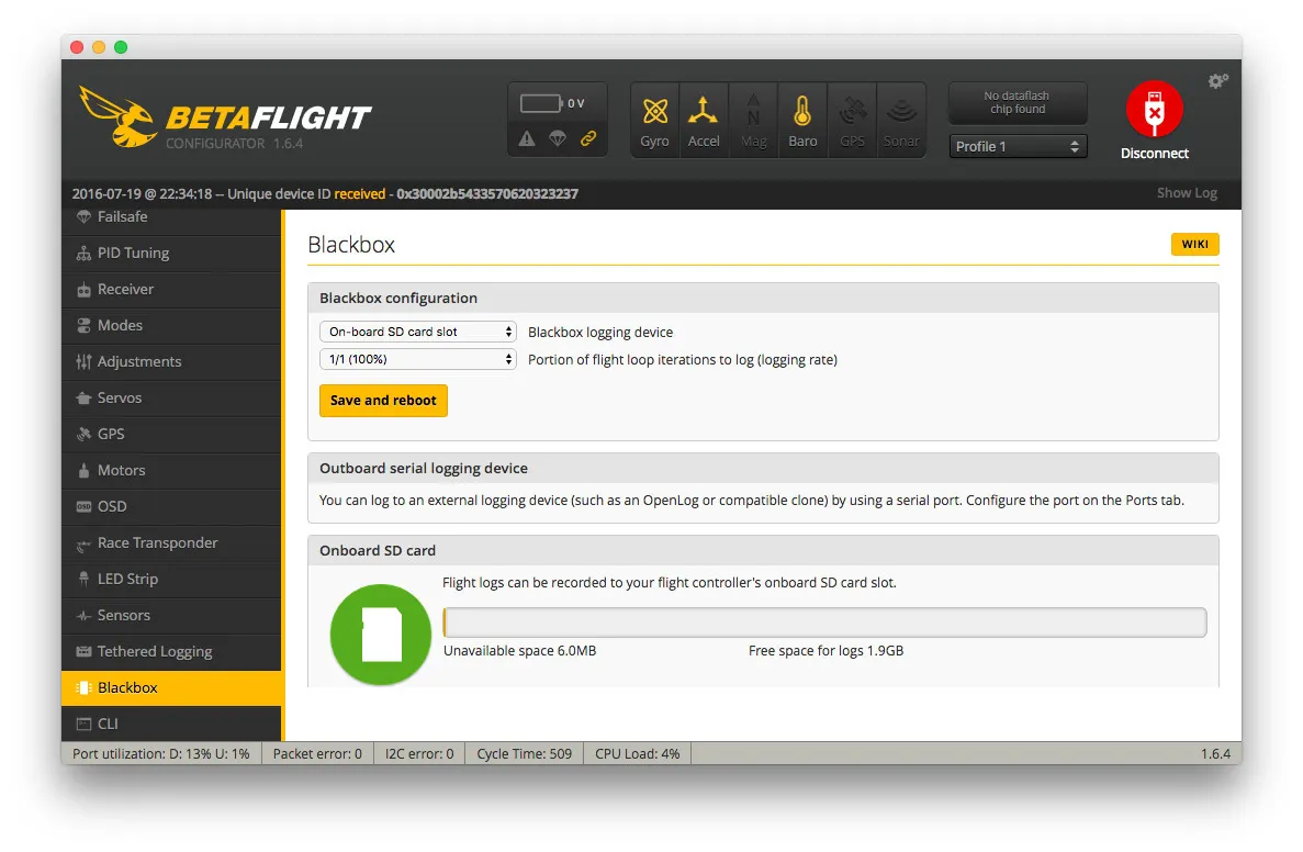
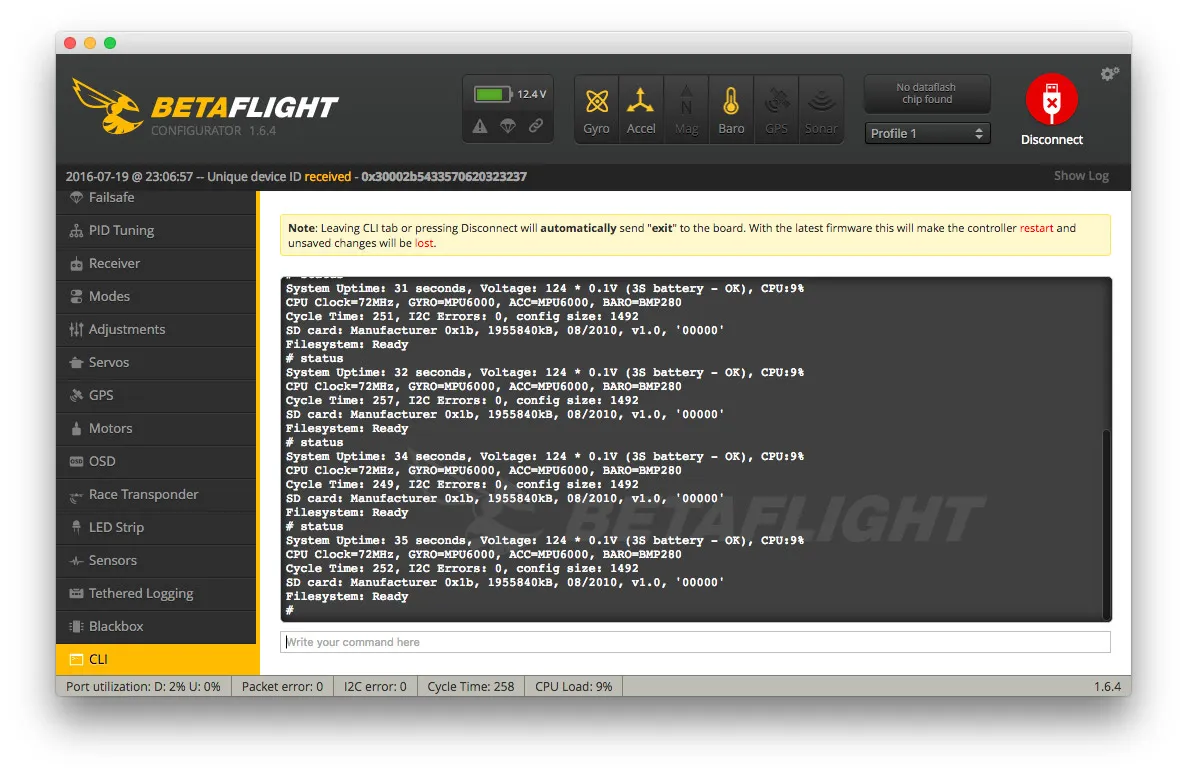
Open the BetaFlight configurator and go to the blackbox tab. You’ll see a message stating all is well!
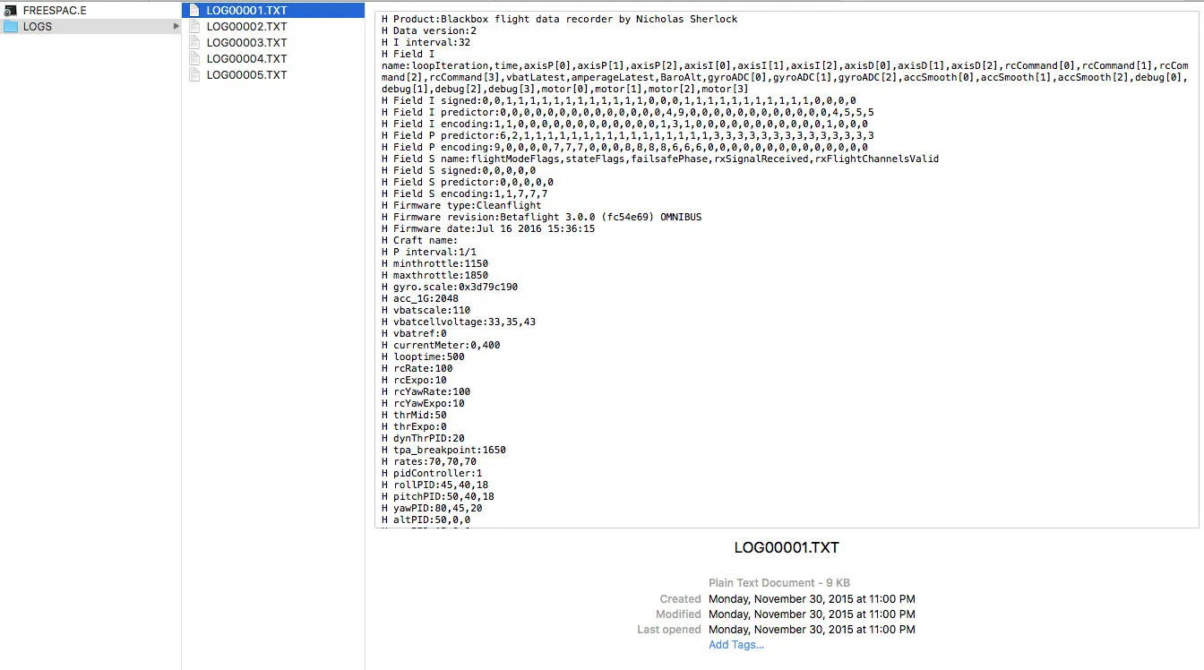
To pull the logs, simply copy them off the SDCard from your computer!
Led Strip
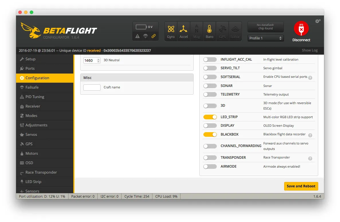
Open the Configuration Tab and under Other Features enable LED_STRIP. Note that the TRANSPONDER cannot be enabled at the same time. You can use either the led strip or the transponder.
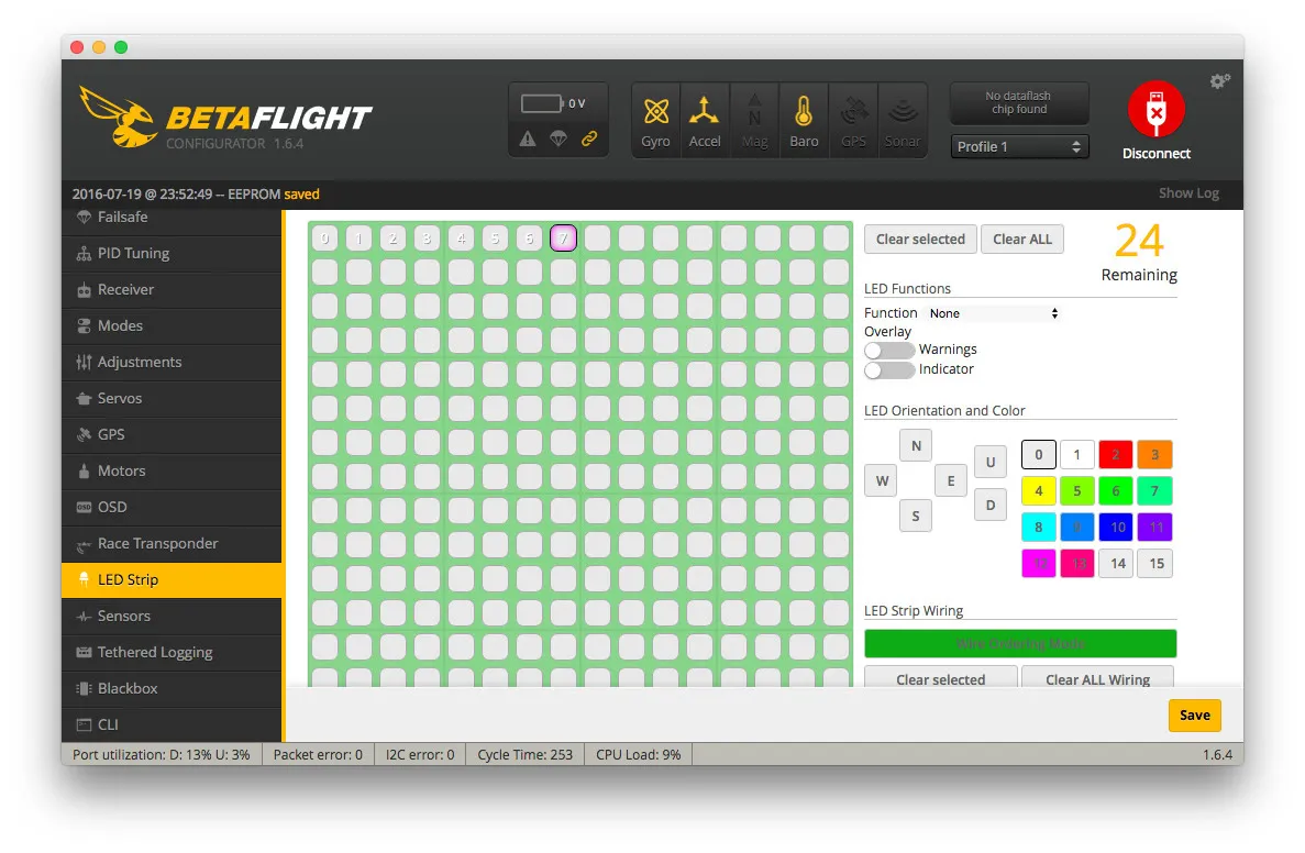
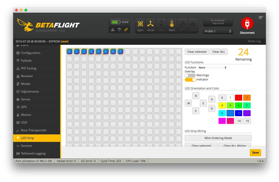
Start by setting the LED order. Hit Clear All, then Wire Ordering Mode then click 8 boxes in a row (or however many LEDs you have in whatever configuration) and click Wire Ordering Mode again to exit ordering mode.
My config is pretty simple, colored leds with throttle indication in the middle.
Other configuration
Download my BetaFlight 3.0 config here or use the following settings:
- 4khz (250ms loop time). Because it’s awesome!
- Adjust min check and max check
set min_check = 1040
set max_check = 1900- Super Expo and Airmode
feature AIRMODE
feature SUPEREXPO_RATES
Troubleshooting
Quad won’t arm
Give it a few seconds after you plug in the battery, sometimes the SDCard takes a second or two to settle. If you still can’t arm after waiting more than 30 seconds. Open the configurator and run status several times. Copy the output and ask for help on the forums (or leave a comment below). You won’t be able to arm if the CPU usage is too high.