Mostly Printed CNC (MPCNC)
This is my build log of Vicious1’s Mostly Printed CNC.
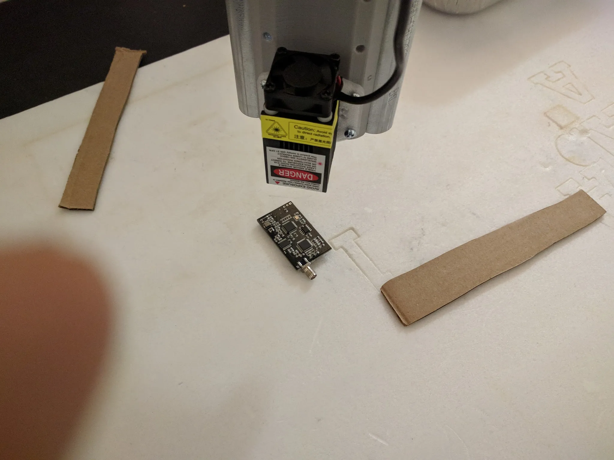
Here we are running a 2.5W diode laser on it.
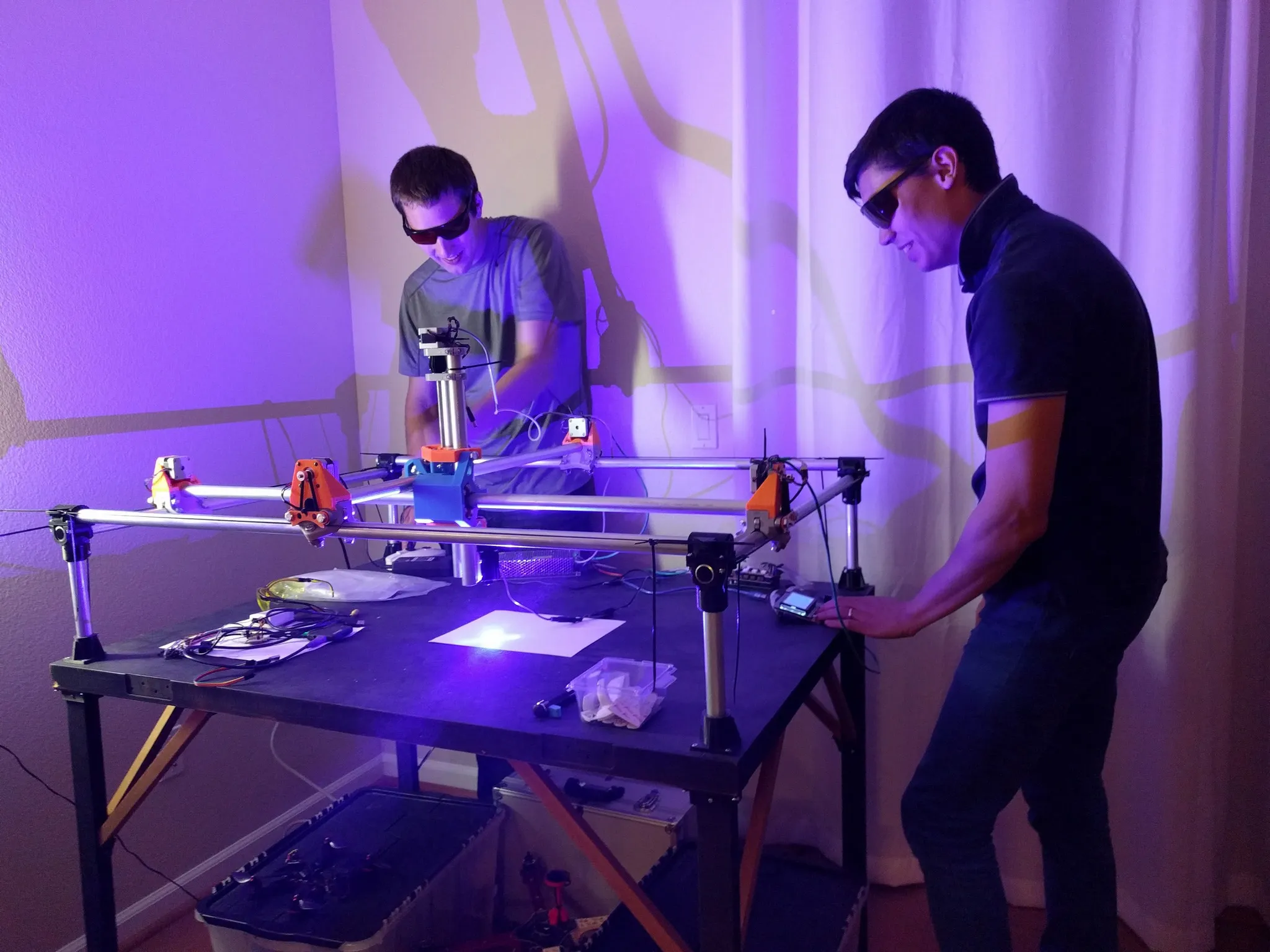
Huge shout out to Tim, in the photo above, for helping me get past the final hurdles of this project. He hand-wrote some g-code to get this working before we found a tool to generate it.
Parts
The awesome thing about this CNC is that it can be built using only parts made on your
Hardware
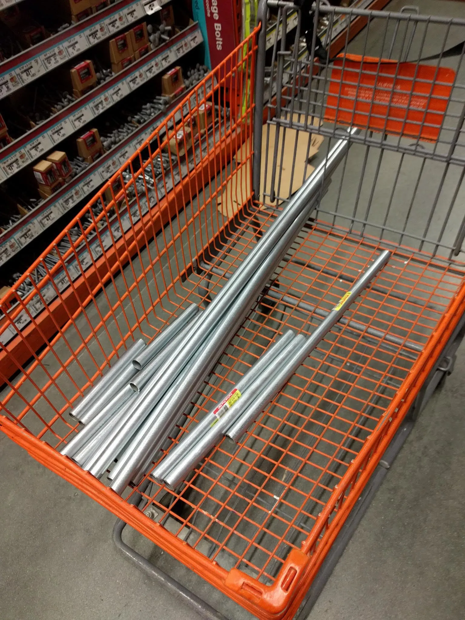
My build started with a trip to Home Depot where I bought conduit. If you choose your dimensions before you start, you’ll even be able to get the conduit cut at the store for free.
If you want to copy my build exactly, here are the dimensions I used (all units are in inches). I sized mine to fit on an extra door I had lying around. I used this door as the cutting table.
| Hardware | total length(in) | qty | total(in) | size(in) | plus(in) | |
|---|---|---|---|---|---|---|
| Conduit | x-axis | 139.2 | 3 | 46.4 | 36 | 10.4 |
| y-axis | 103.2 | 3 | 34.4 | 24 | 10.4 | |
| z-axis | 31 | 2 | 15.5 | 8 | 7.5 | |
| legs | 46 | 4 | 11.5 | 12 | -0.5 | |
| total: | 26.62 | ft | ||||
| GT2 | x-axis | 106.8 | 2 | 53.4 | 46.4 | 7 |
| y-axis | 82.8 | 2 | 41.4 | 34.4 | 7 | |
| total: | 189.6 | in | ||||
| Rod | 5/16-18 threaded rod | 14 | 1 | 14 | 8 | 6 |
| 7/16 threaded rod | 64 | 4 | 16 | 12 | 4 |
If you want to build a different size table, this awesome calculator will help you figure out how long to cut each piece: http://stevecd.github.io/mpcnc_calc_react/#/?_k=gj9fxl
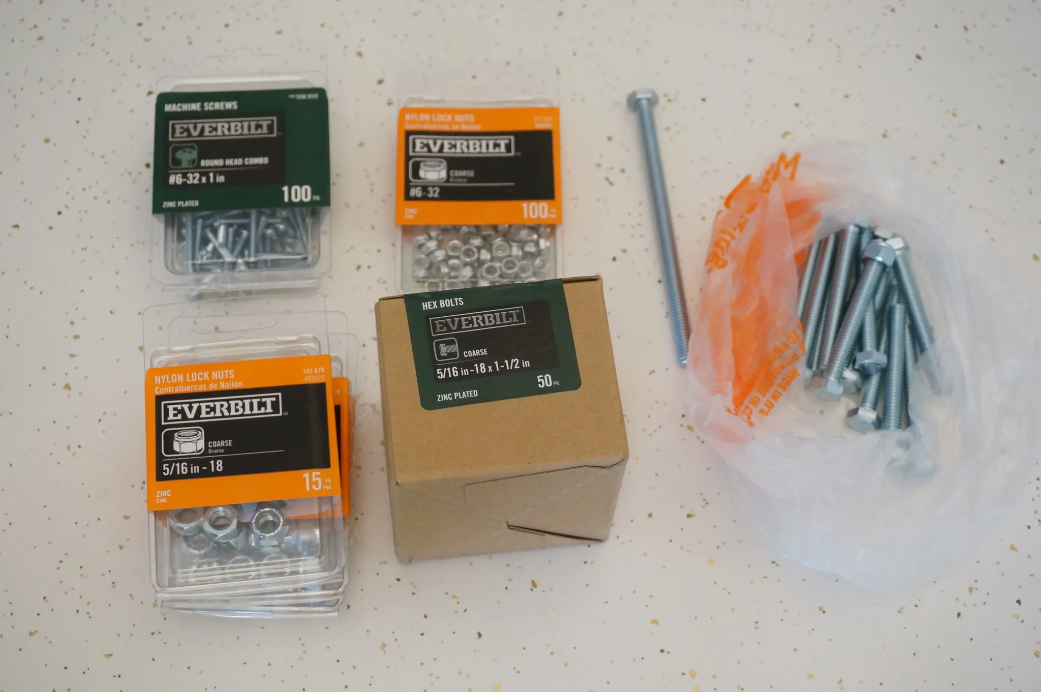
I also picked up the necessary bolts and nuts. I’m building the US/English version; the metric version will be slightly different.
All sizes are in inches unless noted otherwise.
| qty | size |
|---|---|
| 1 | 5/16-18 x 5 |
| 12 | 5/16-18 x 2.5 |
| 2 | 5/16-18 x 1.5 |
| 28 | 5/16-18 x 1.25 |
| 43 | 5/16-18 nylock nut |
| 1 | 5/16-18 x 7/8 coupling nut |
| 19 | M3 x 10mm (ordered from China) |
| 57 | #6-32 x .75 |
| 57 | #6-32 Nylock Nuts |
You’ll also want some wiring. Old Ethernet or phone cable works great for this.
Electronics
I ordered all my electronics from China. It’s cheap and they work great. They took about 3 weeks to arrive, so order these first, as you start printing out all the parts.
| Image | Description |
|---|---|
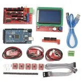 | RAMPS 1.4 Electronics Kit 1x $40 |
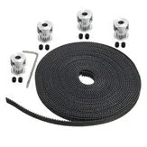 | GT2 timing belt and pulleys 1x $9 |
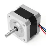 | NEMA 17 Stepper Motors 2.2Kg.cm holding torque 5x $11 |
 | Pack of 100 3mm x 10mm Hex Bolts (to attach the steppers) 1x $5 |
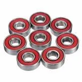 | 10 608 Sealed Bearings 6x $3.85 |
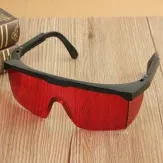 | Laser Glasses 3x $1.80 |
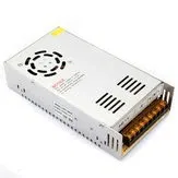 | 12V 30A Power Supply 1x $26 |
You’ll also want some 2.54mm Standard PCB Shunts for the RAMPS.
Even though the included motor drivers work fine and these TMC2100 silent stepper drivers are expensive, if you plan to run your MPCNC in a living space (as I do, with it in my living room) the $40 upgrade is well worth the peace and quiet. The upgraded motor drivers really do make a difference. Check out this comparison: https://youtu.be/ROFYIJ-wOGI?t=10m25s
I ordered a 2.5W diode laser as the primary end effector. It works great. I also ordered a spindle.
| Image | Description |
|---|---|
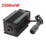 | 2.5W Diode Laser Module 1x $75 |
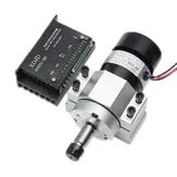 | 400W 12000rpm ER11 Chuck CNC Brushless Spindle Motor and Driver 1x $80 |
Printing
All the printed parts for the US 3/4” conduit version are here on Thingiverse and the metric versions are in the links on that page: 25mm, 25.4mm.
In case you’re curious, US 3/4” has an outer diameter of 23.4mm according to https://steeltubeinstitute.org/steel-conduit/types-of-steel-conduit/electrical-metallic-tubing-emt/.
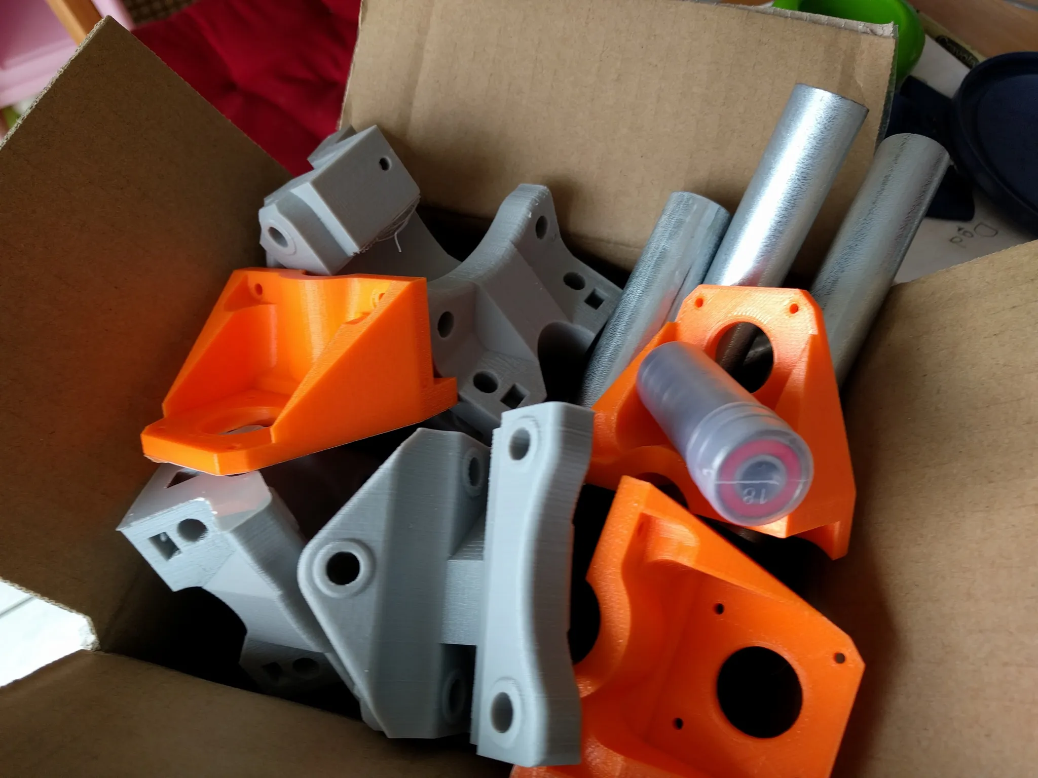
I used ABS to print all the parts. I printed at 253-degree nozzle and a 100-degree heated bed in an enclosed
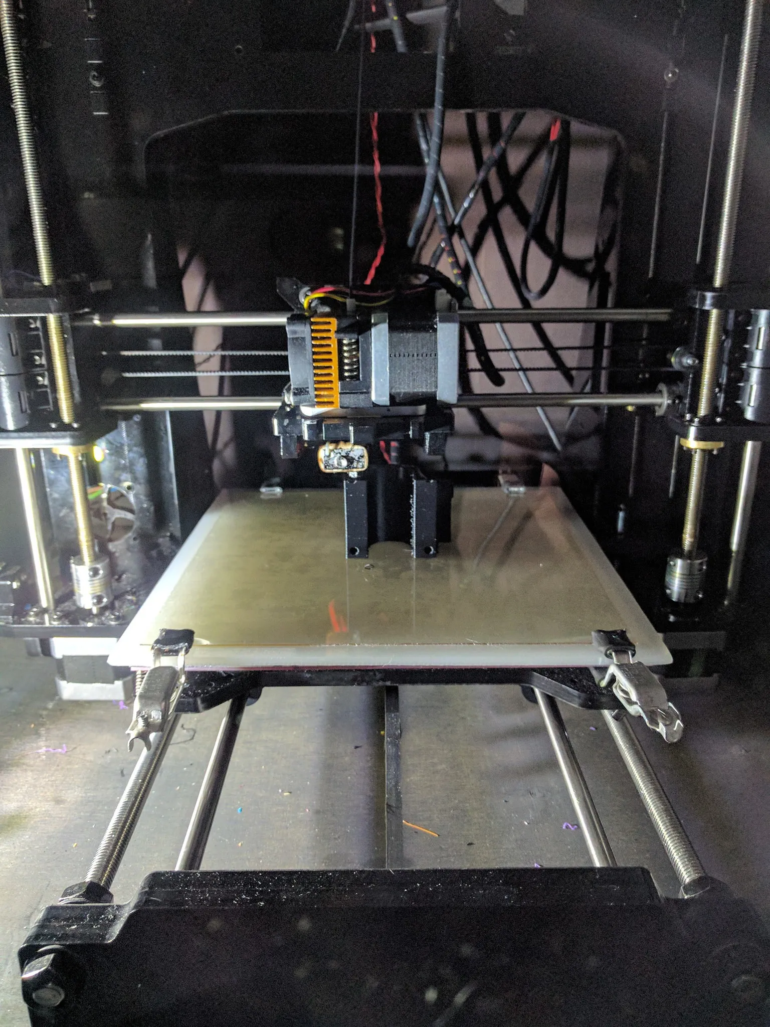
Here’s part of the main carriage.
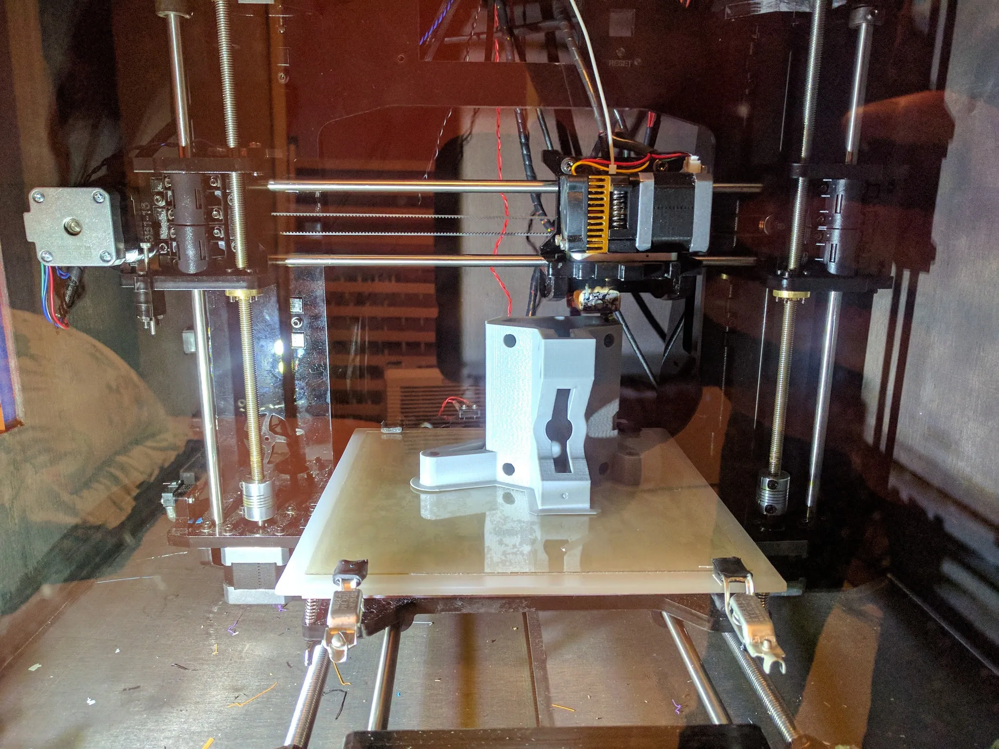
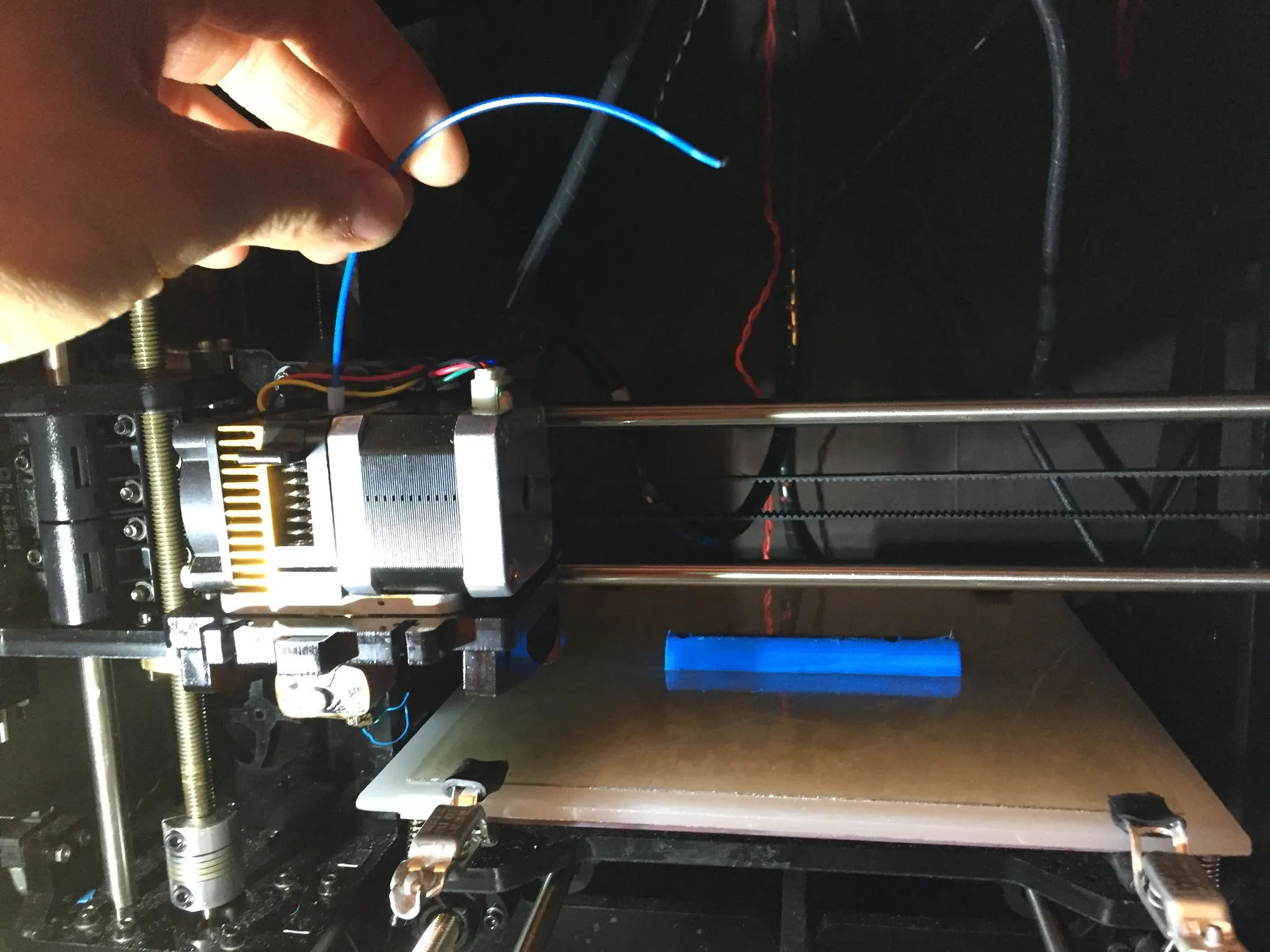
Whew, that was close… almost ran out of filament on this print.
Table
You’ll need a table that fits your CNC. My CNC is pretty big, at 3’ by 4’, so I had to build a custom table.
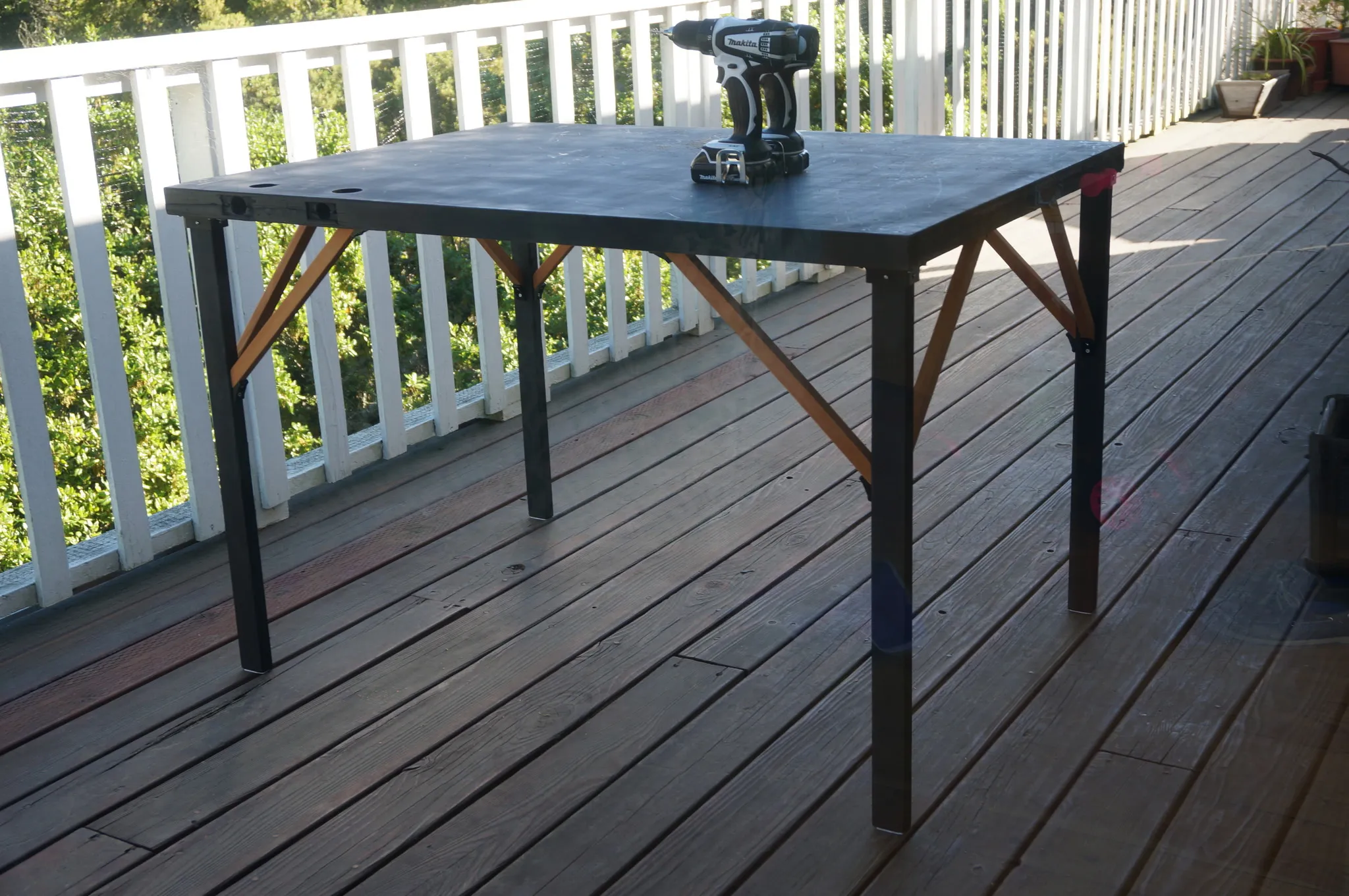
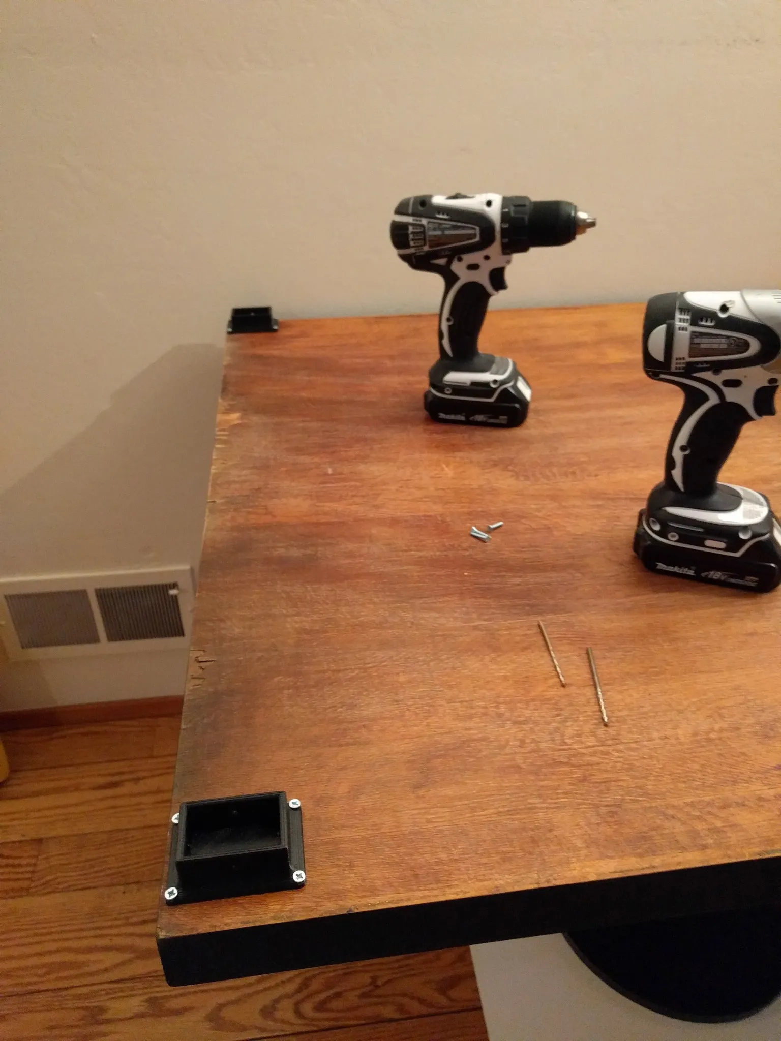
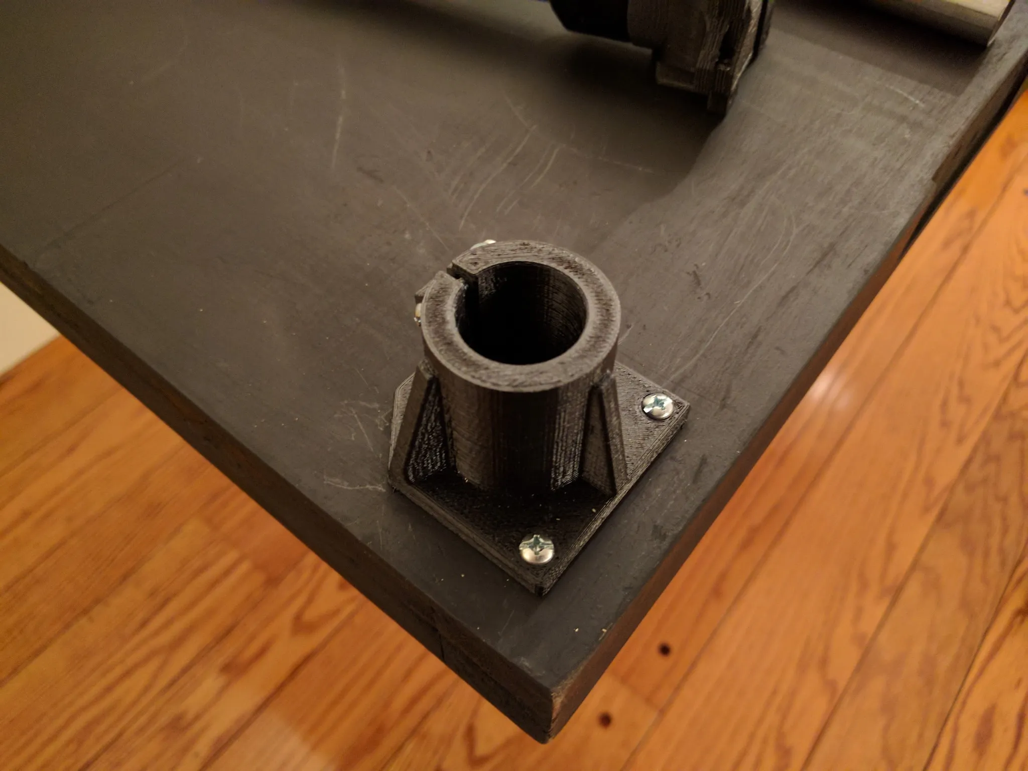
I ended up using an old door I found in the basement and some scrap wood. I printed out these little holders for the legs, but in hindsight, it would have been better to use a more traditional table building method, like a strip of wood lengthwise around the table to which the legs can be bolted.
Then used the 45-degree brackets and a couple more scraps to hold the legs in place.
Build
The build is pretty straightforward and Vicious1 has a good guide on his site over here: https://www.vicious1.com/assembly/
My step-by-step guide follows.
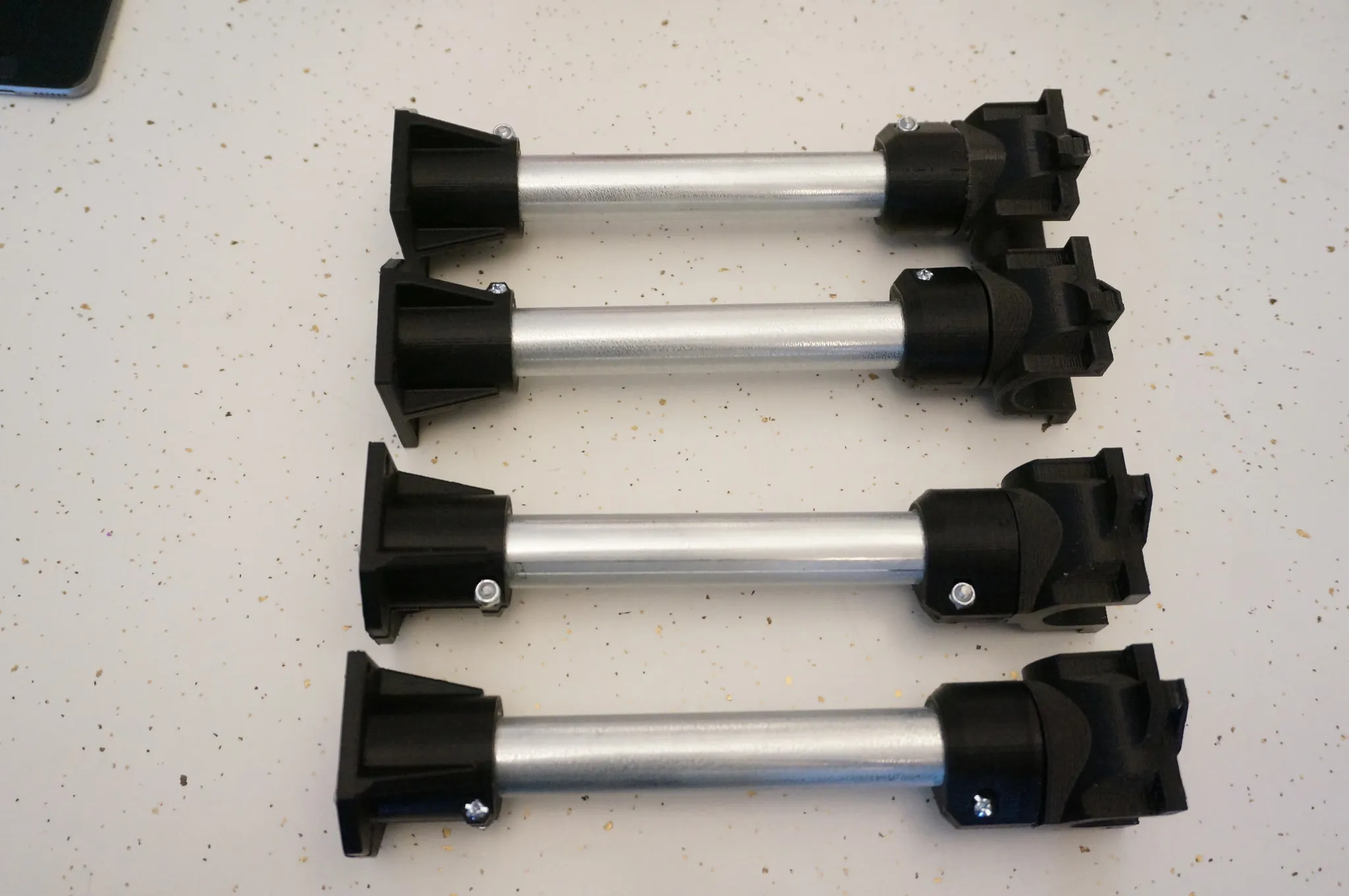
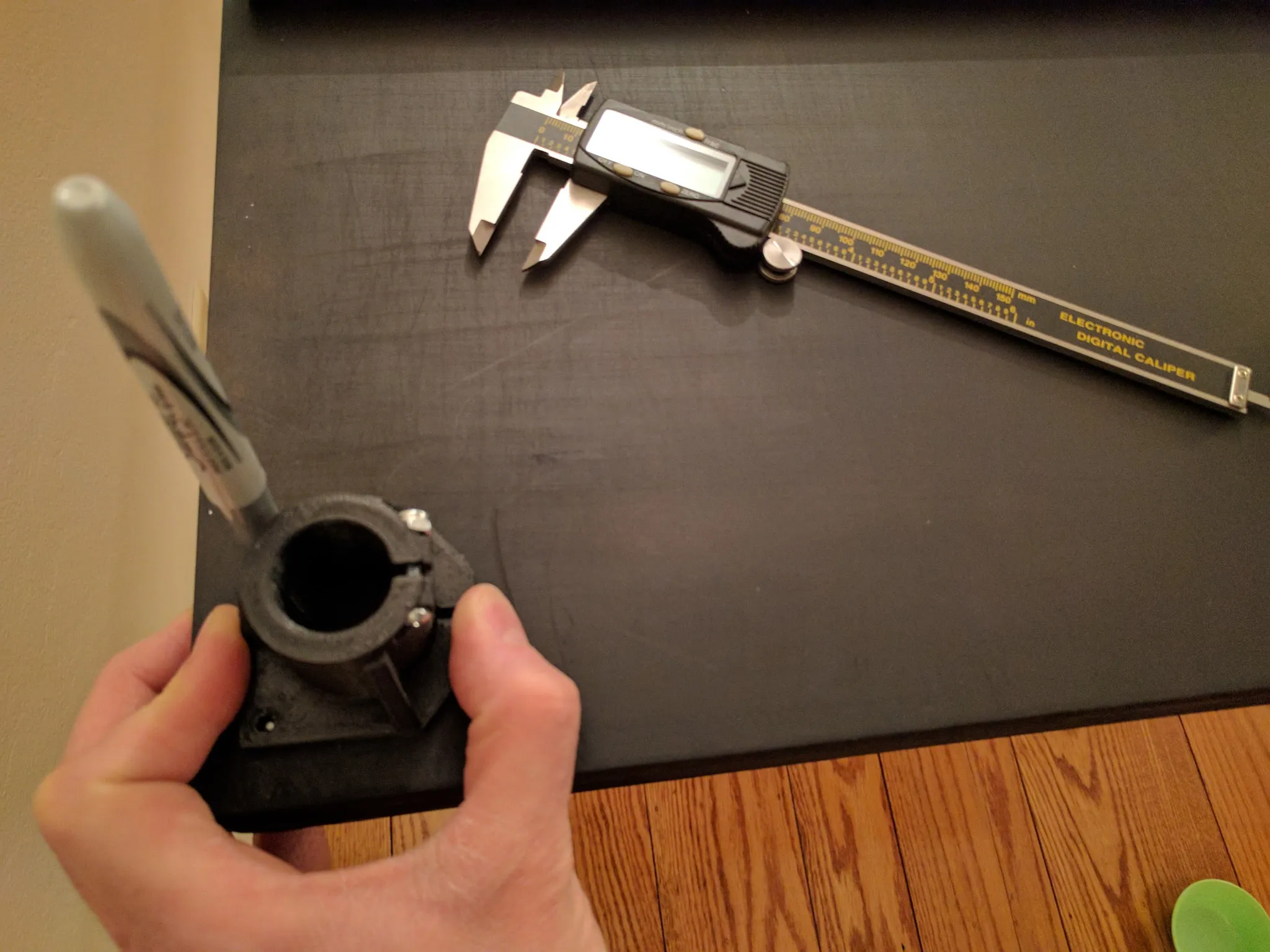
Legs
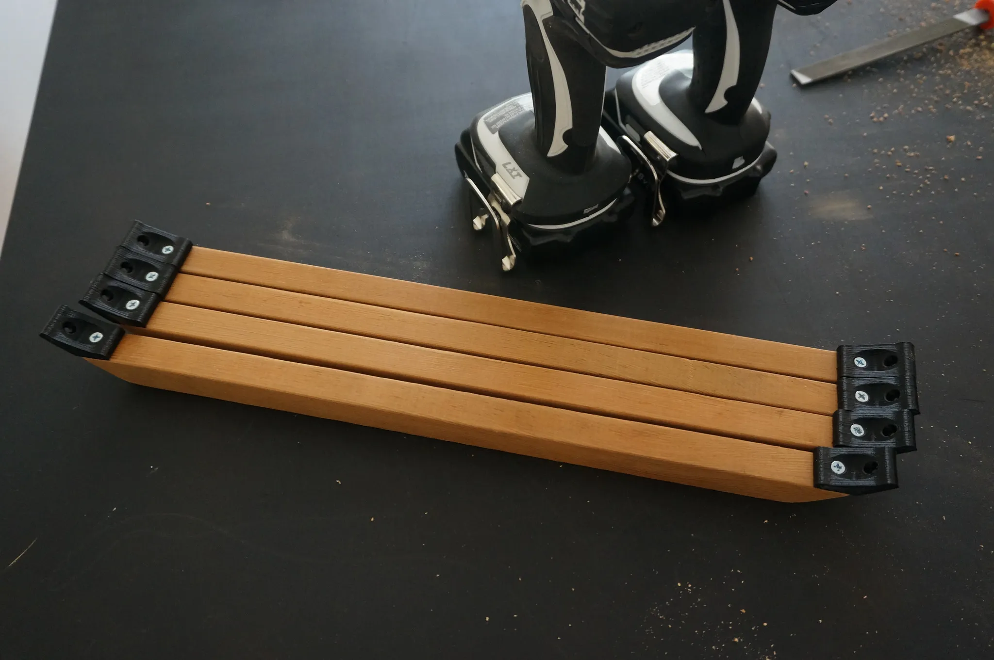
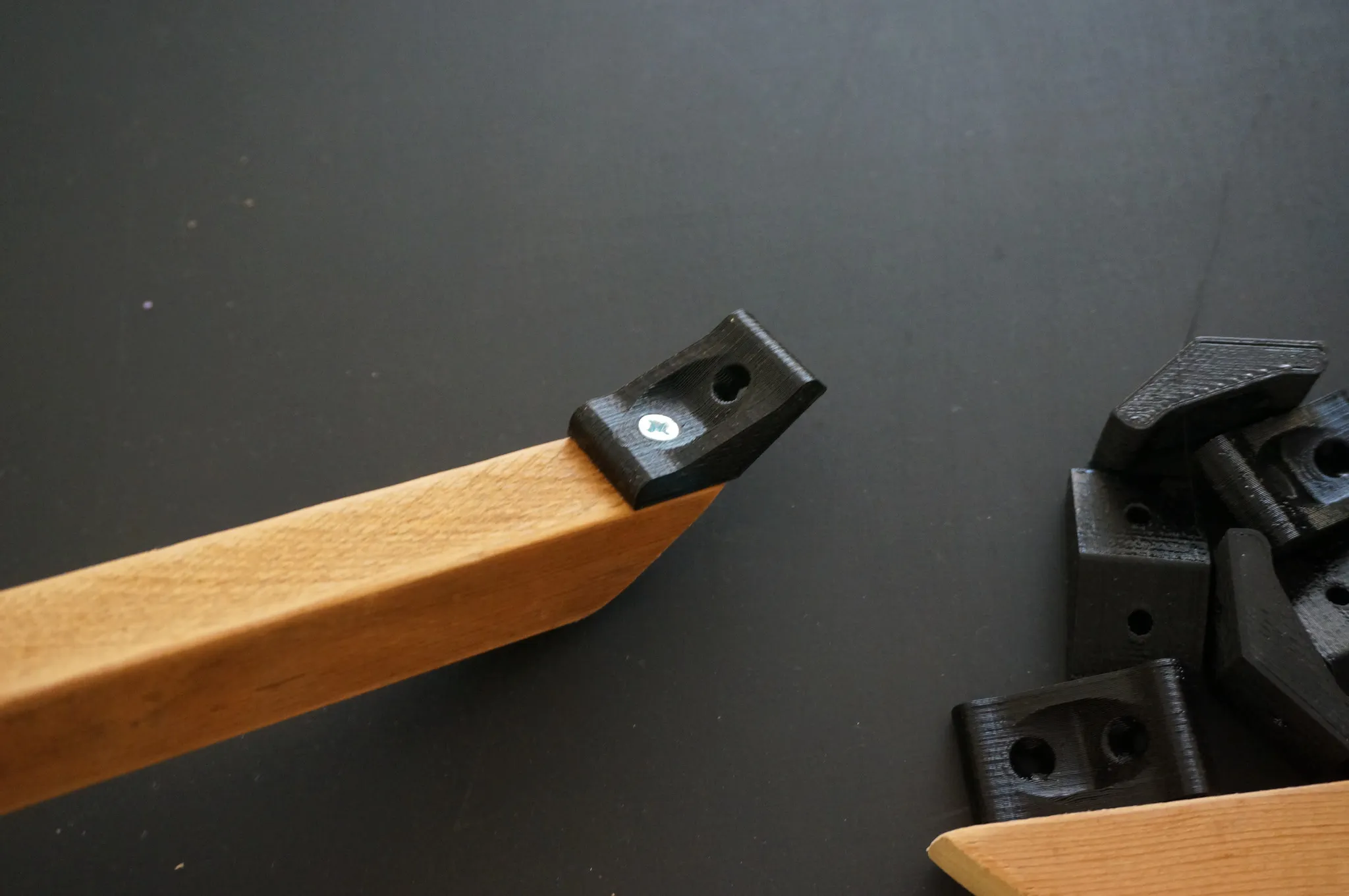
Gather the parts for the tops of the legs.
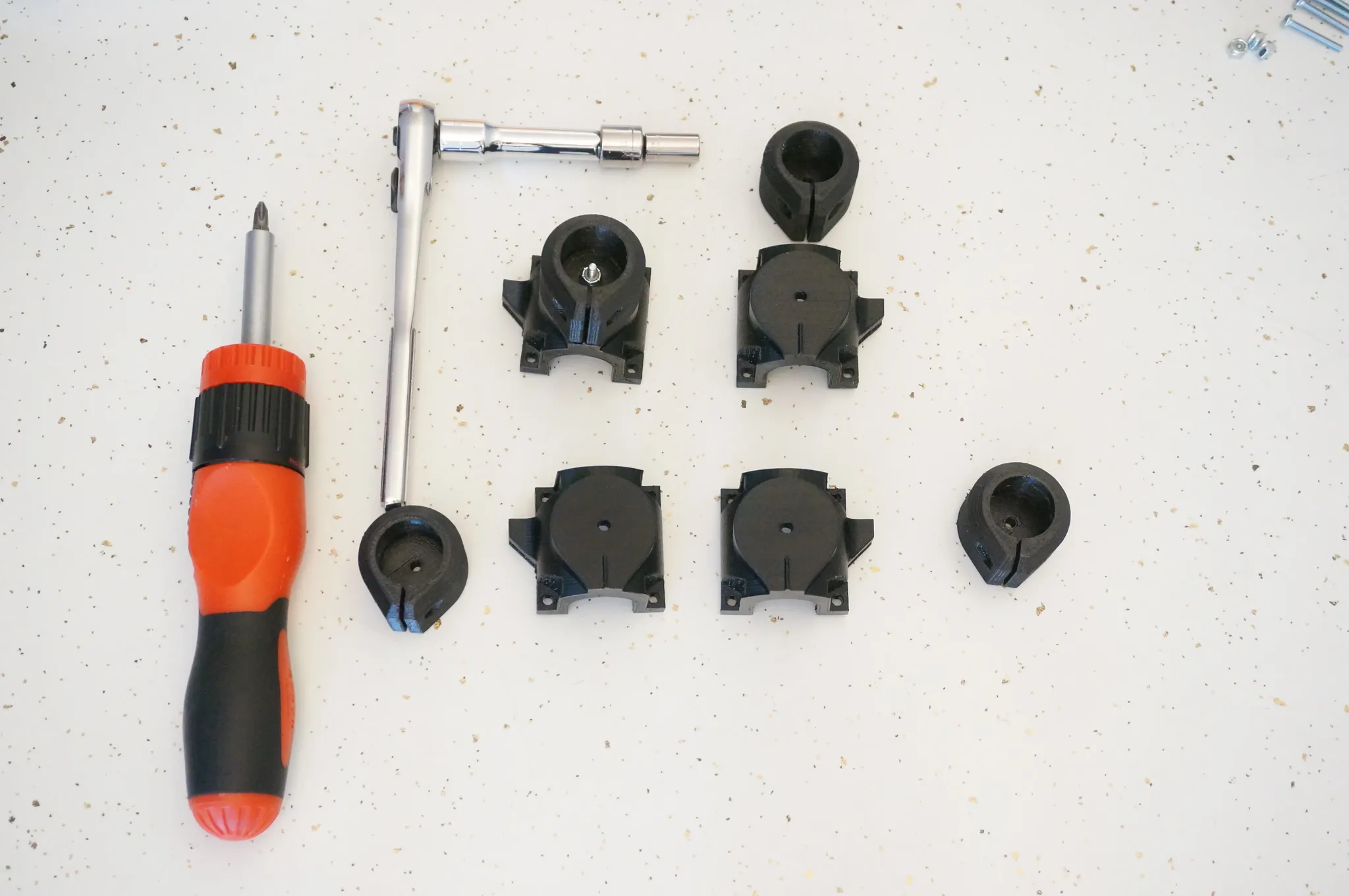
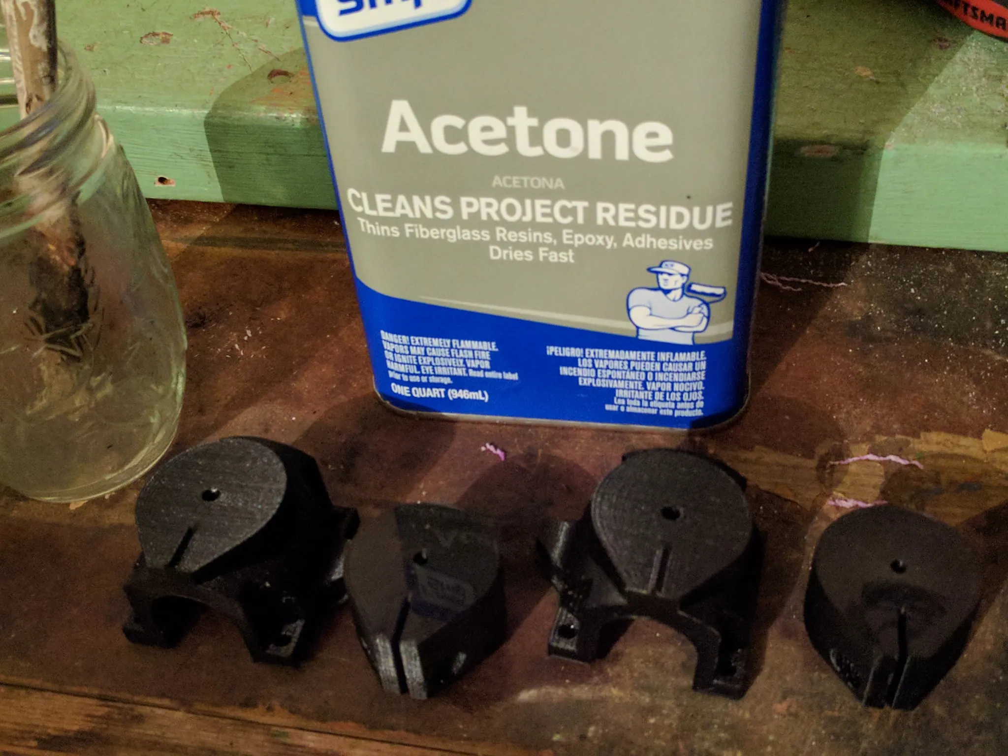
Optionally, glue or acetone weld these parts together.
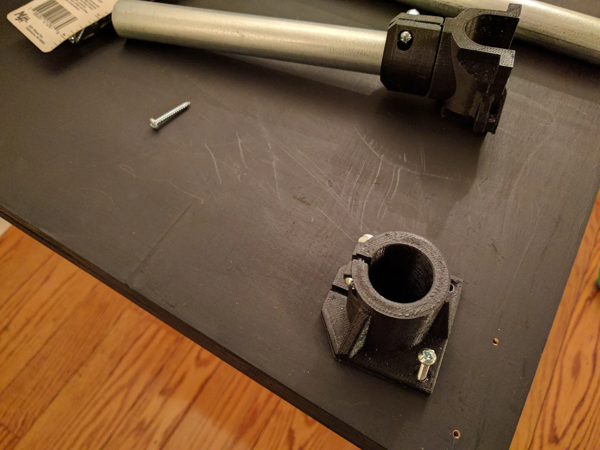
Then bolt them together.
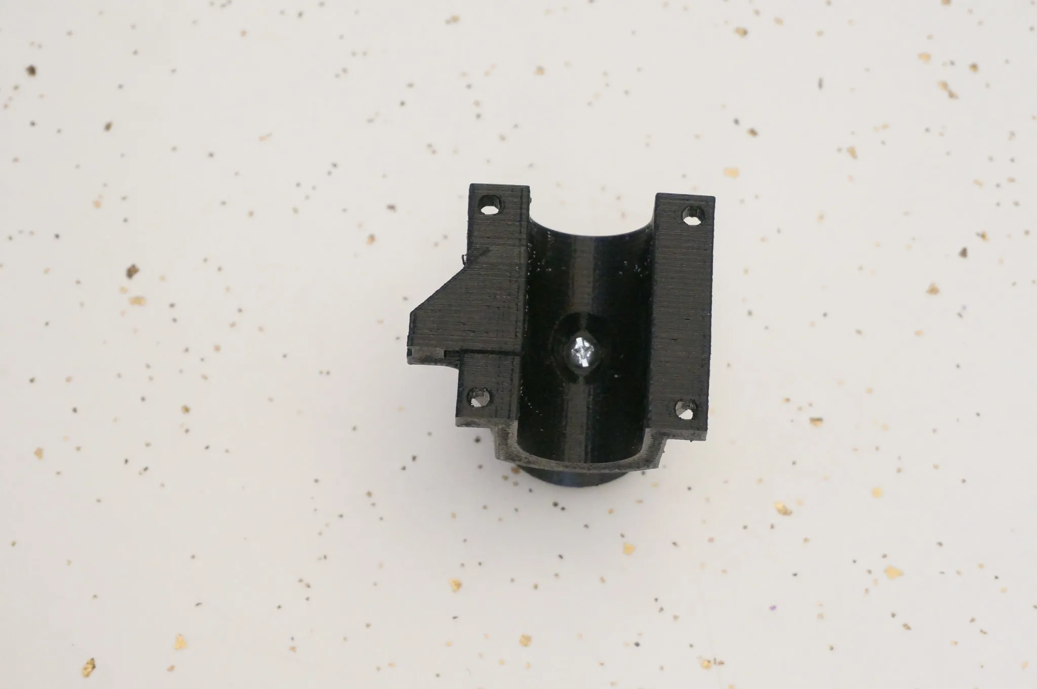
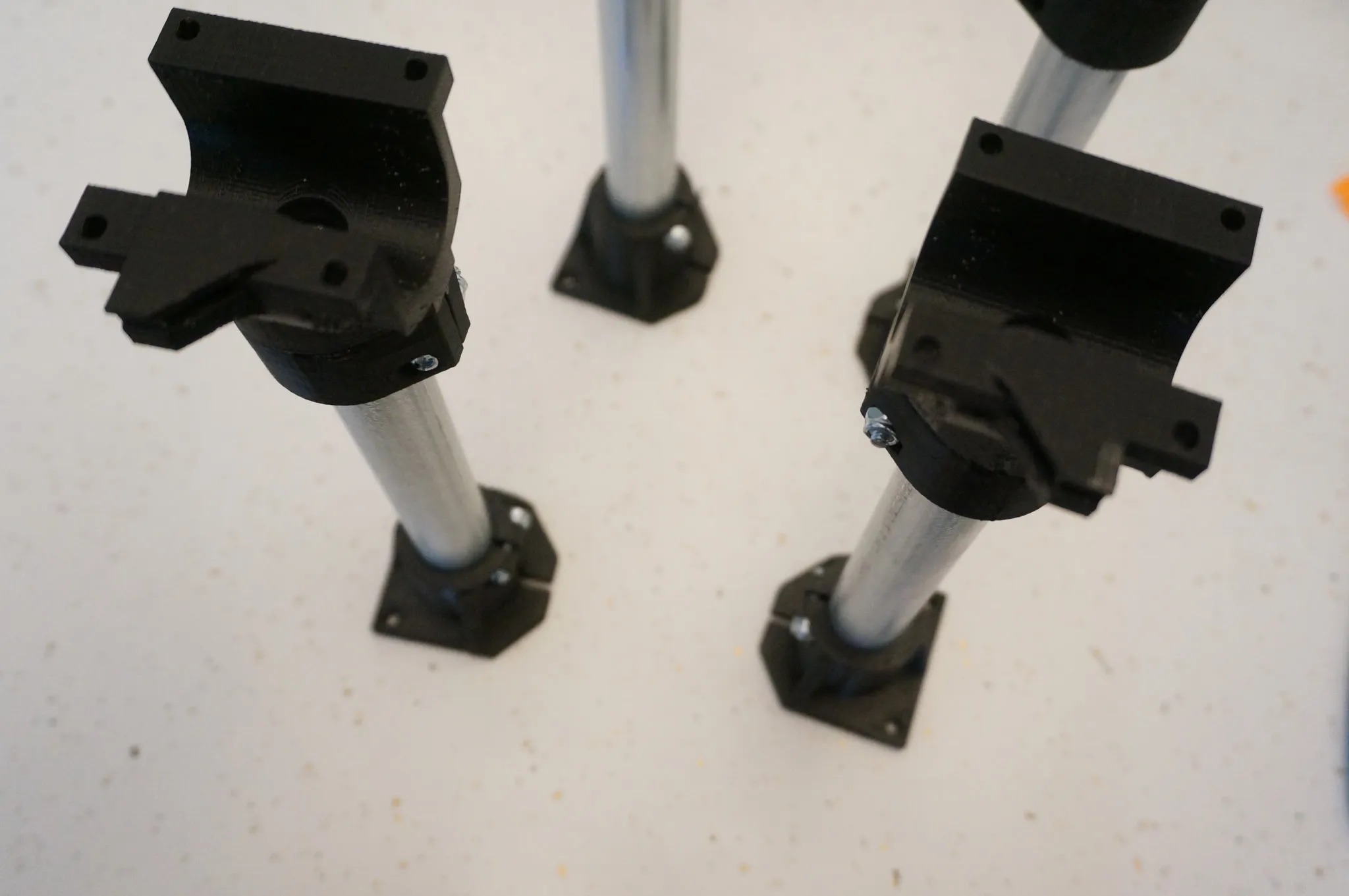
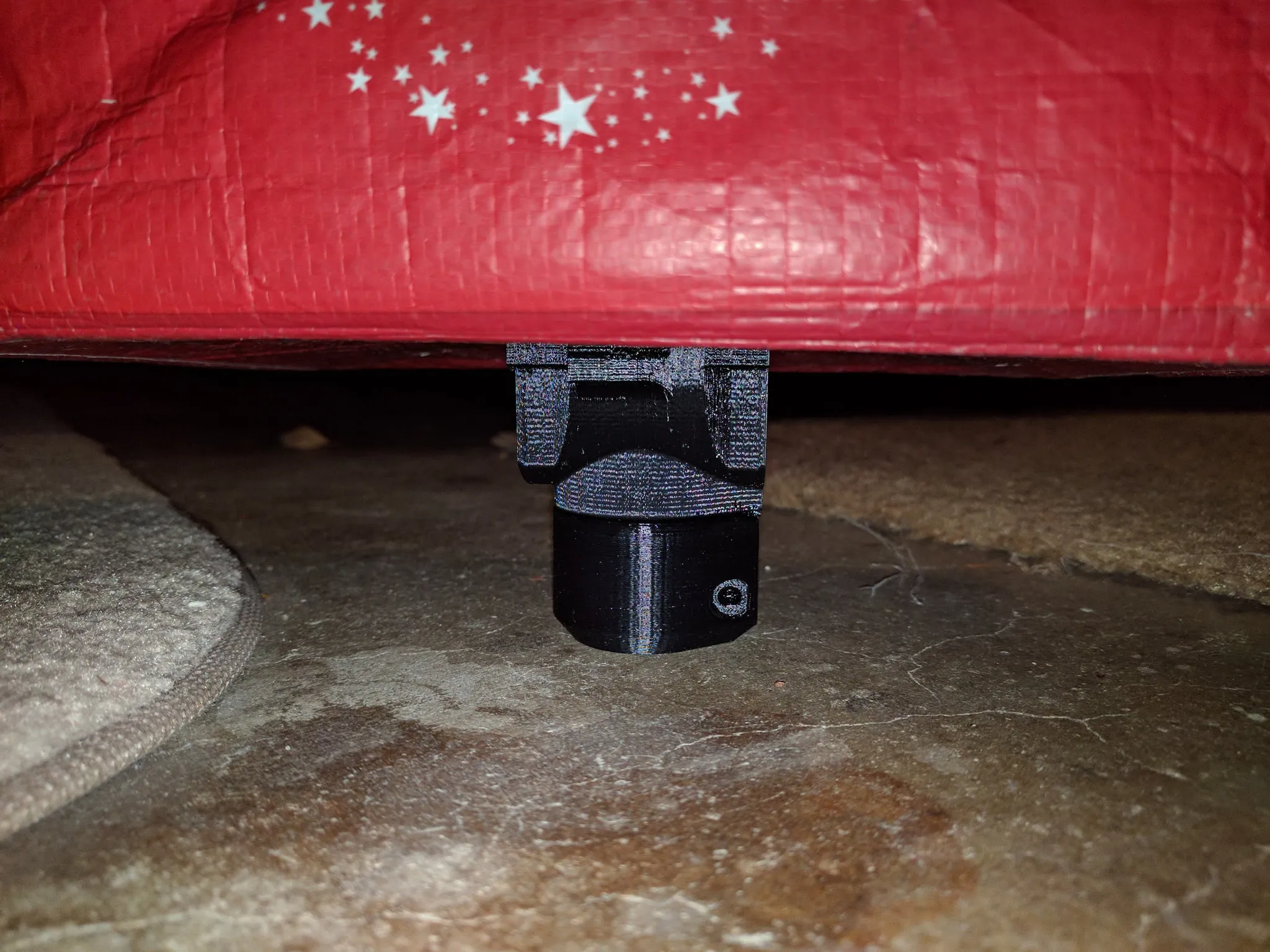
Then bolt onto the conduit leg.
Do all 4.
Then find the bottom parts for the legs and bolt those on as well.
X-Y Axis
Grab the printed parts and your shorter bolts.
Note how the bolts overhang the nuts by a 1/4”. It would probably be fine like this, but I don’t like the way they look.

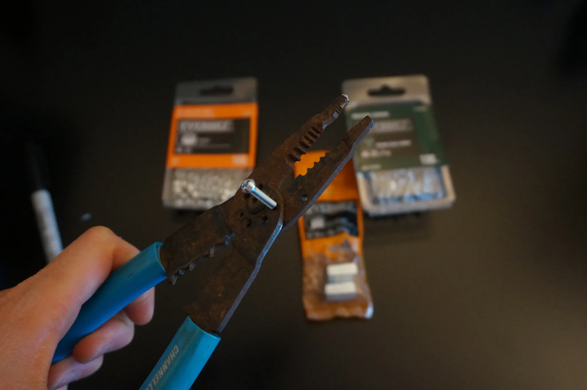
I couldn’t find 1-1/4” bolts locally, so I used 1-1/2” bolts and cut them down with a hacksaw then cleaned them up with a file. I found cutting 5 grooves up from the end was the perfect length.
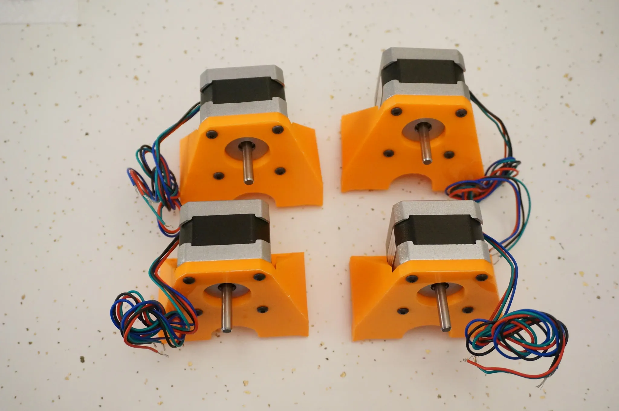
Find the longer bolts, lock nuts, and 4 more bearings.
Note the bolt direction.
Fasten the nuts.
Complete all 4.
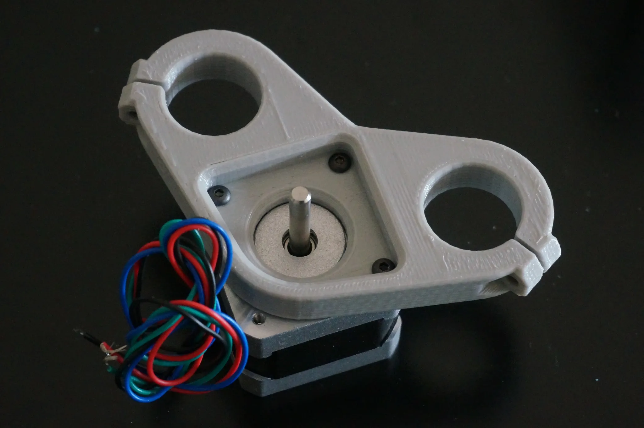
I’m using 3mm x 10mm hex bolts to attach the steppers to the 3D printed mount.
Bolt them on like this.
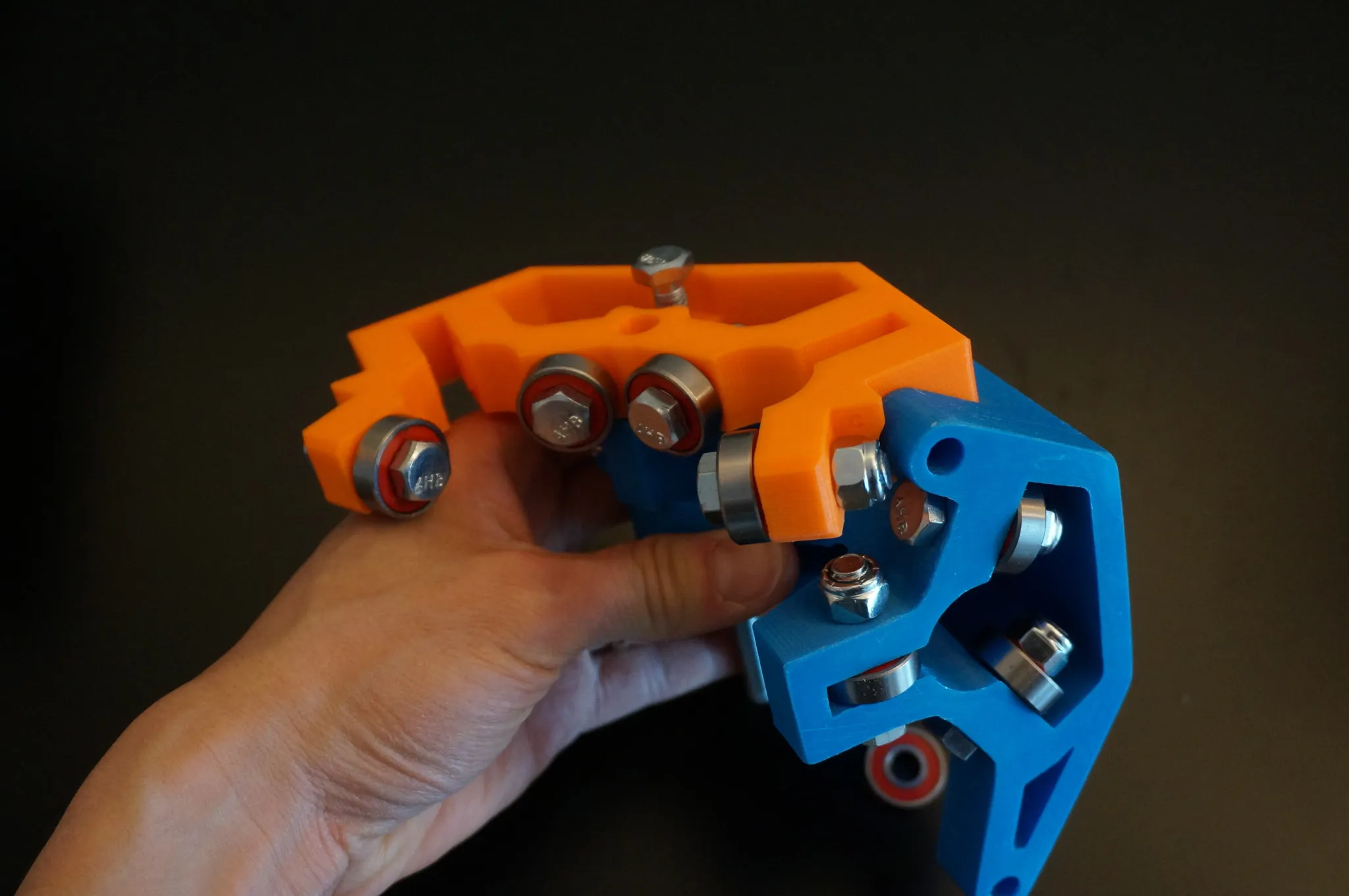
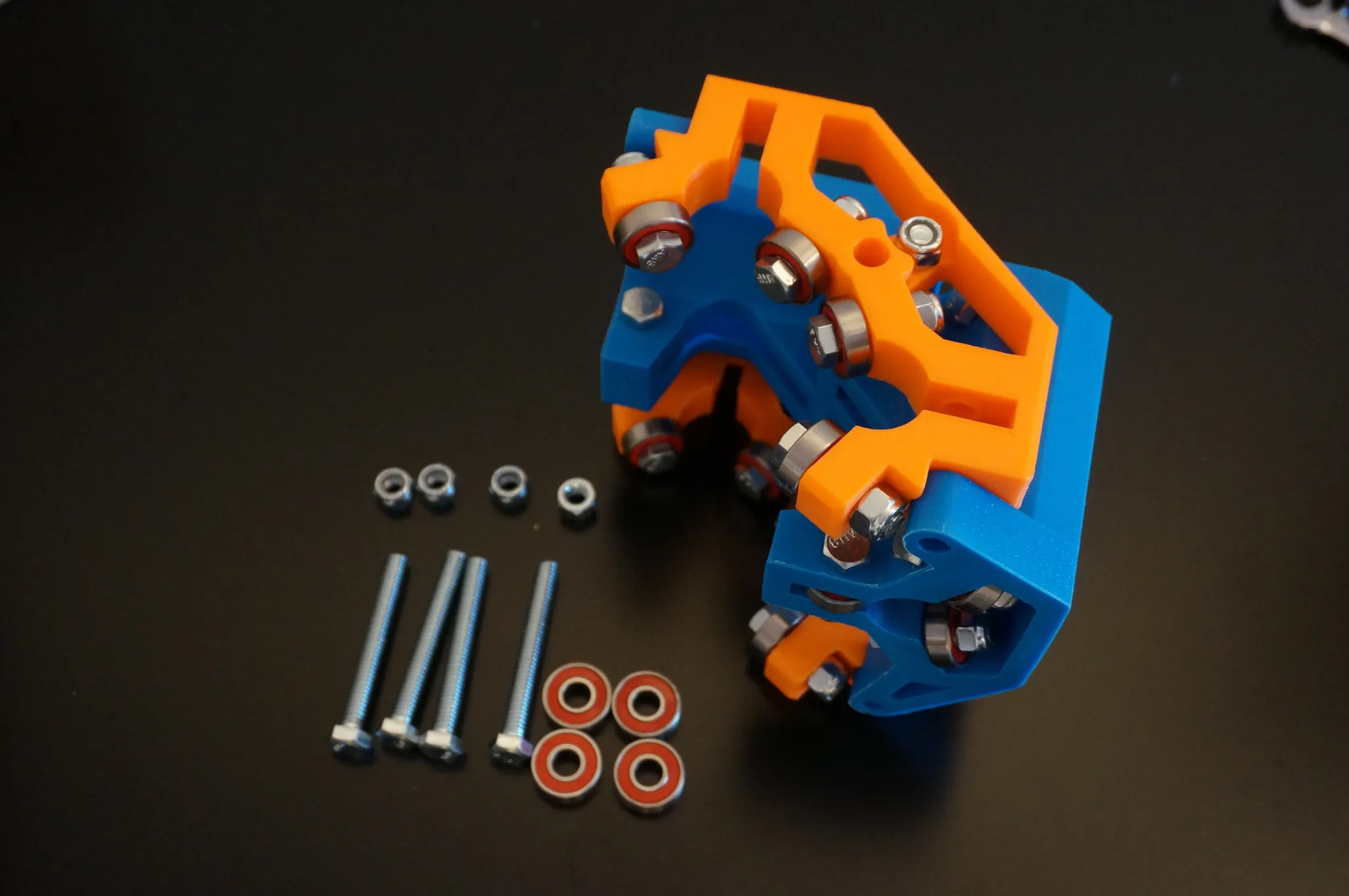
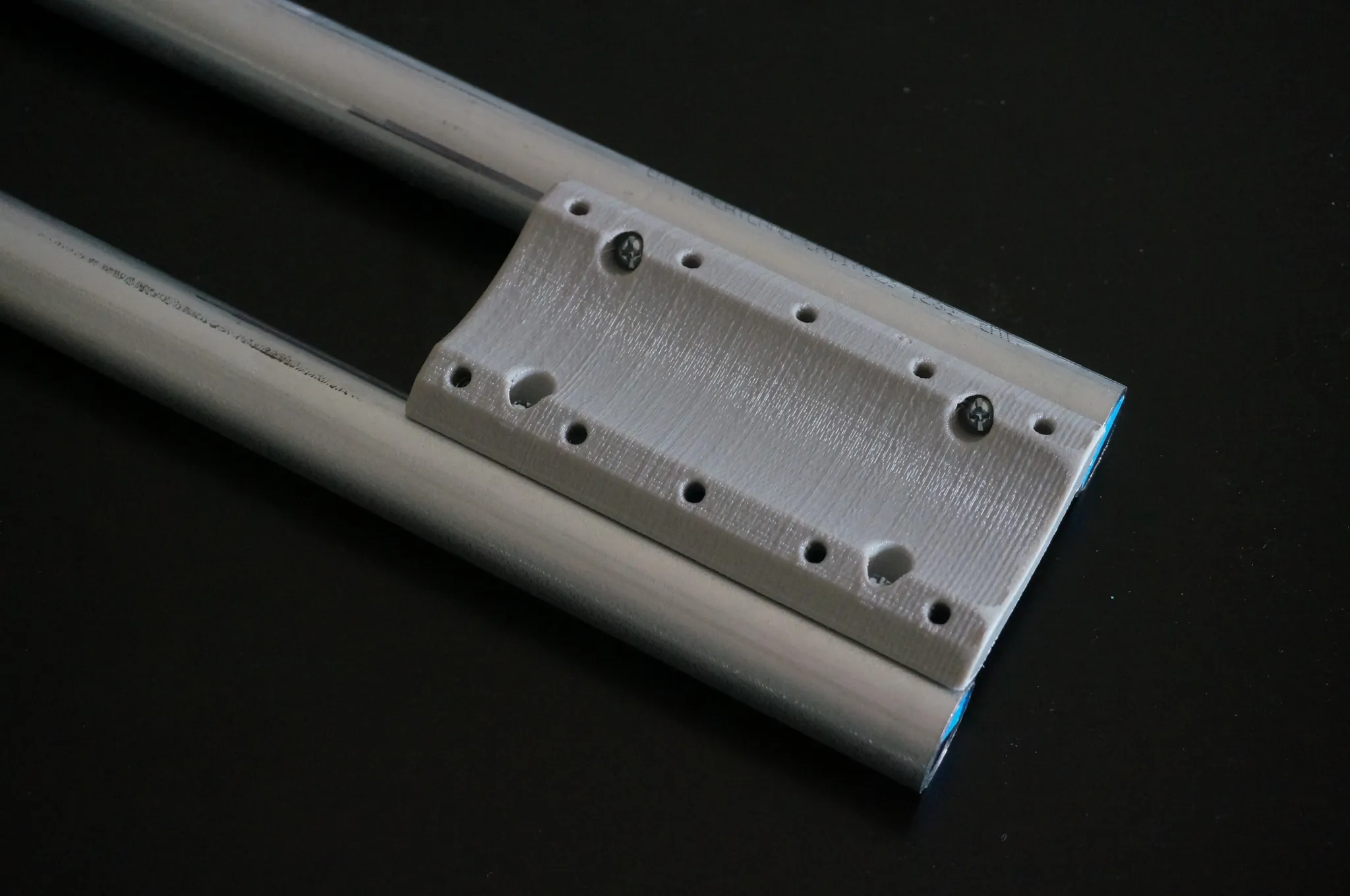
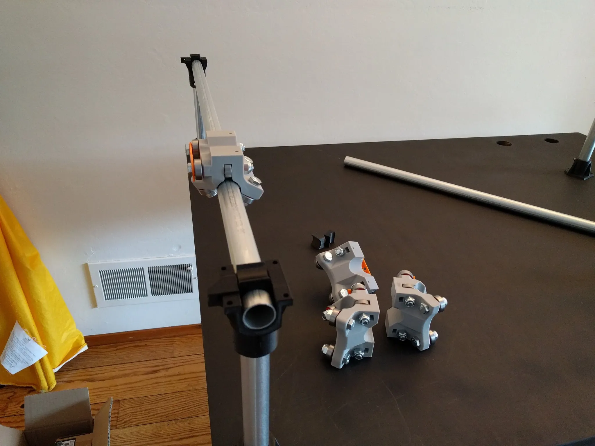
Carriage
This part is slightly tricky, just follow the pictures and you’ll do great. Unfortunately, I can’t give more detailed written directions since I’m not sure of the names of some of these parts.
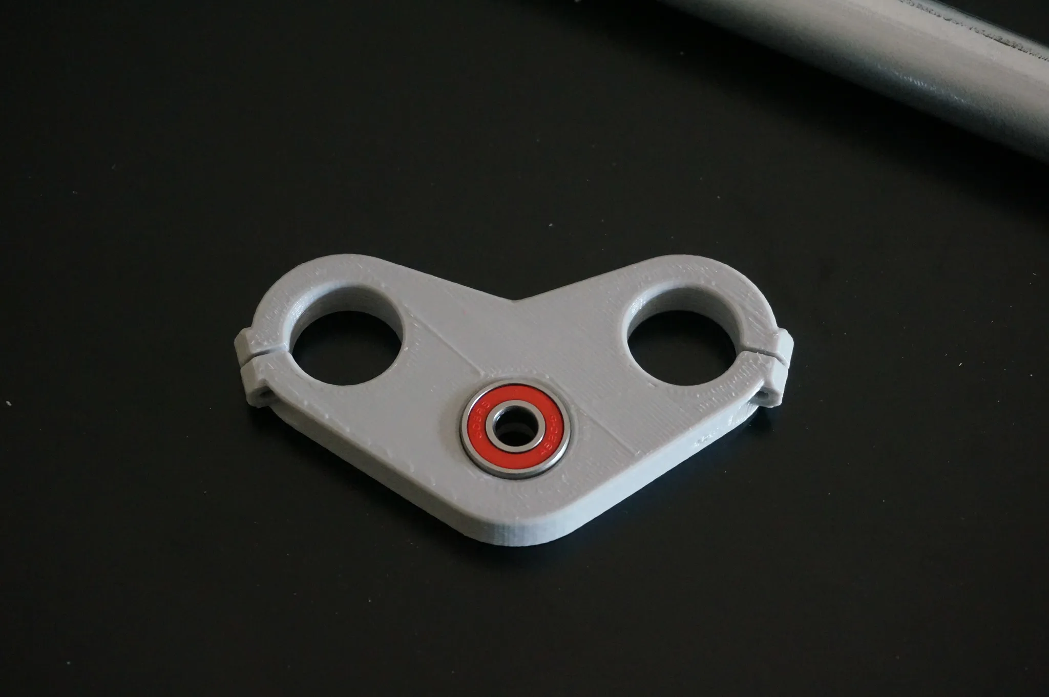
Grab this part… see, no idea what to call it… and some bolts.
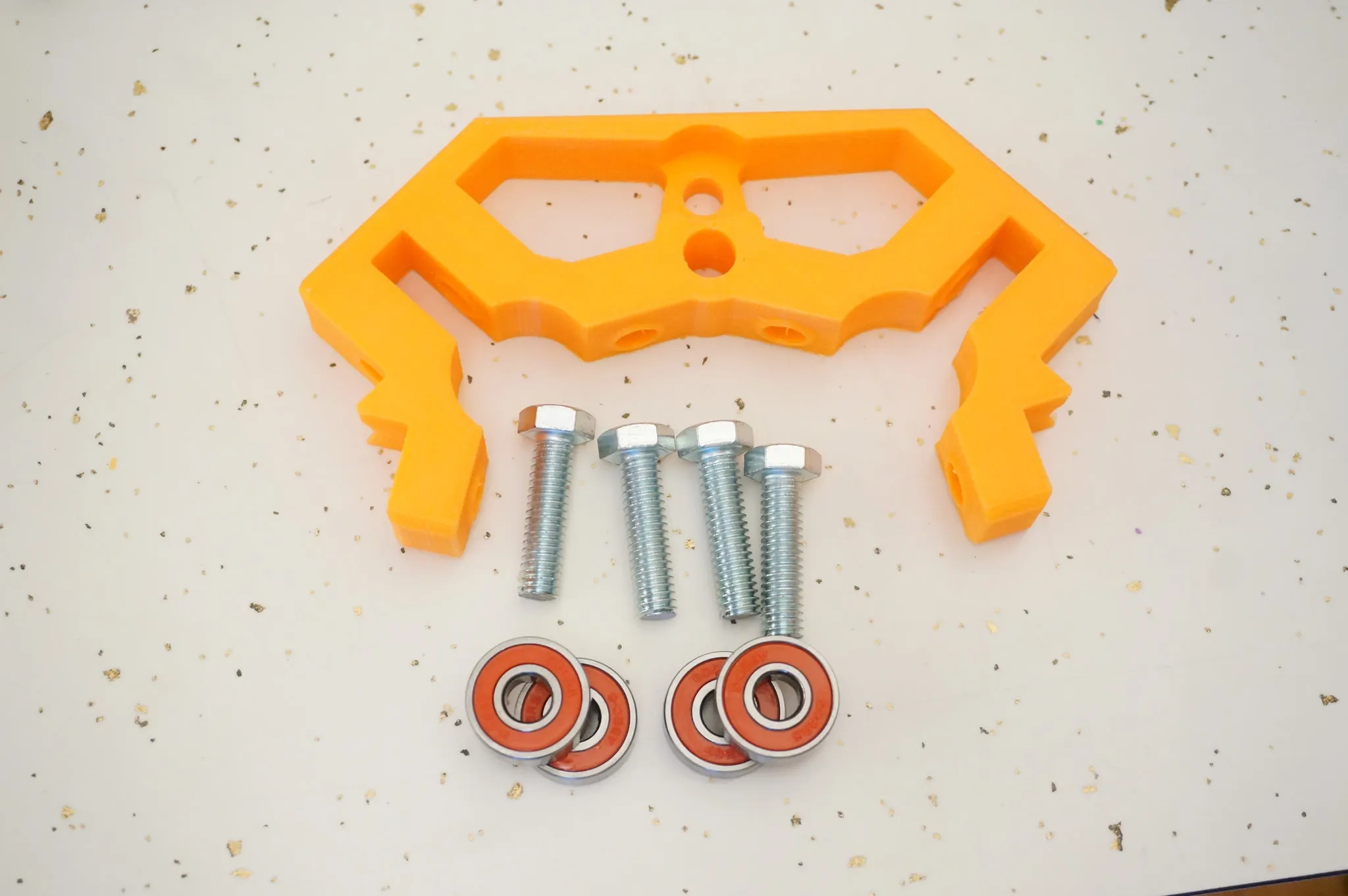
Bolt on the bearings.
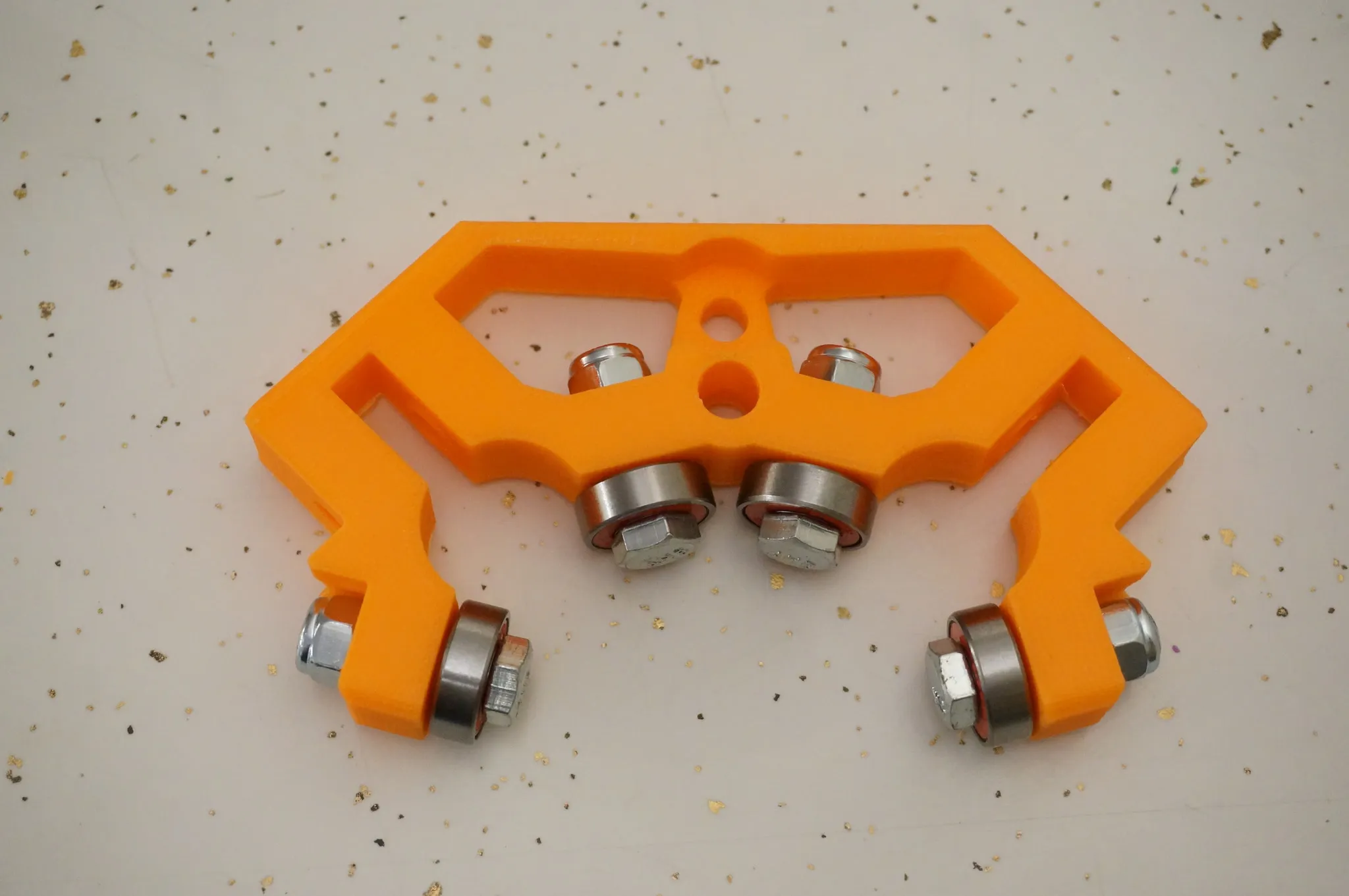
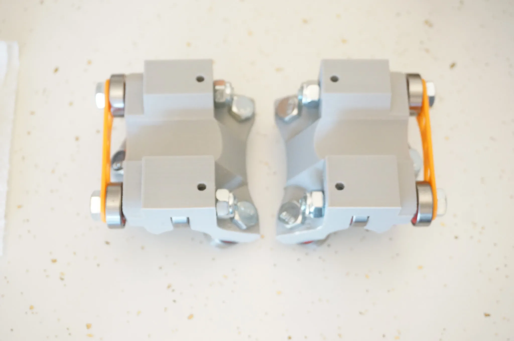
And do the other one as well.
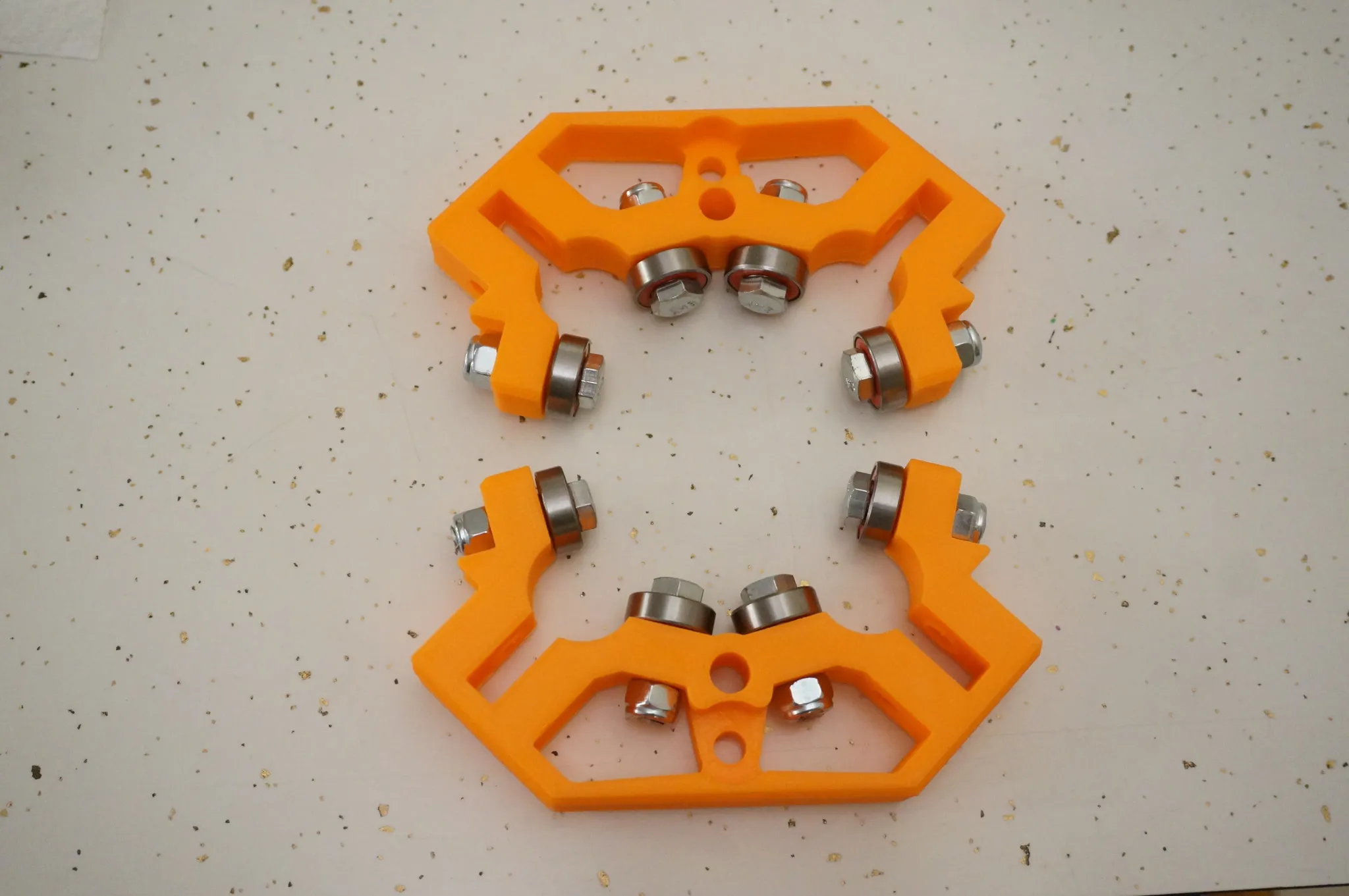
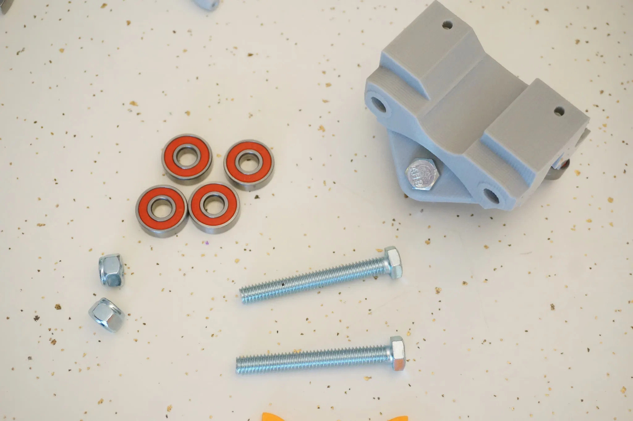
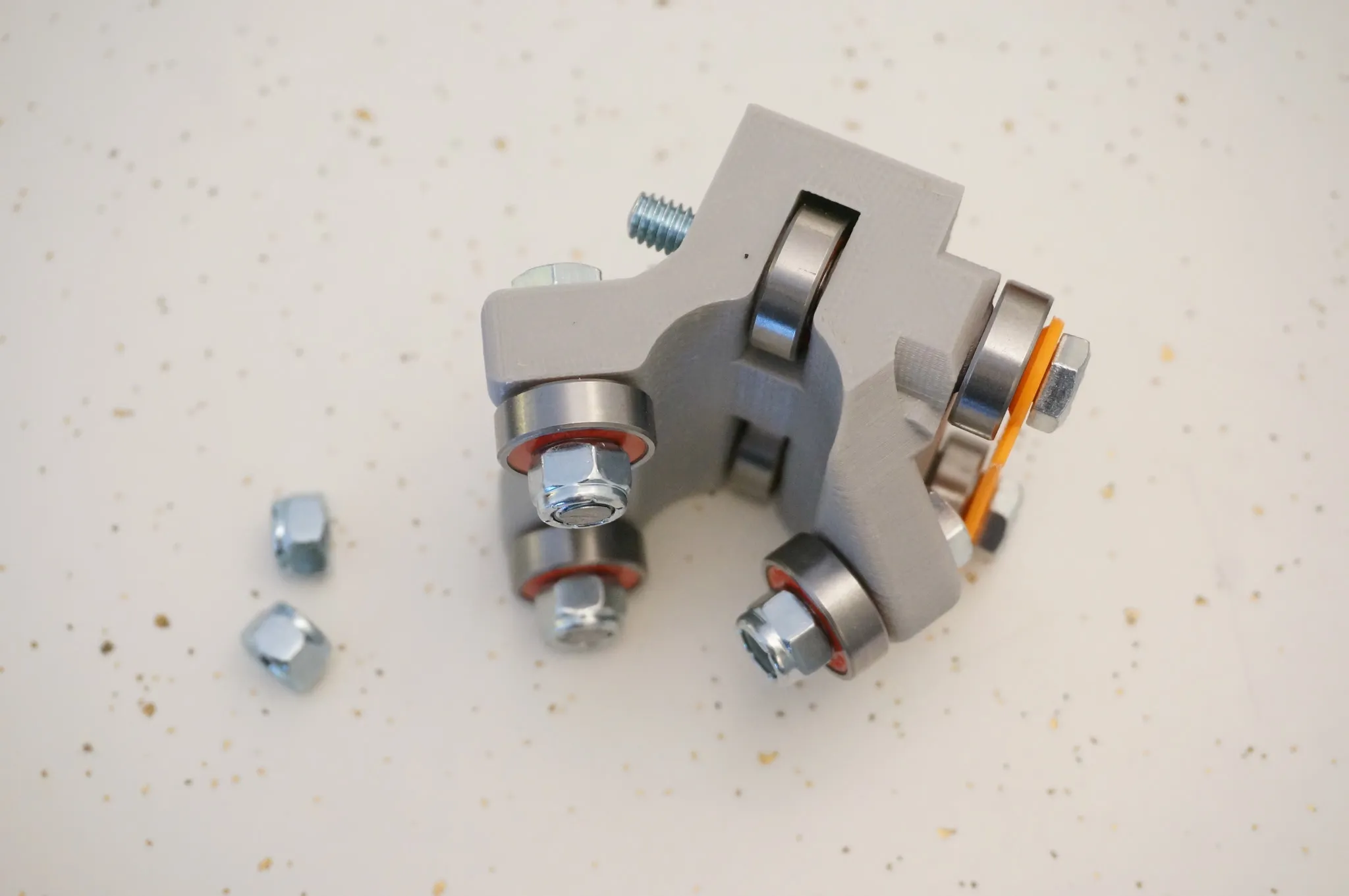
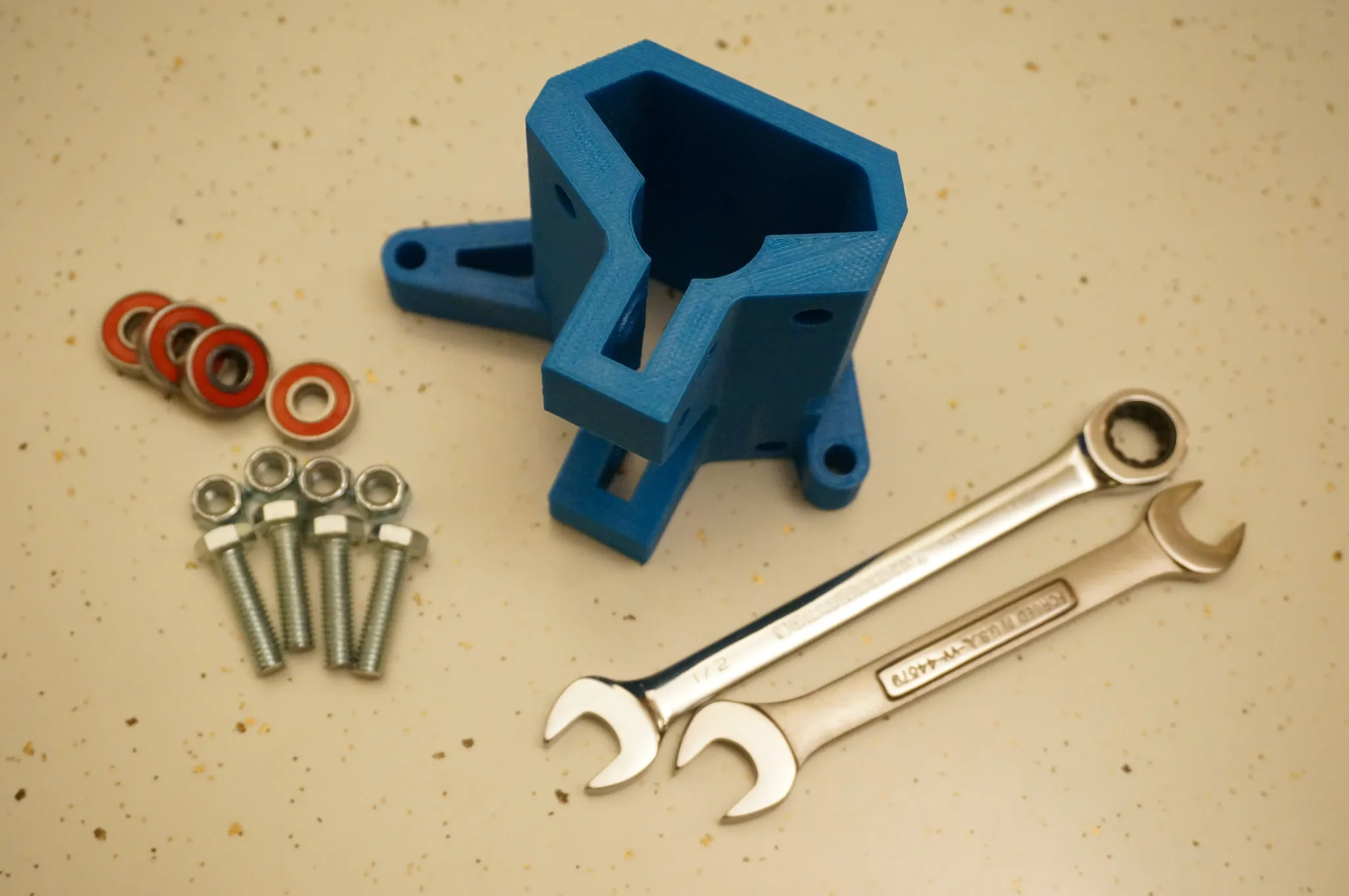
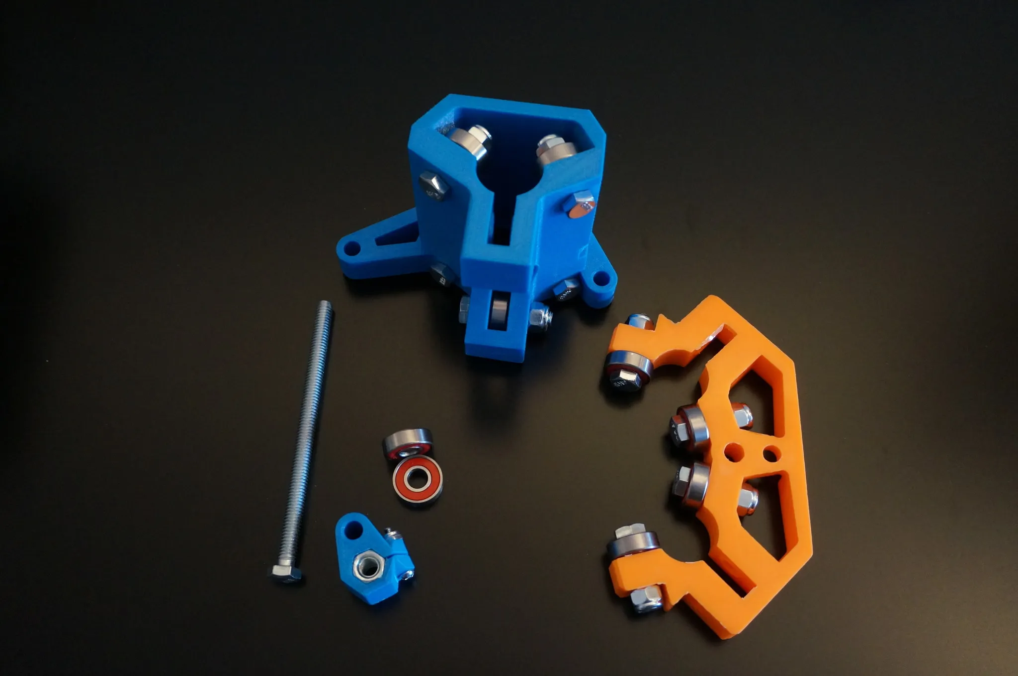
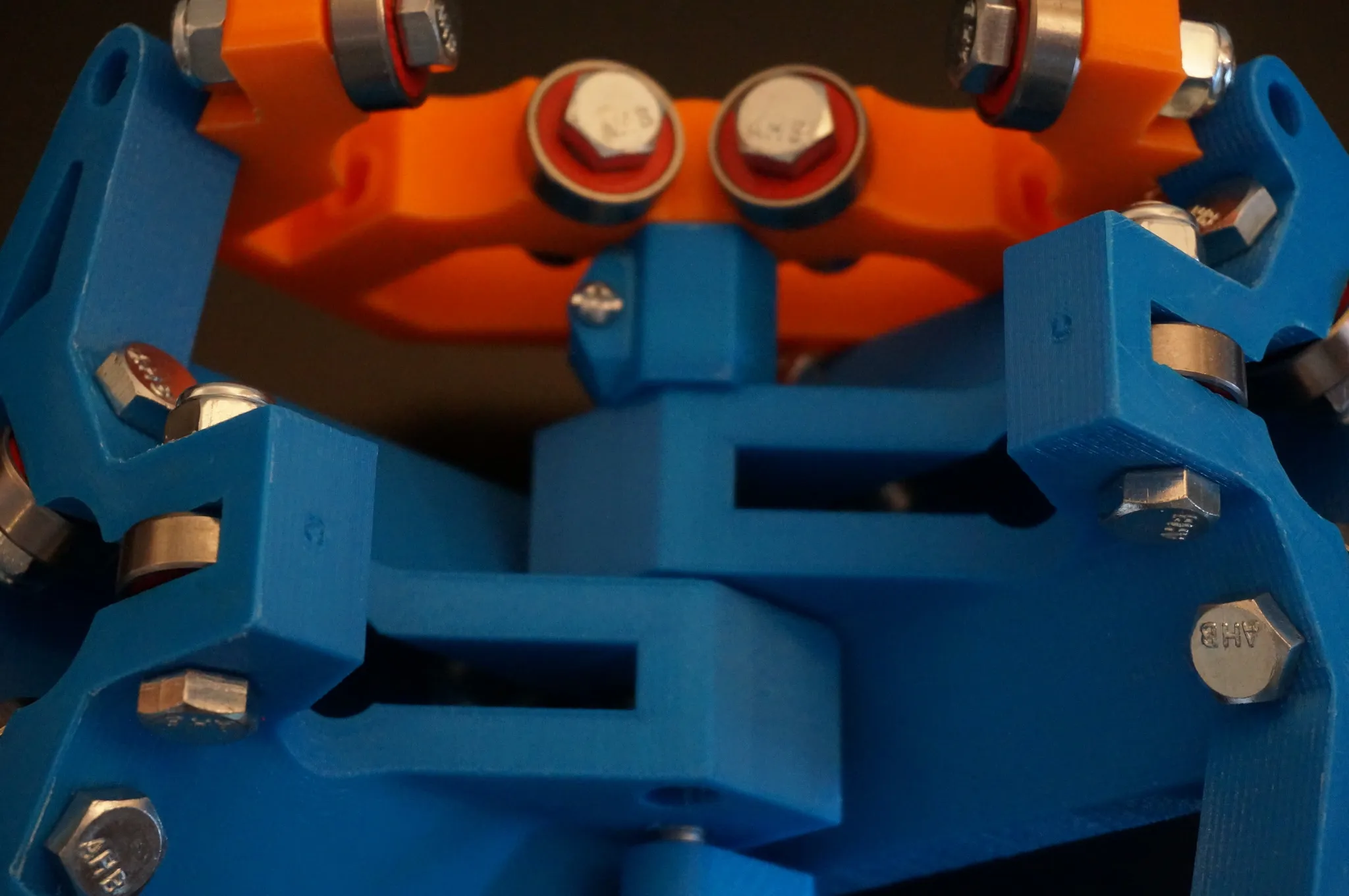
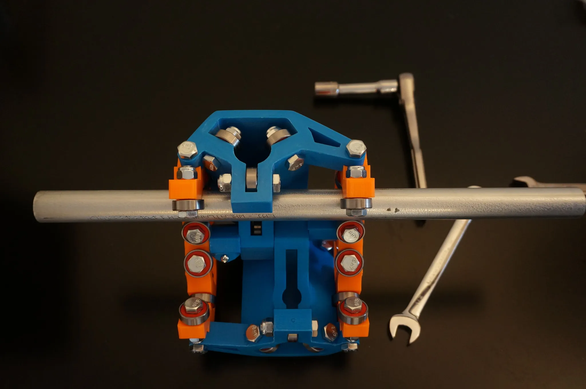
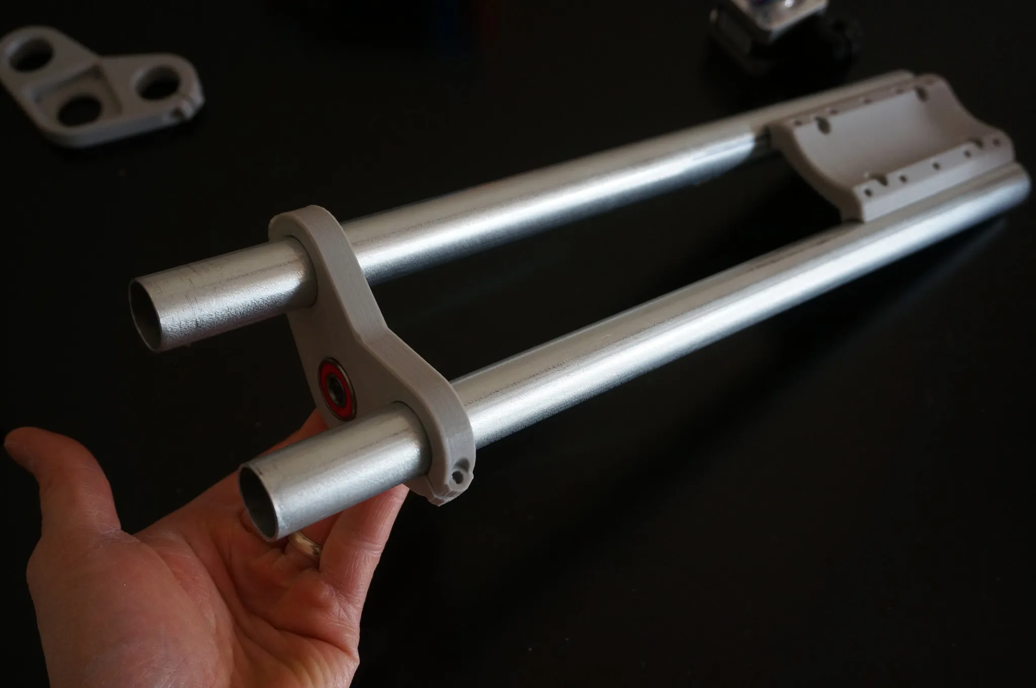
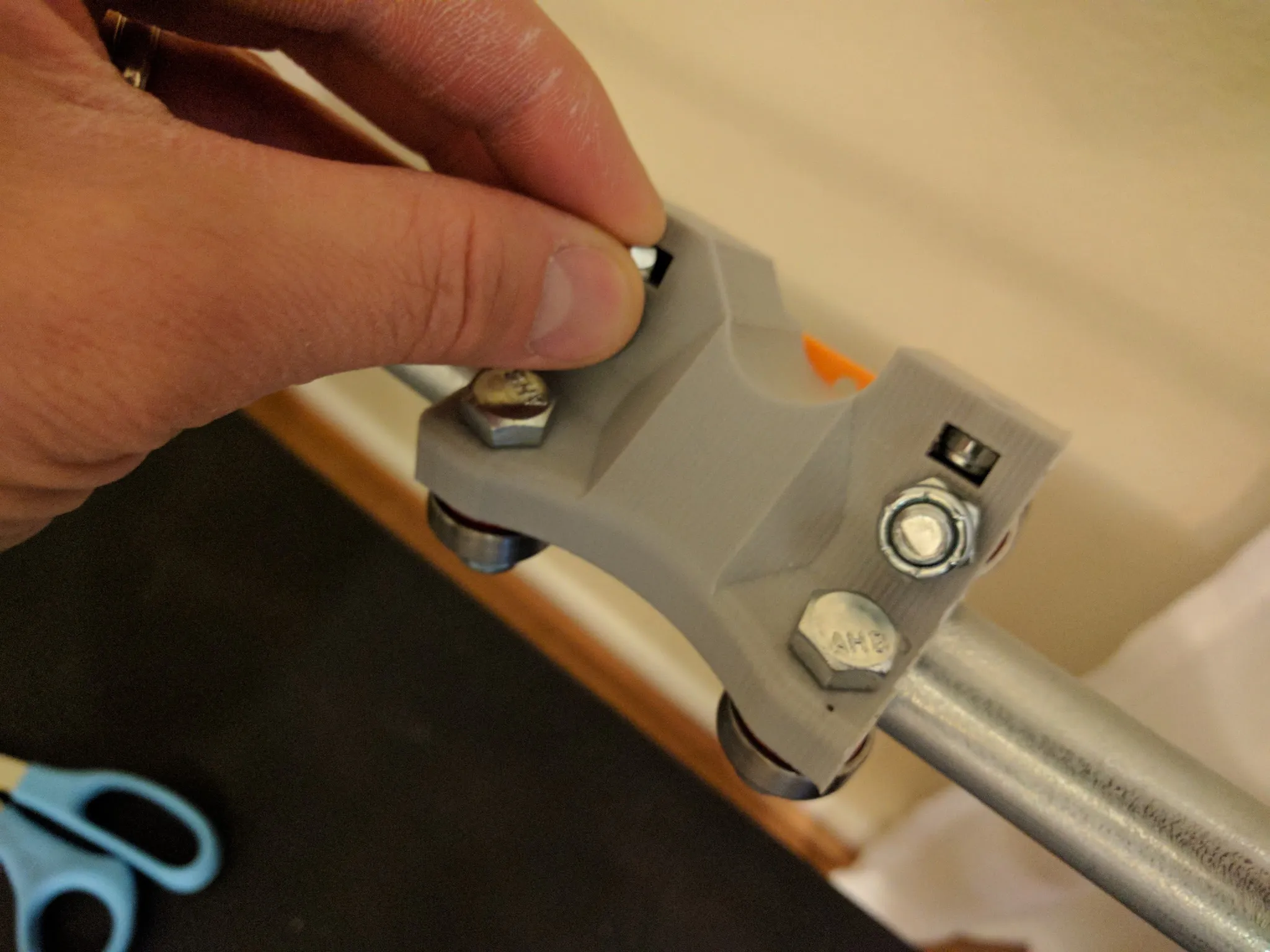
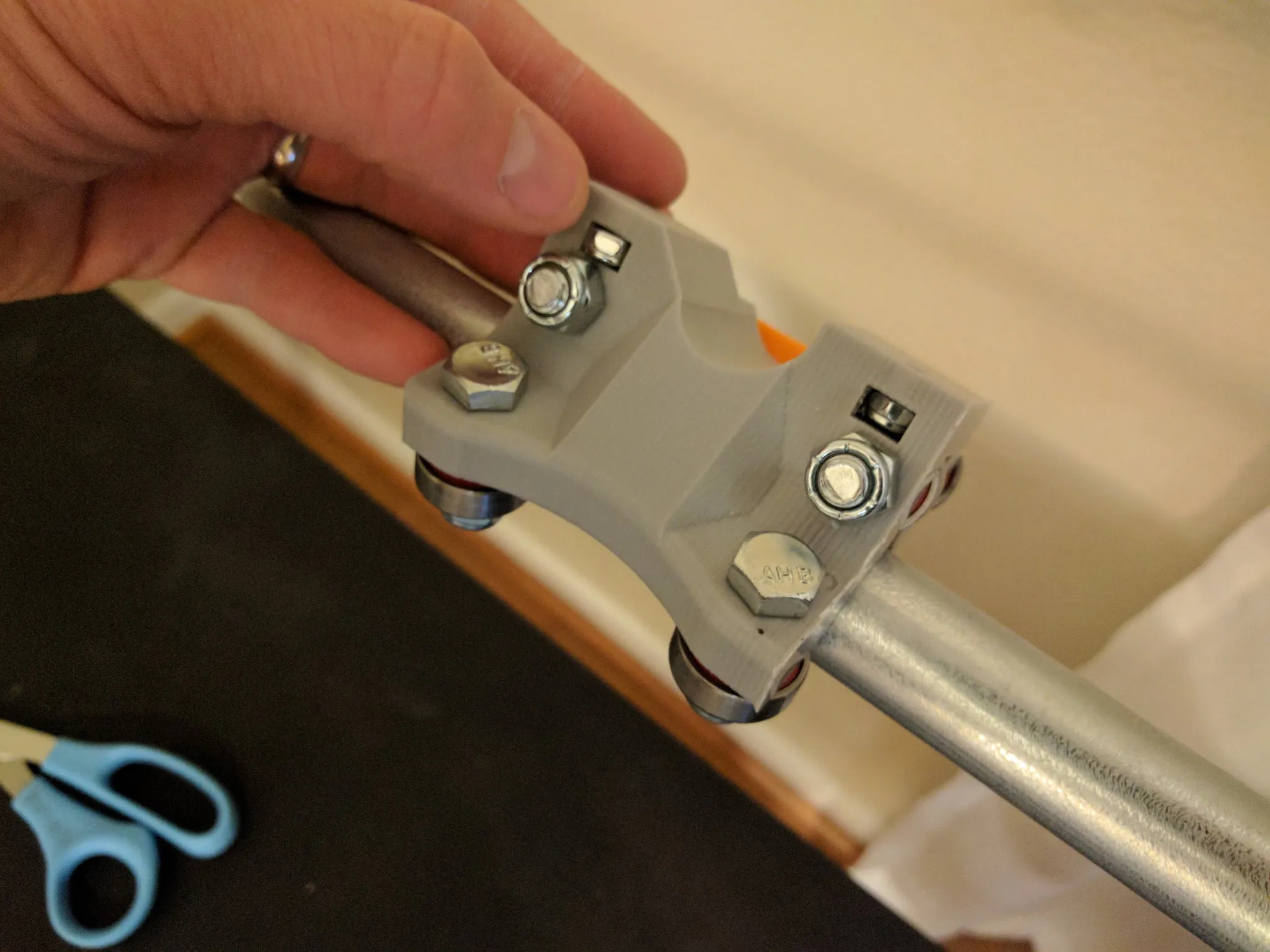
Now you’ll need one of the large center sections, bolts, nuts, bearings, and a couple of wrenches.
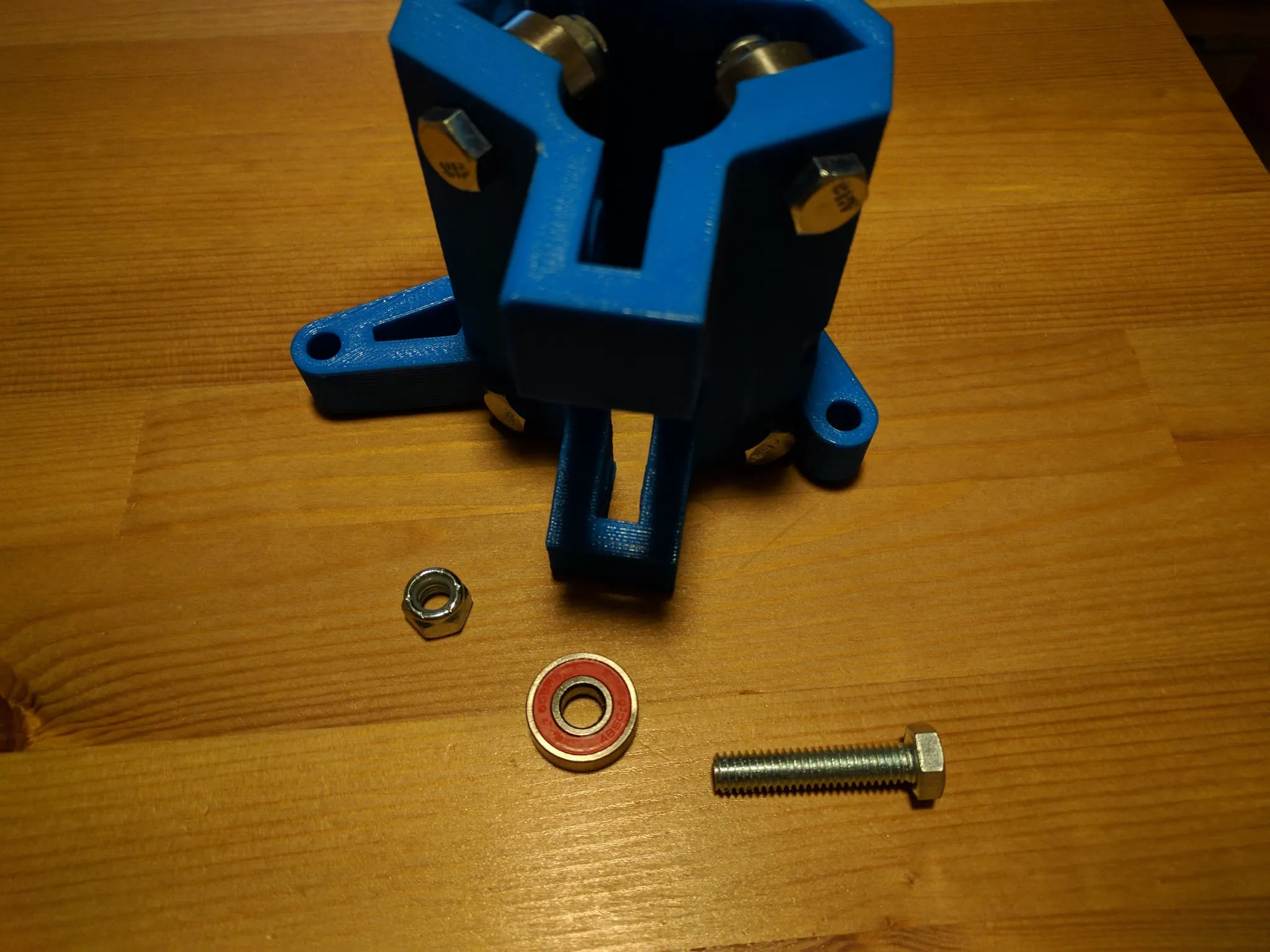
Install the bearings like so for both parts (only 1 is shown here).
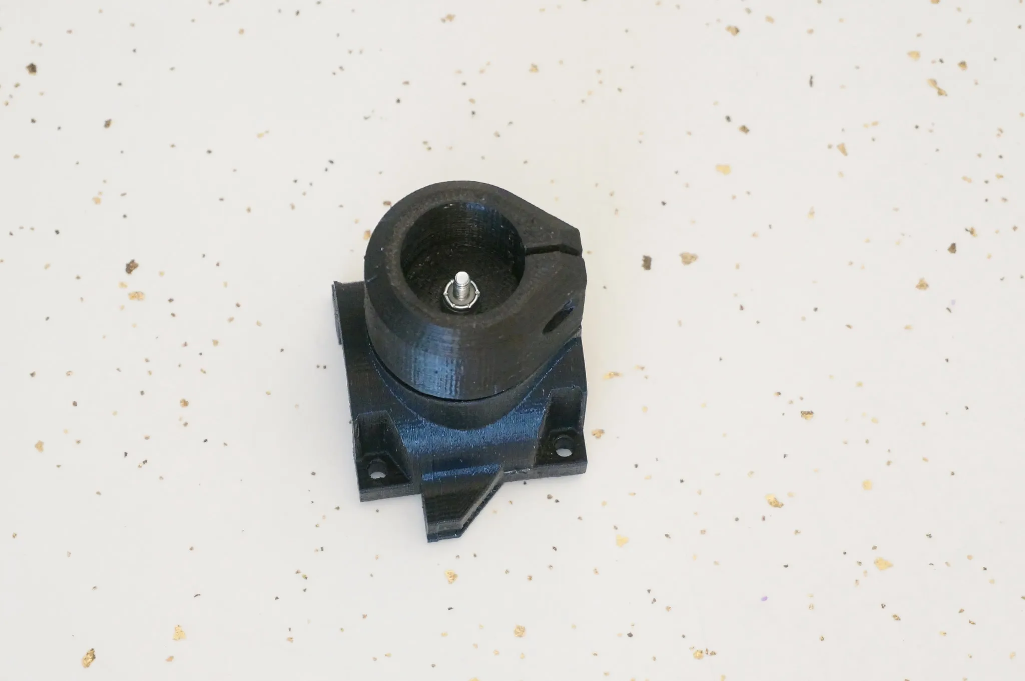
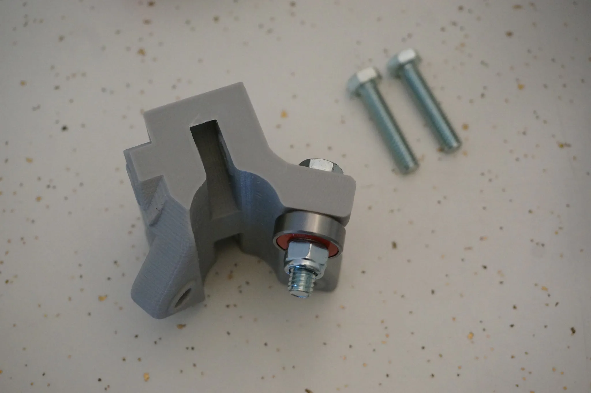
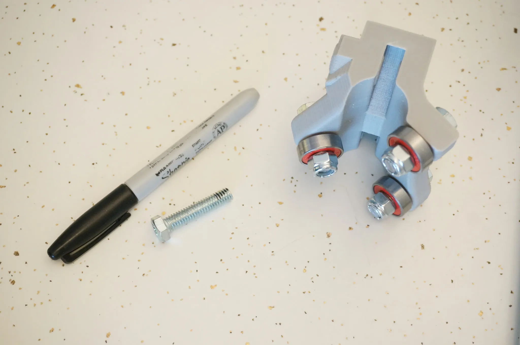
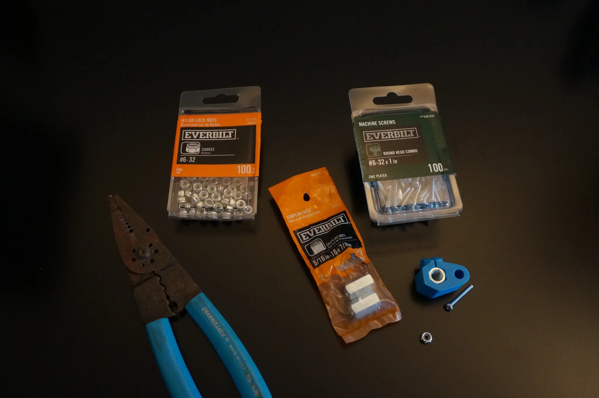
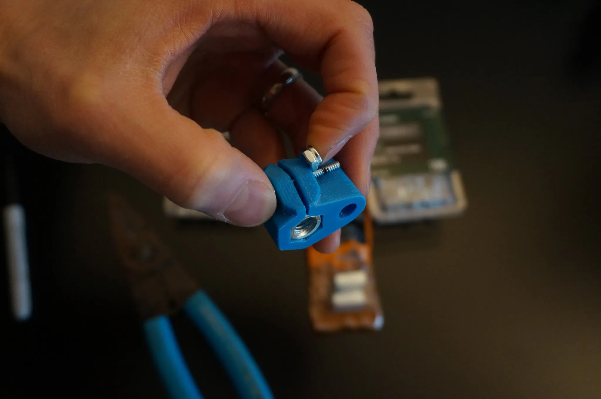
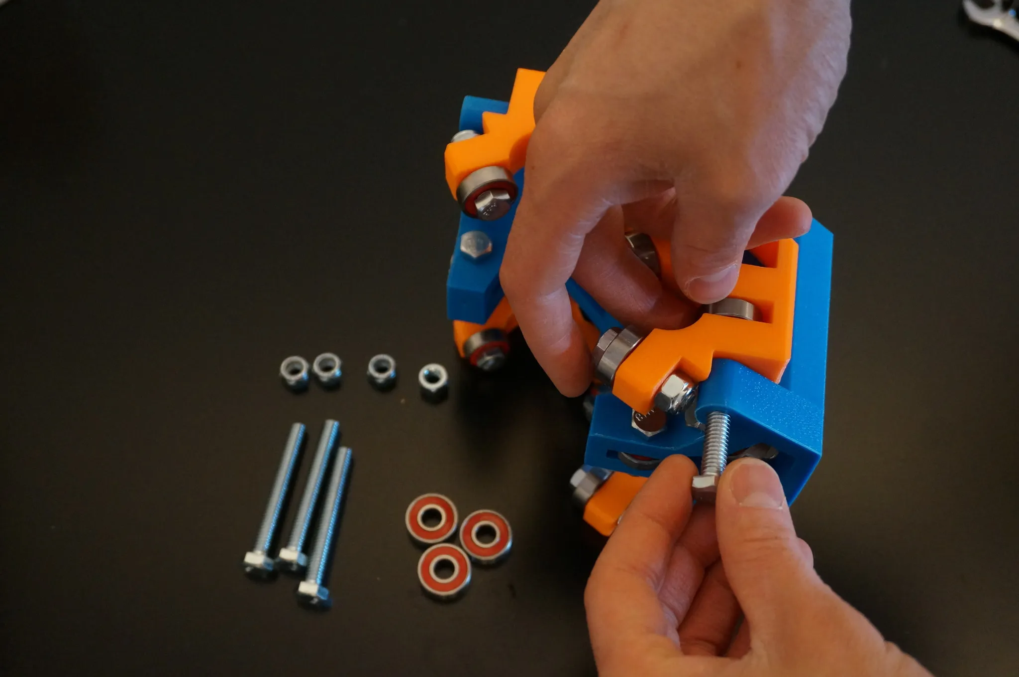
Now find the coupler nut, a small bolt and nut, and the 3D printed part. Install the coupler nut into the 3D printed part.
Mark the bolt.
Cut it down to size. Alternatively, use a hacksaw for this.
Now find your partially assembled pieces.
Insert the long bolt.
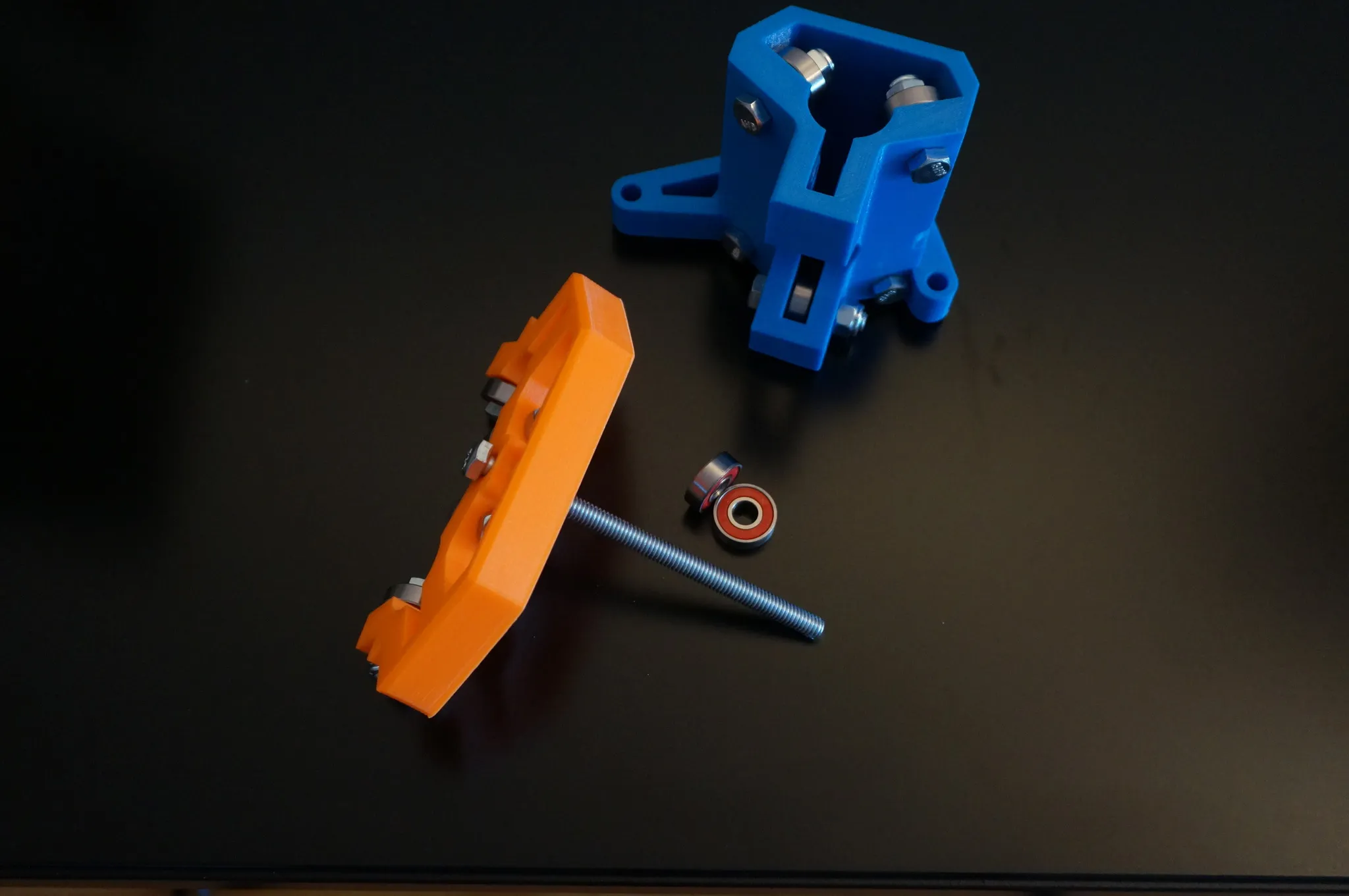
Add the coupler, put the bolt through the hole without the coupler nut.
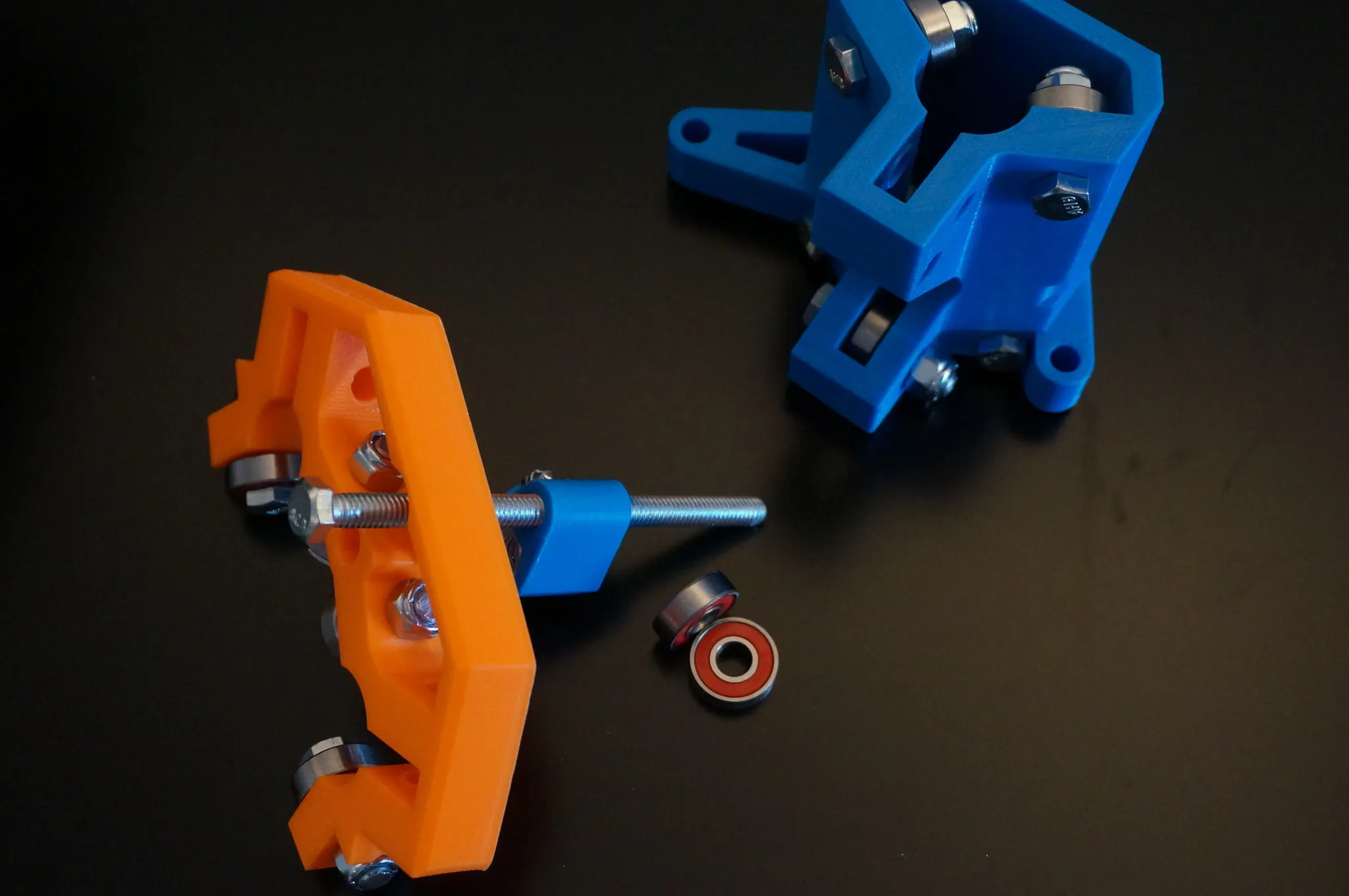
Then through the blue part.
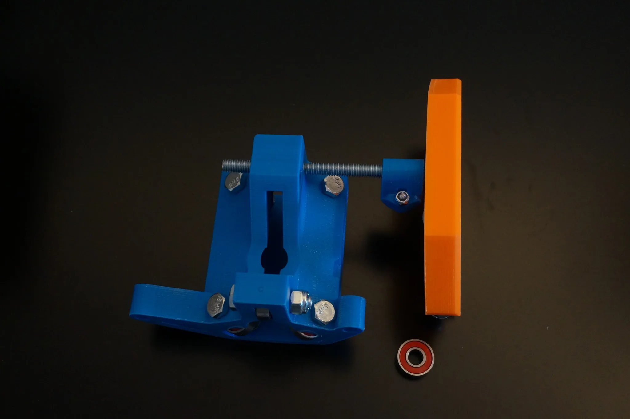
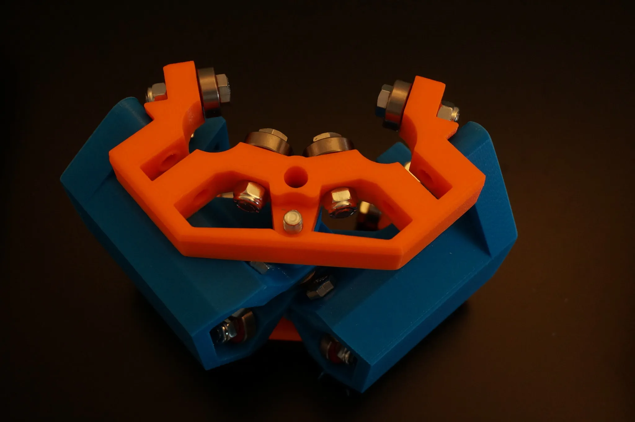
It will fit like this.
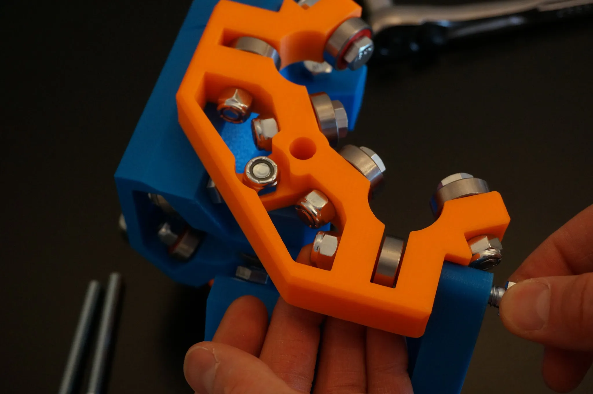
Add the other middle blue piece.
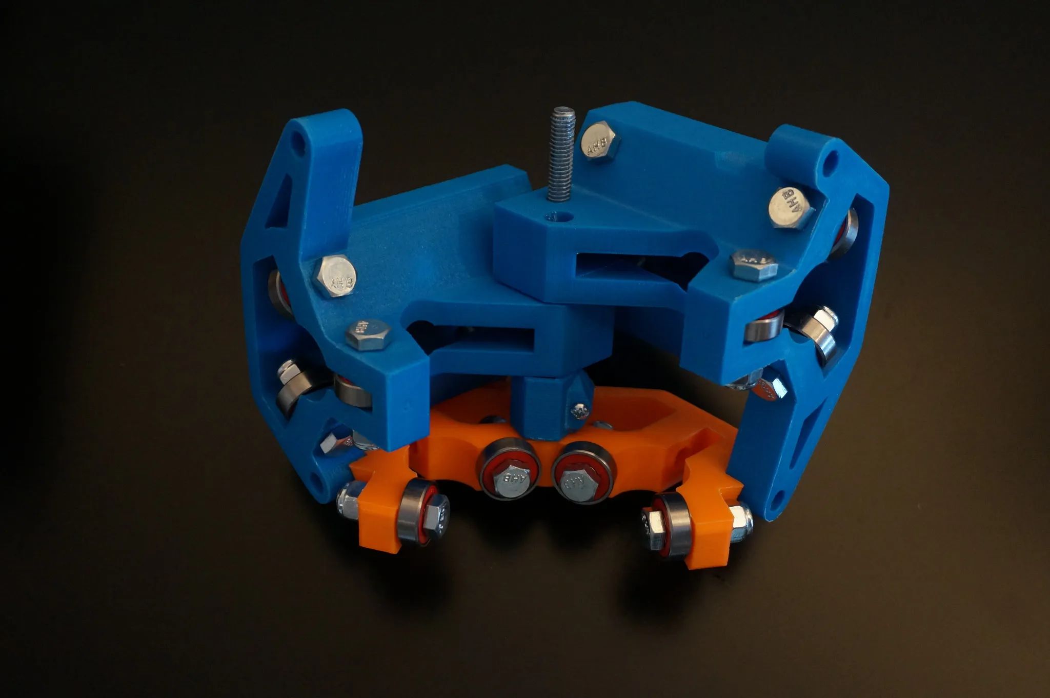
Add the bottom spacer.
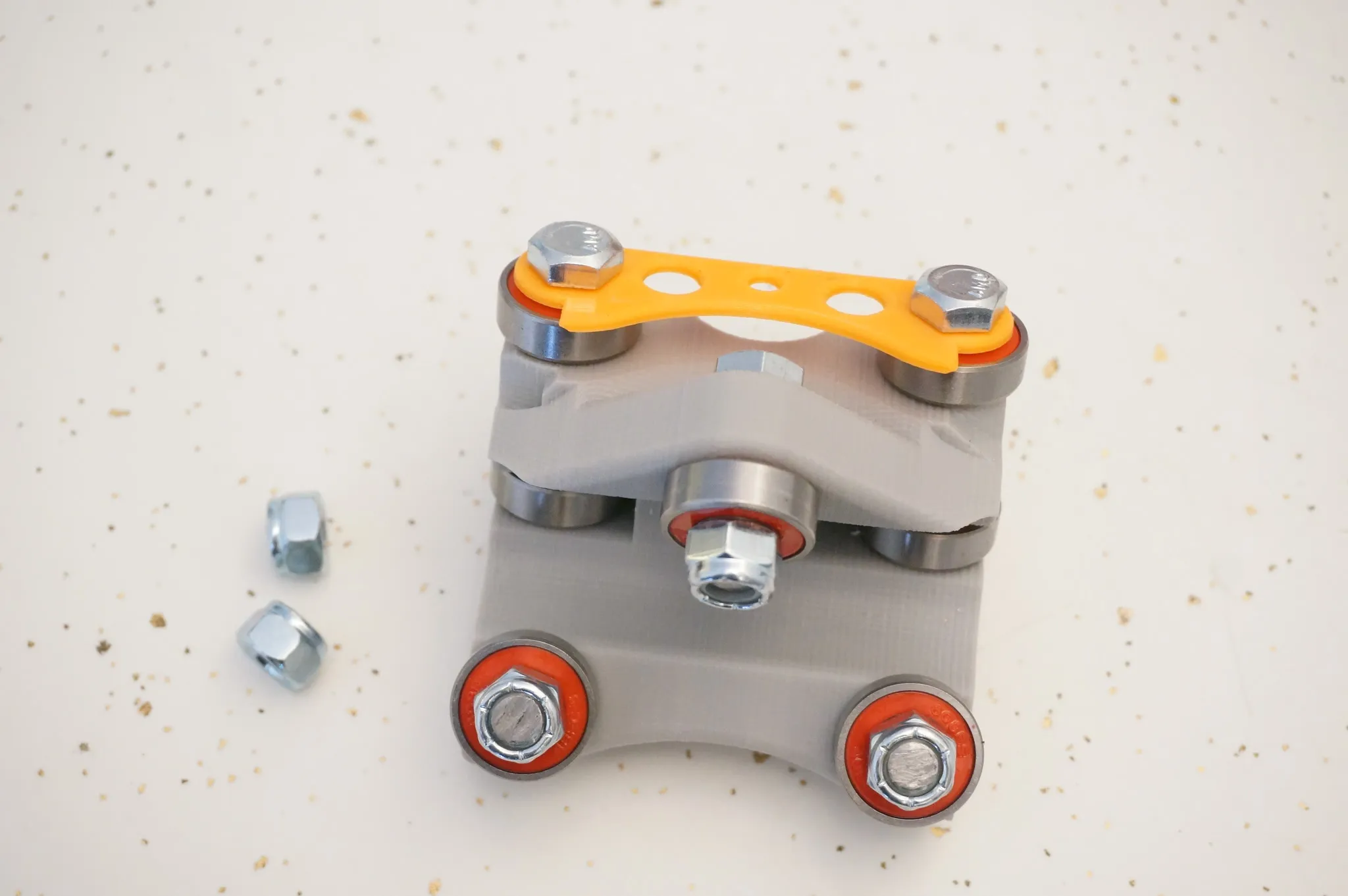
Then add the bottom orange piece.
Bolt it on.
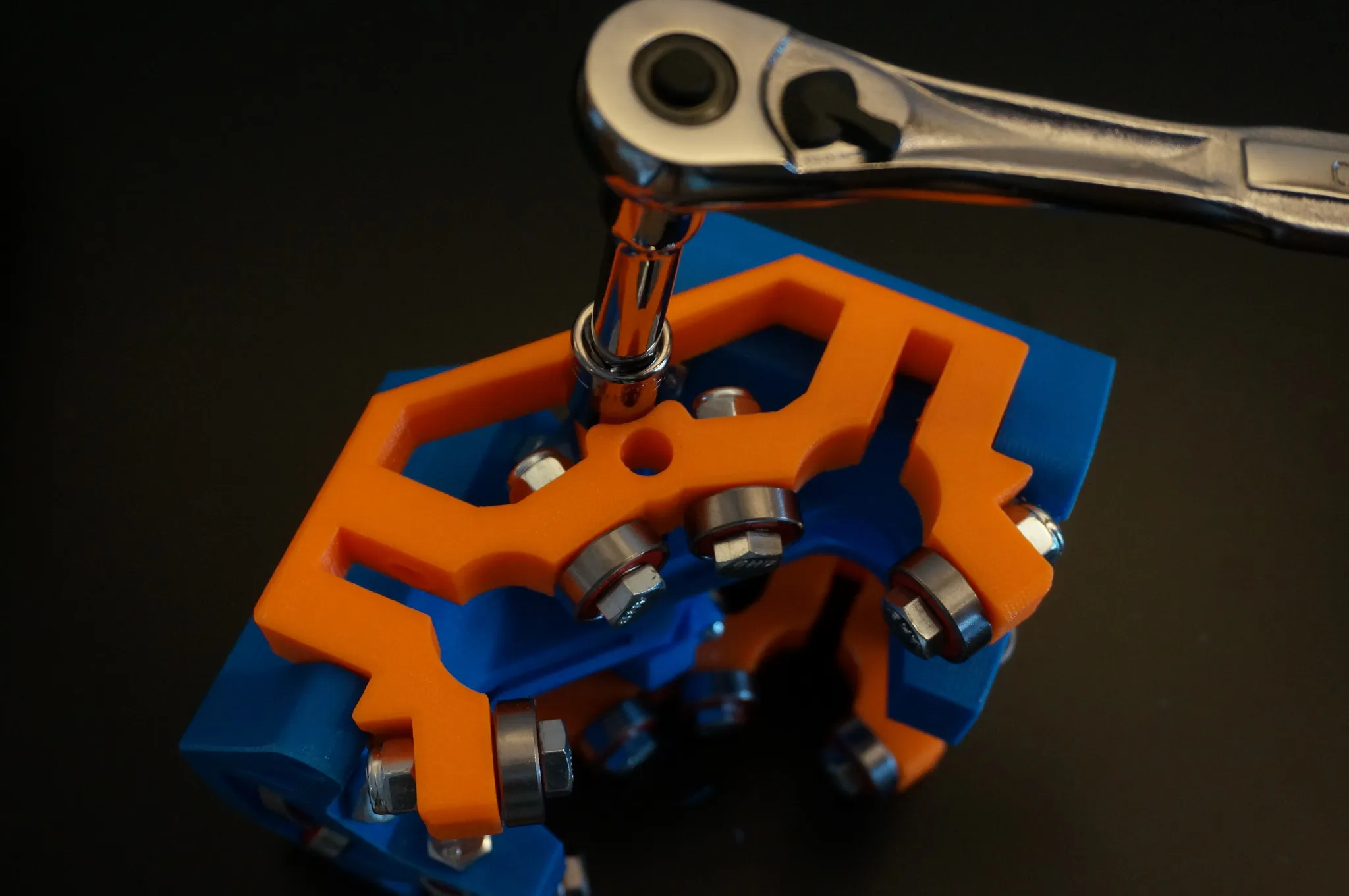
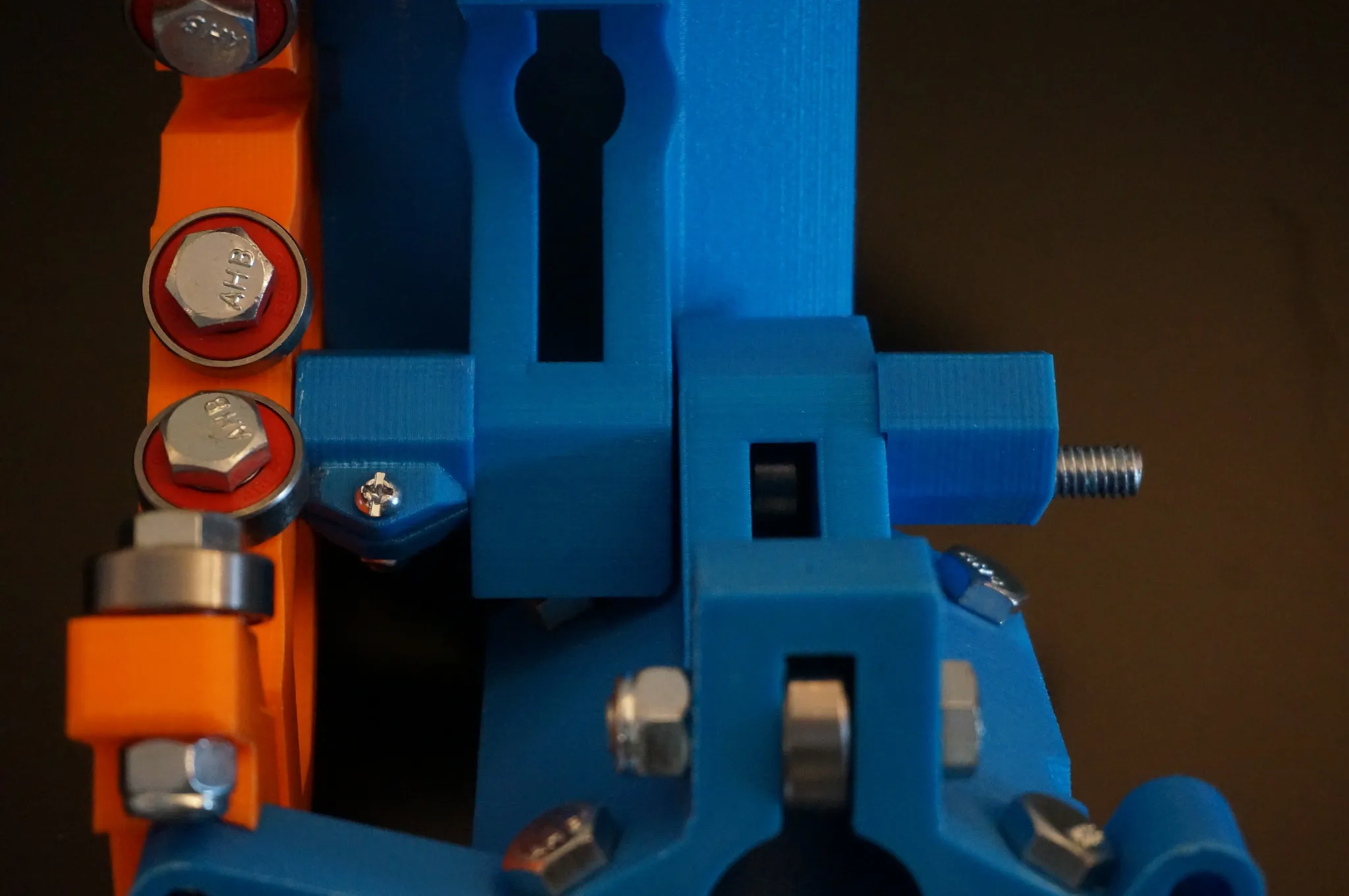
Test fit a piece of conduit and check to make sure it slides easily but is not loose. Adjust the bolt tightness if necessary.
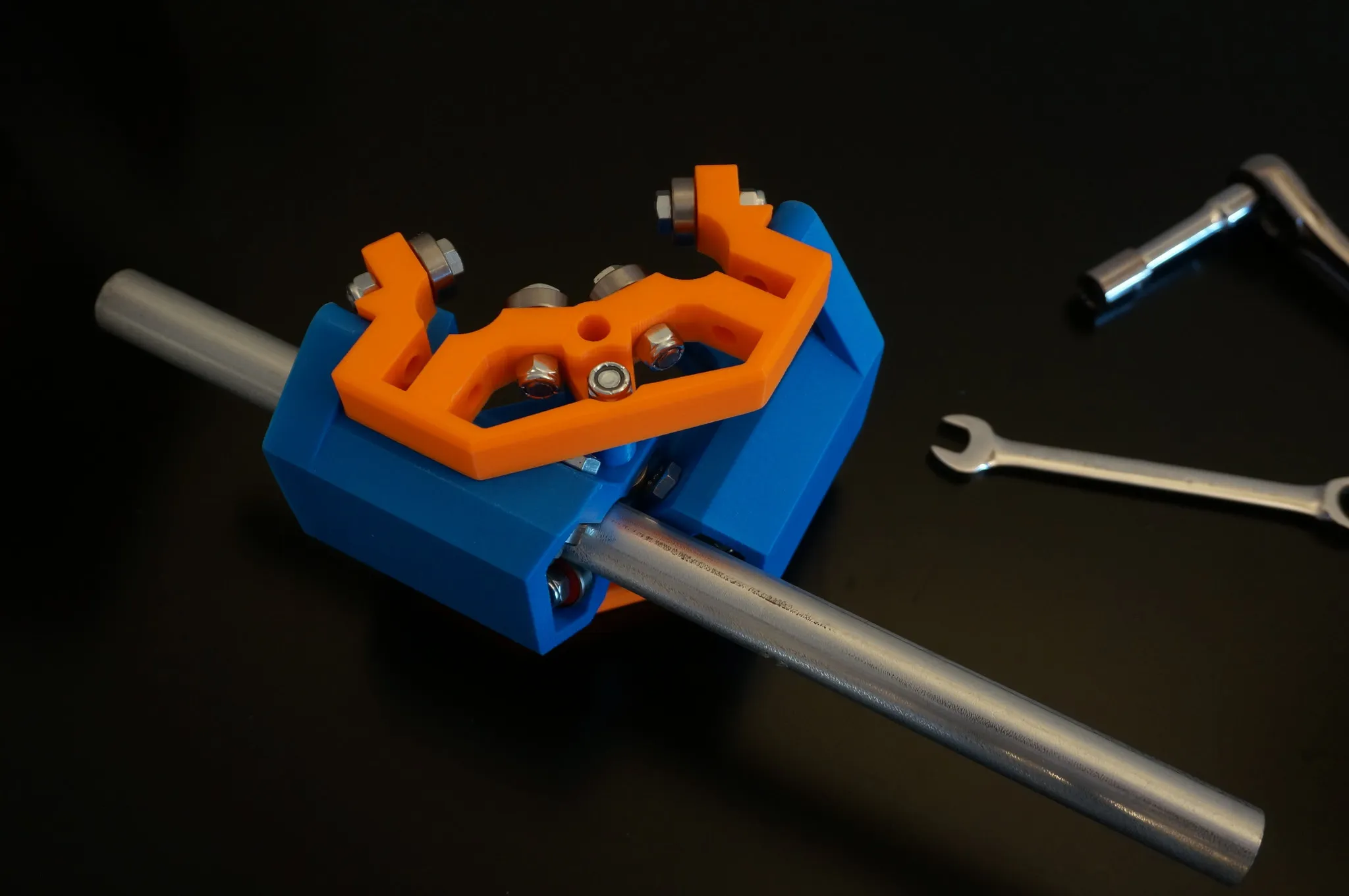
Bolt on the last four bearings.
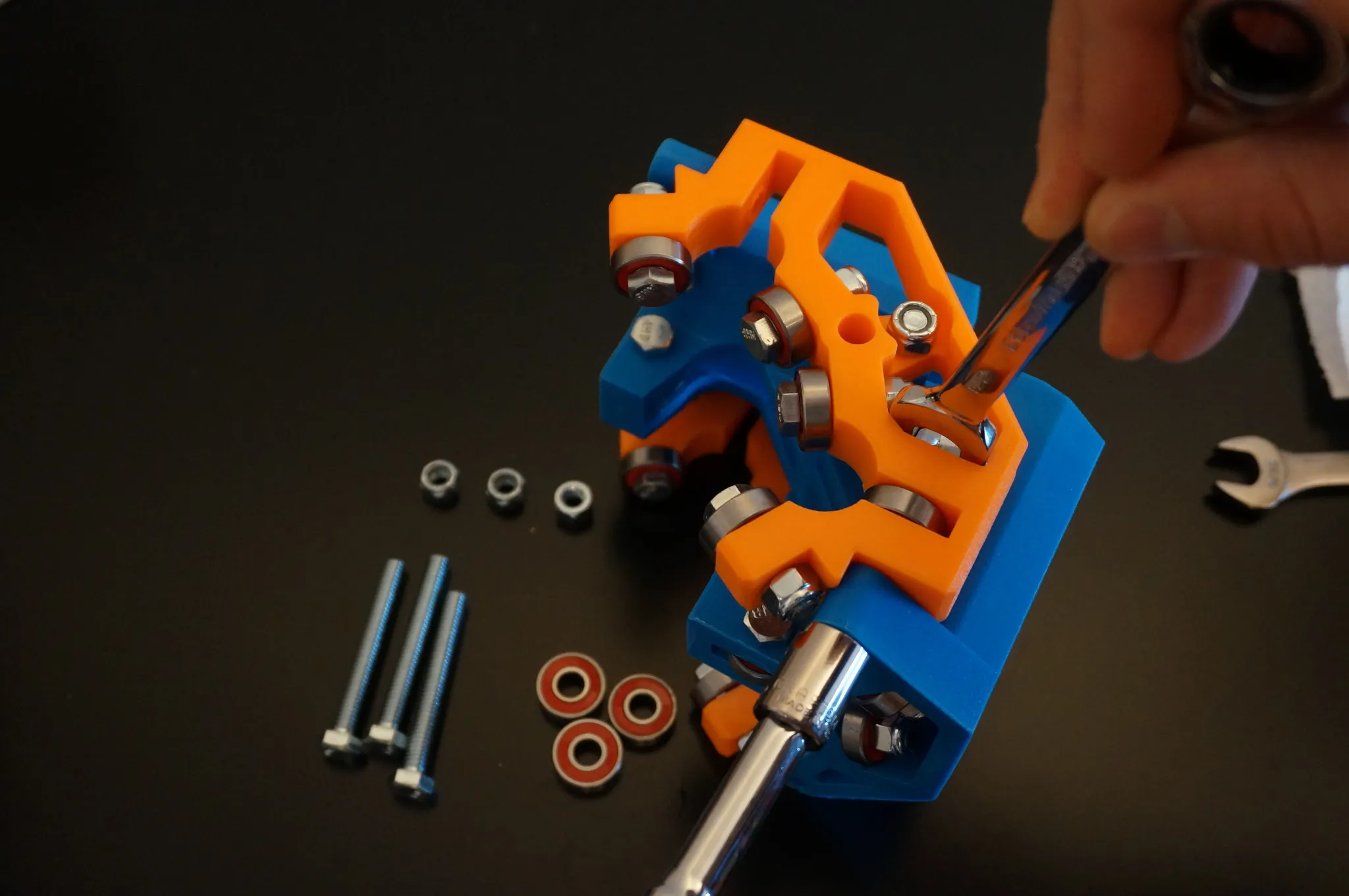
Check the tightness with a piece of conduit.
Z-Axis
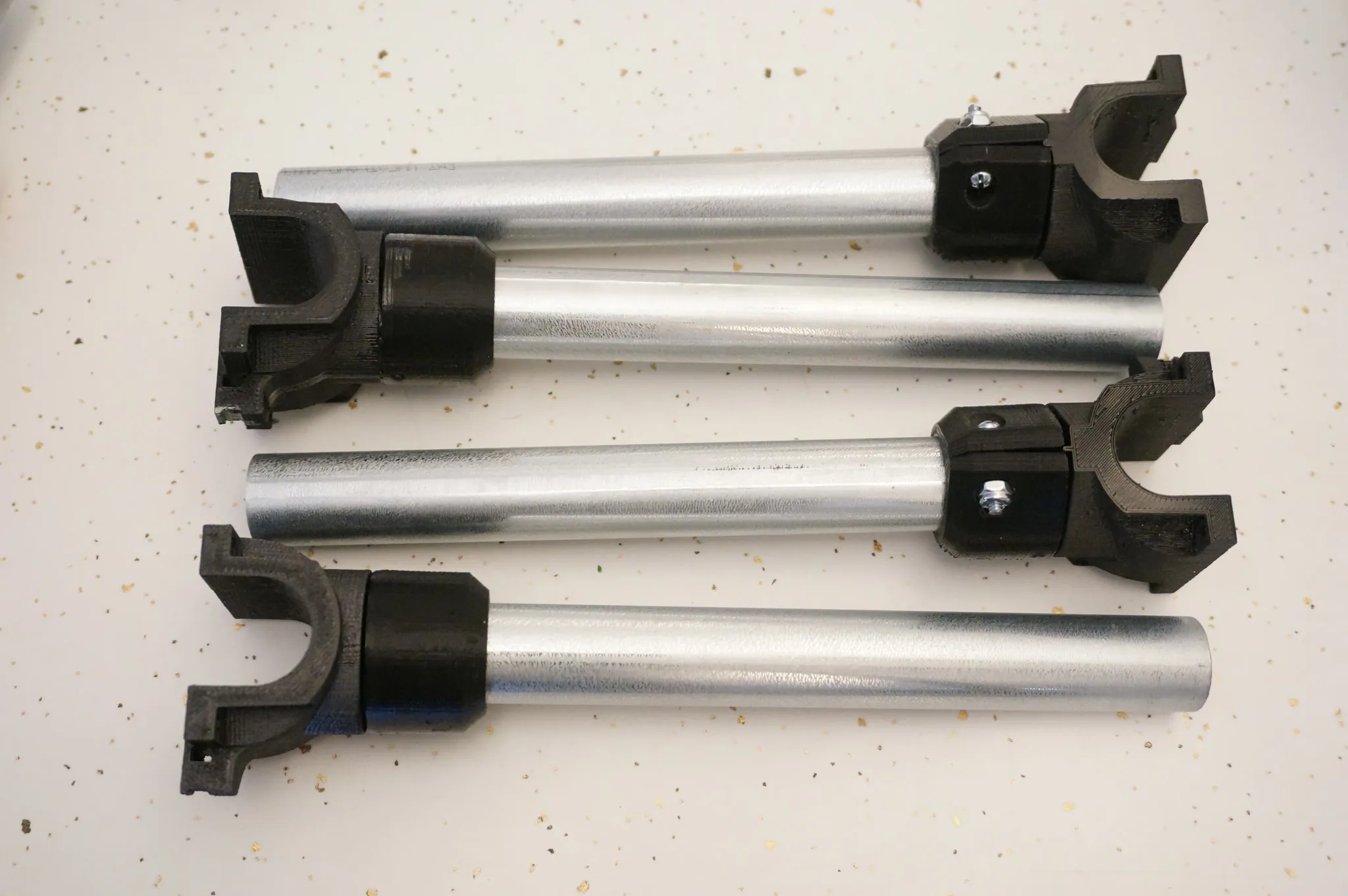
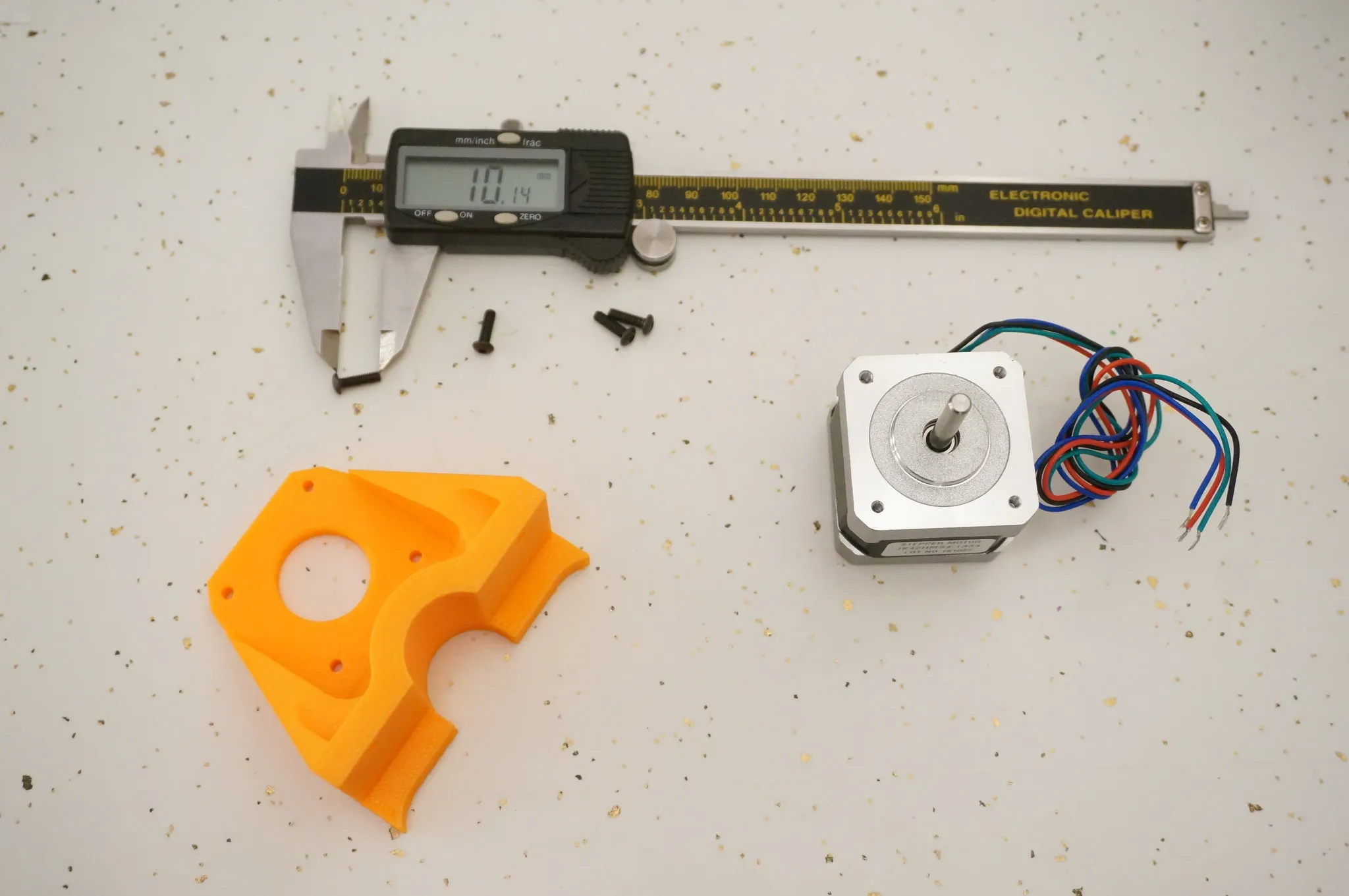
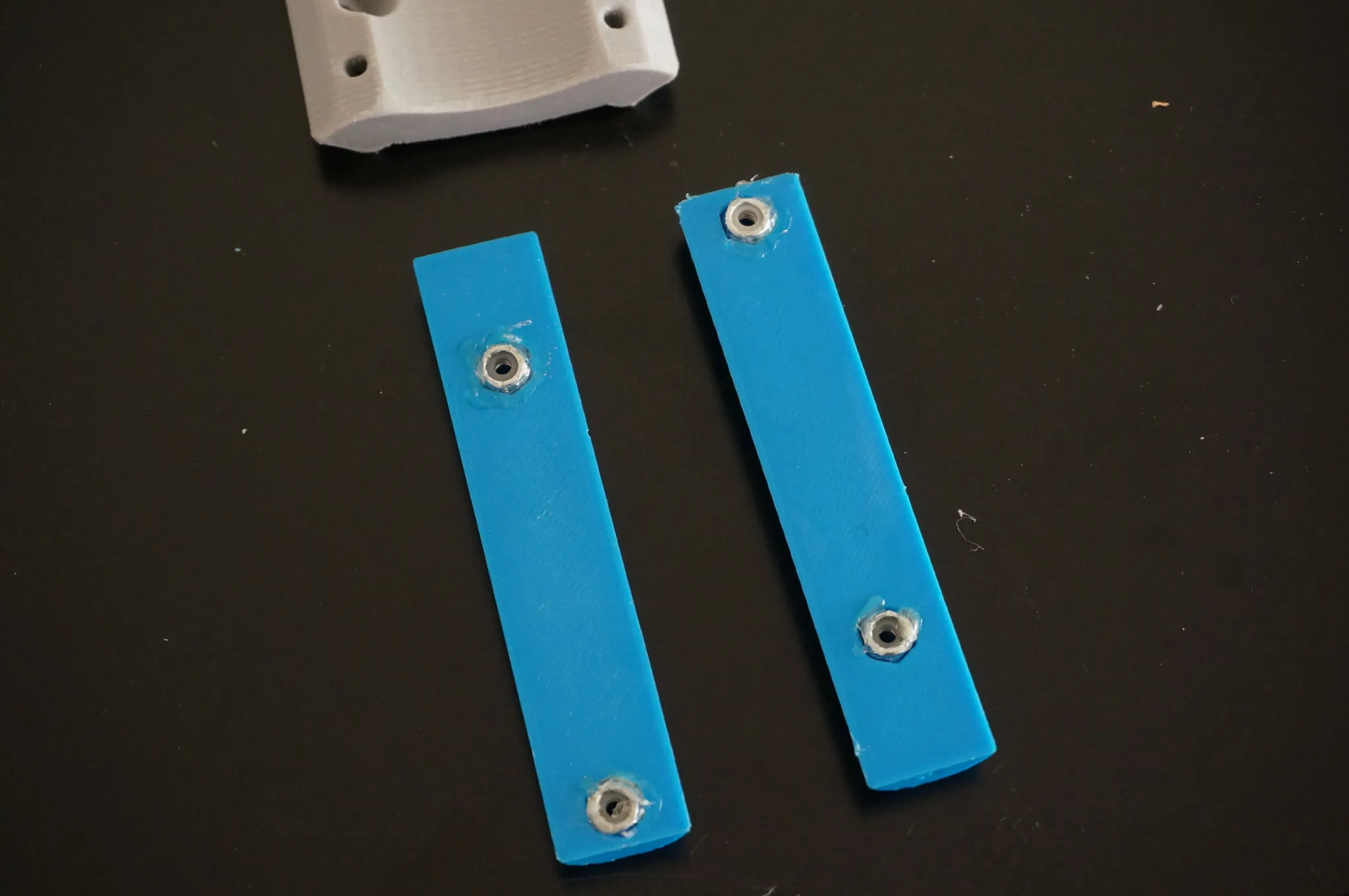
Here’s what you’ll need.
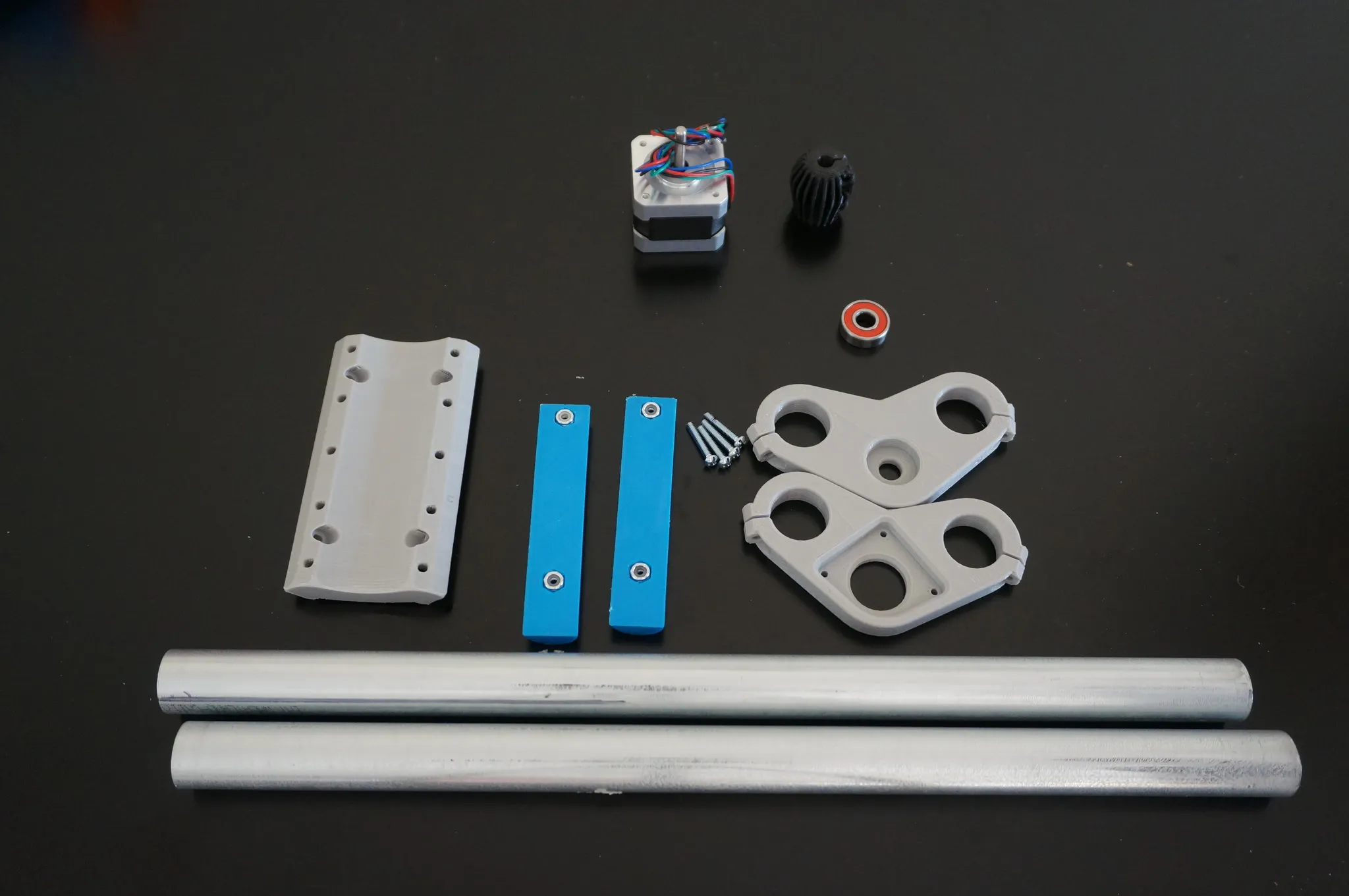
After fitting the nuts, fix them firmly in place with hot glue.
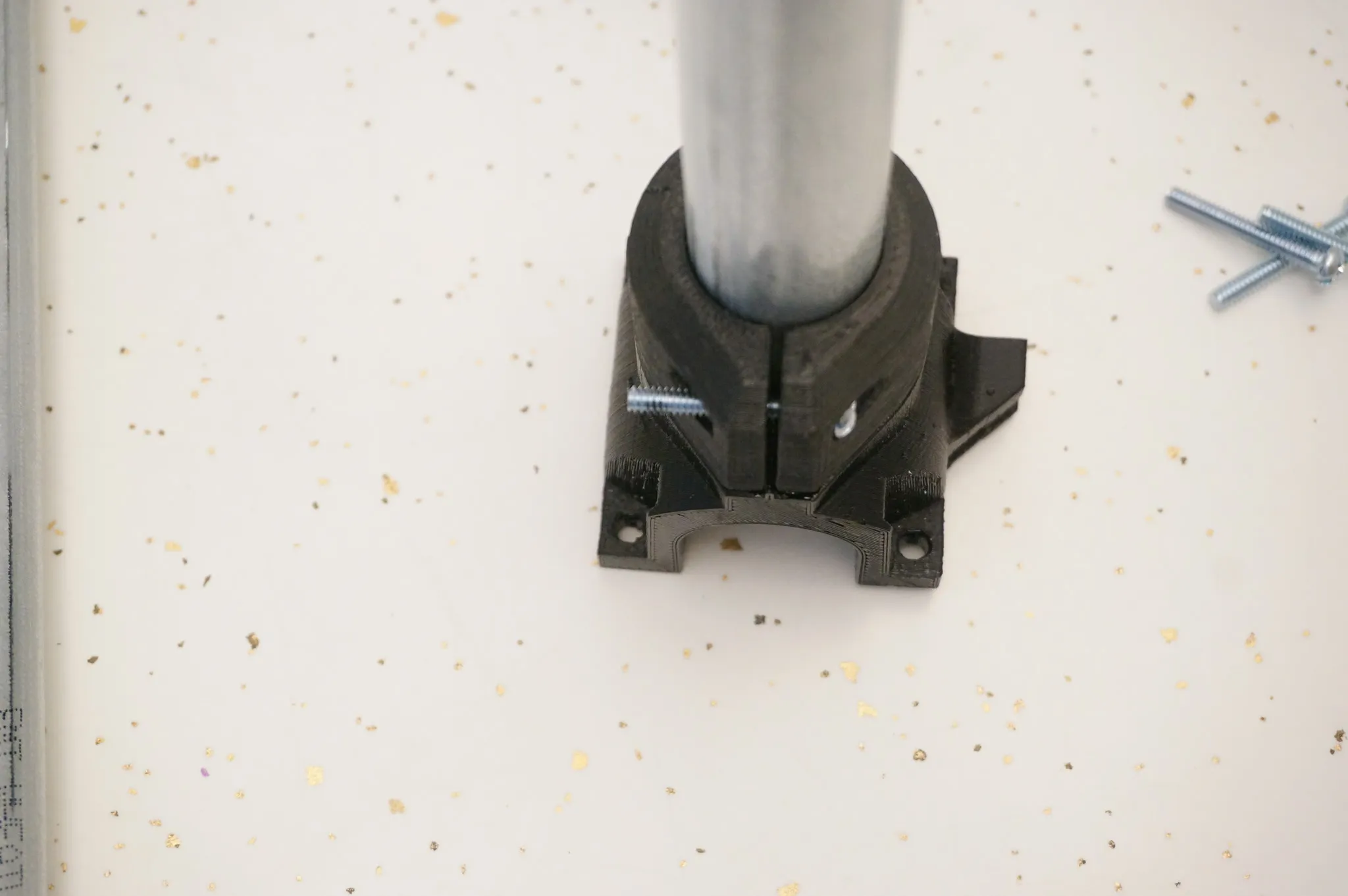
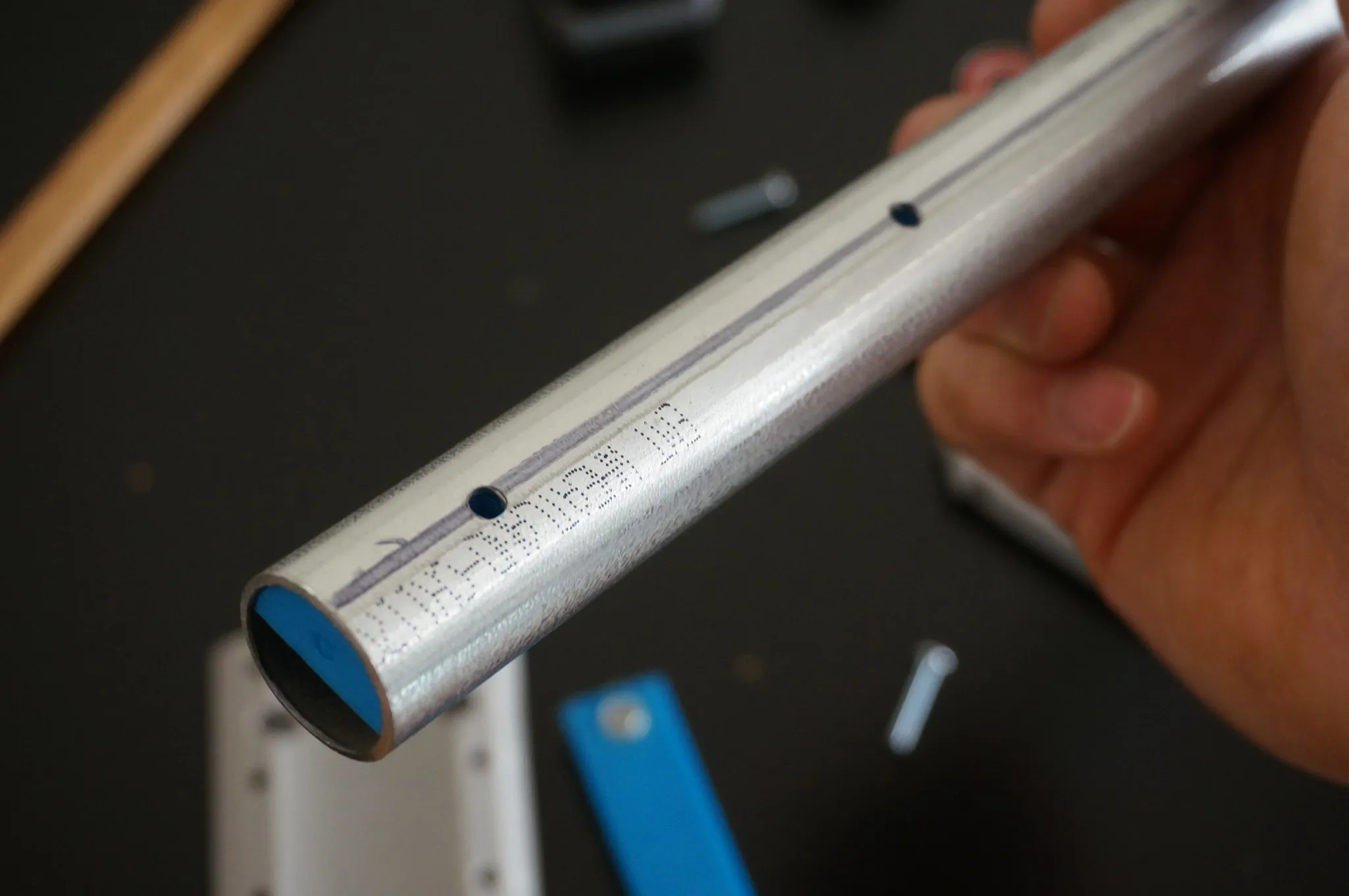
Drill the conduit and insert the bars holding the nuts. You may have to sand down the opening of the conduit if they don’t fit.
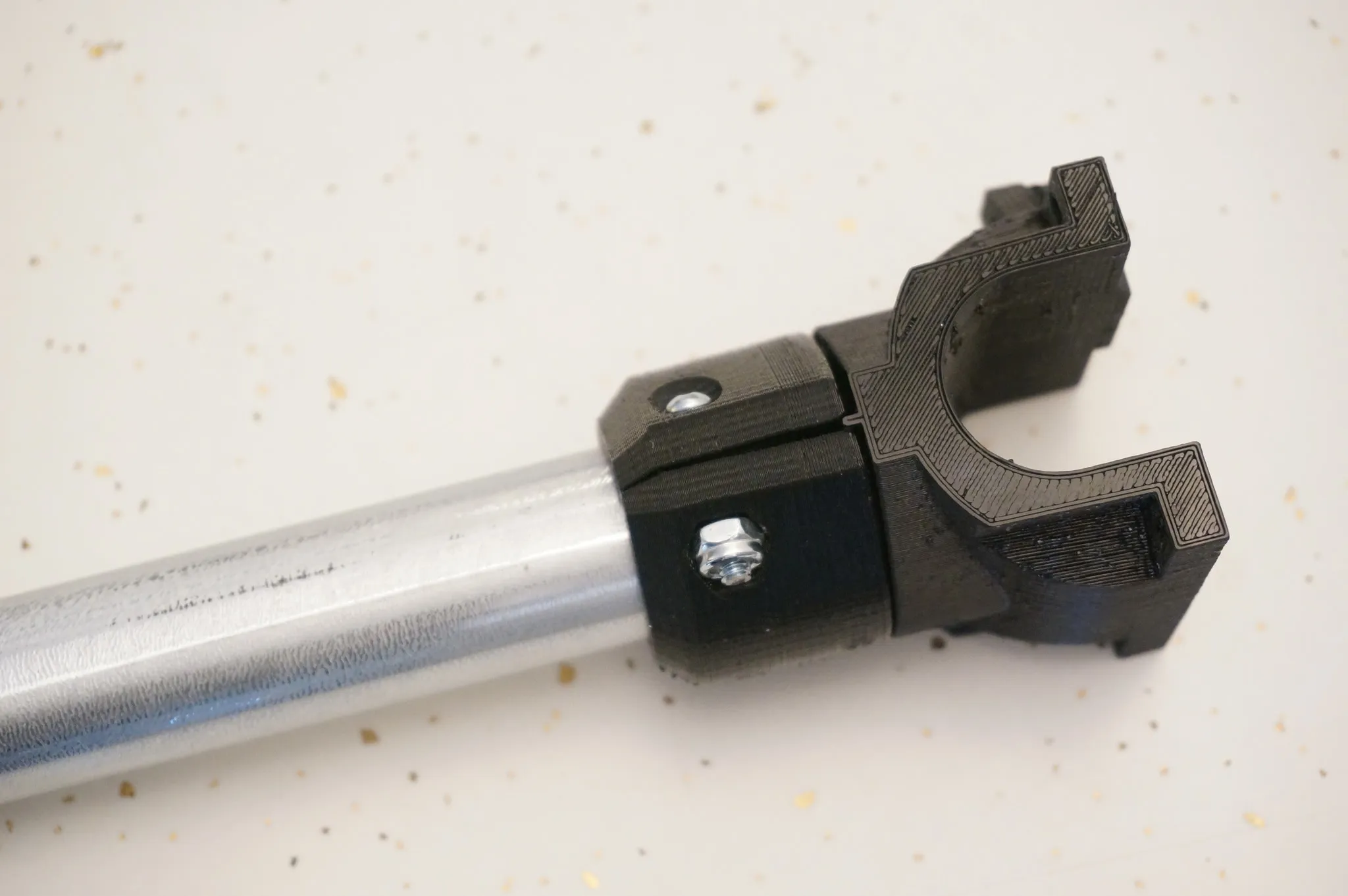
Bolt on the universal mount, loosely.
Bearing goes up.
These are 3x M3x10mm bolts.
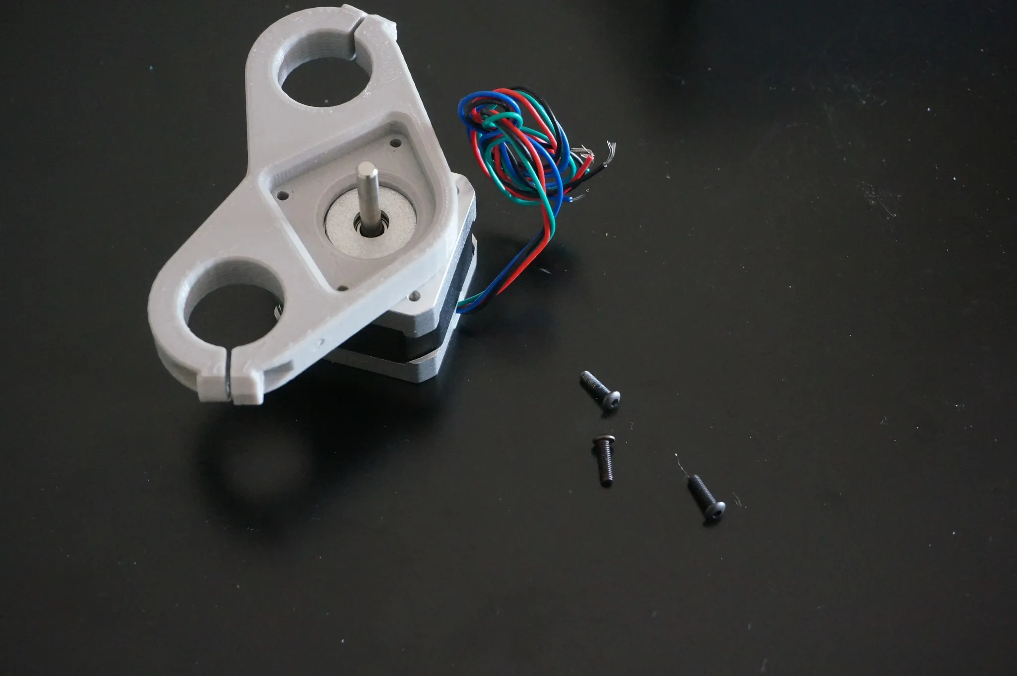
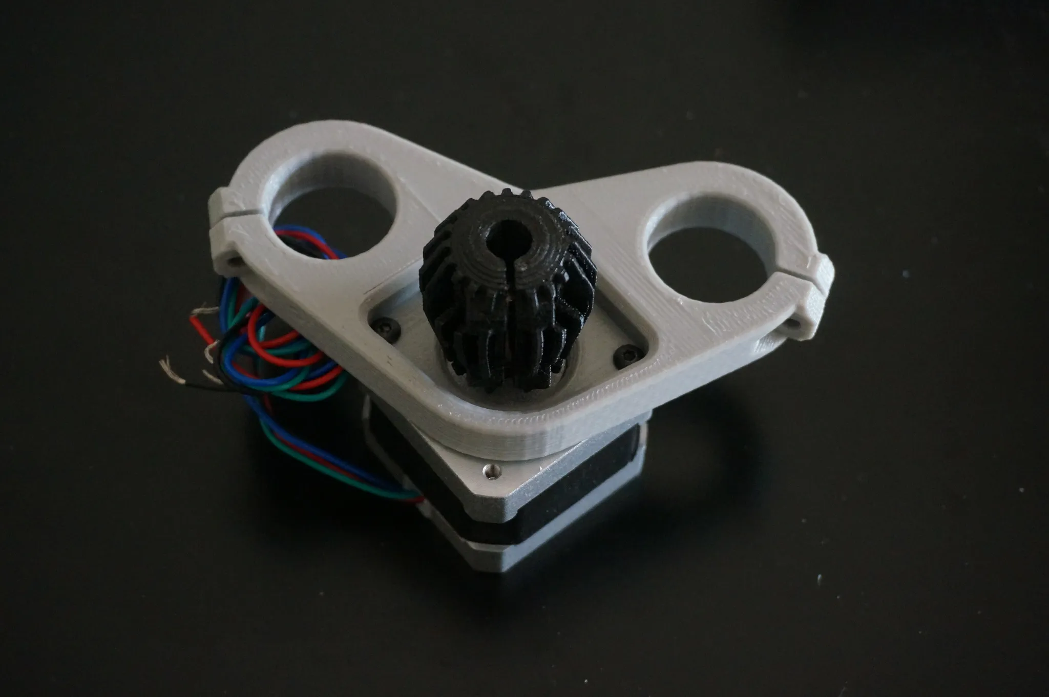
Install the stepper.
And the coupler.
Tighten the mount.
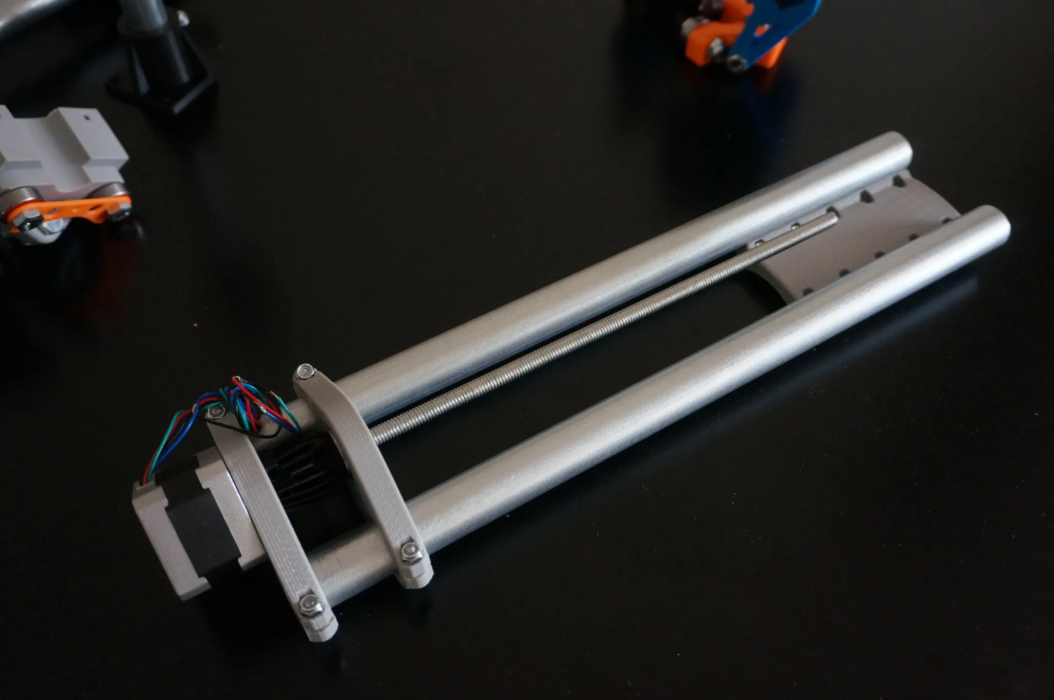
Install the threaded rod.
Final Assembly
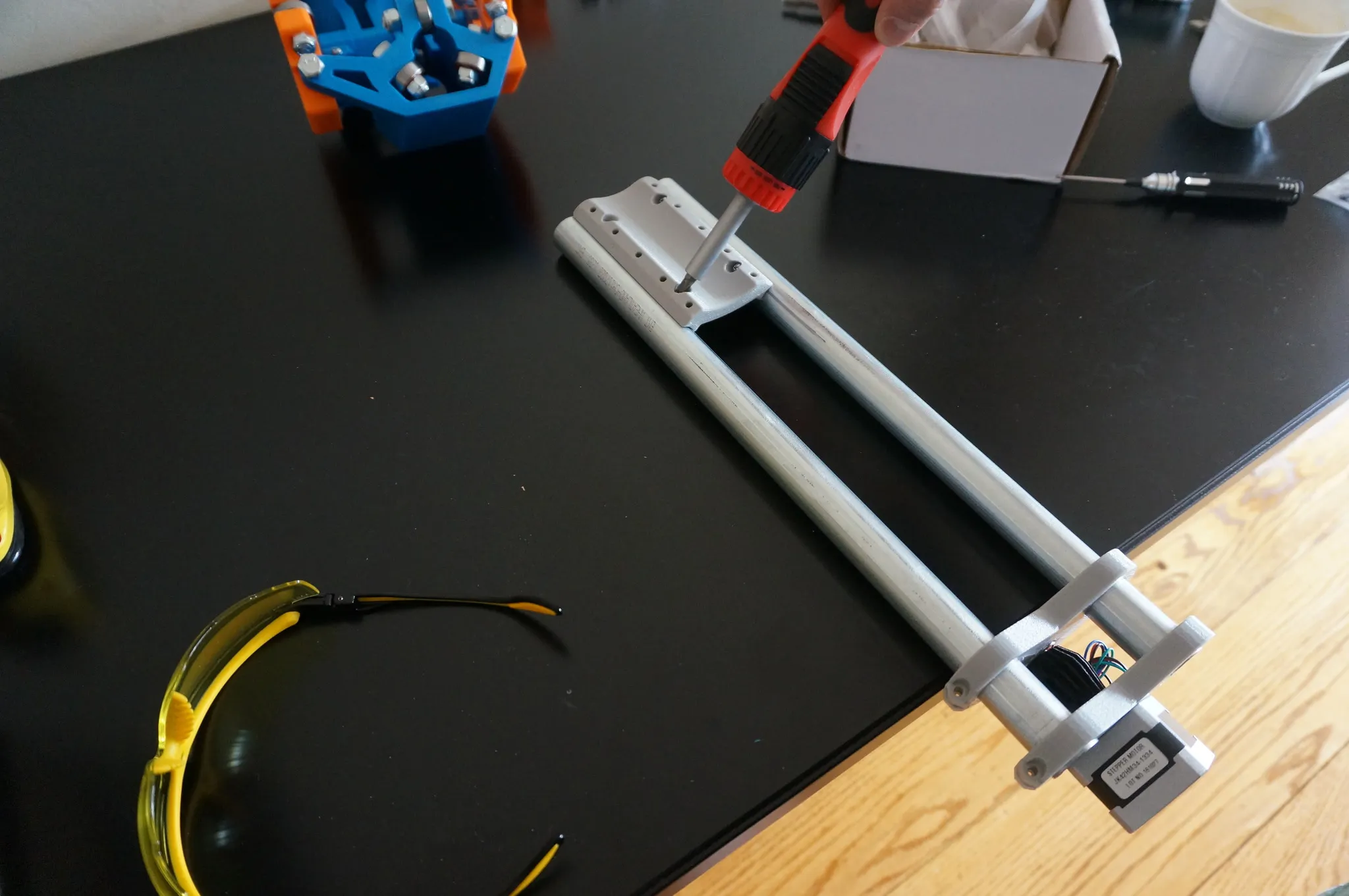
Mark, drill, and affix two corners.
Install the base of the legs.
Add the conduit rail.
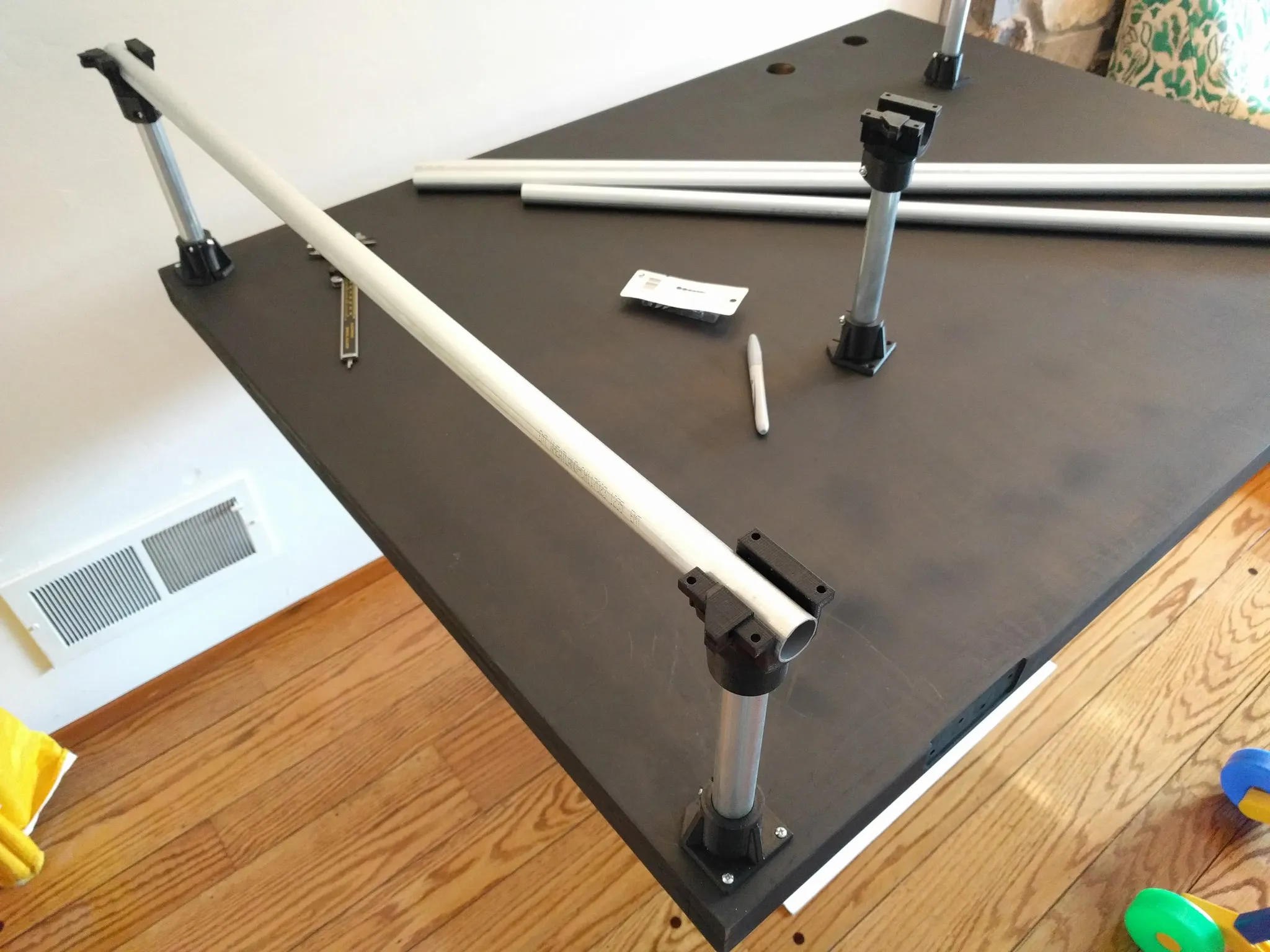
Then add the spacers.
And the conduit on the other side.
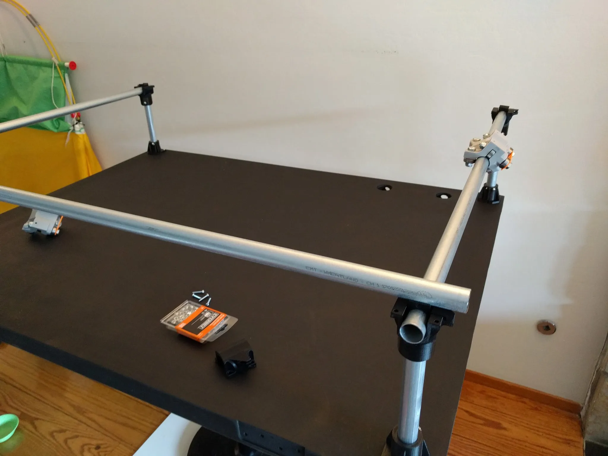
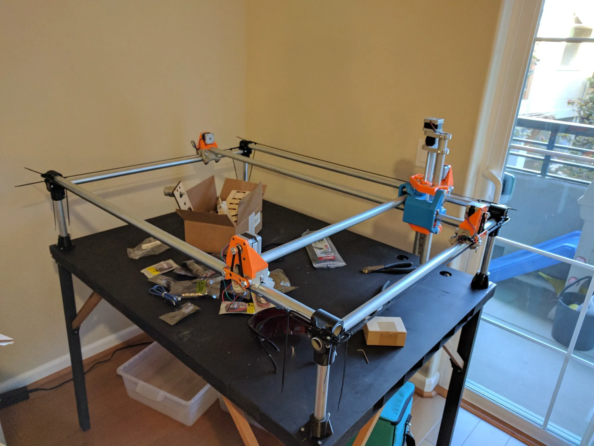
Be sure to install the carriages, then bolt on the top of the legs, loosely. With everything loosely attached now, measure diagonally and make sure everything is square. Drill and screw in the last two corners.
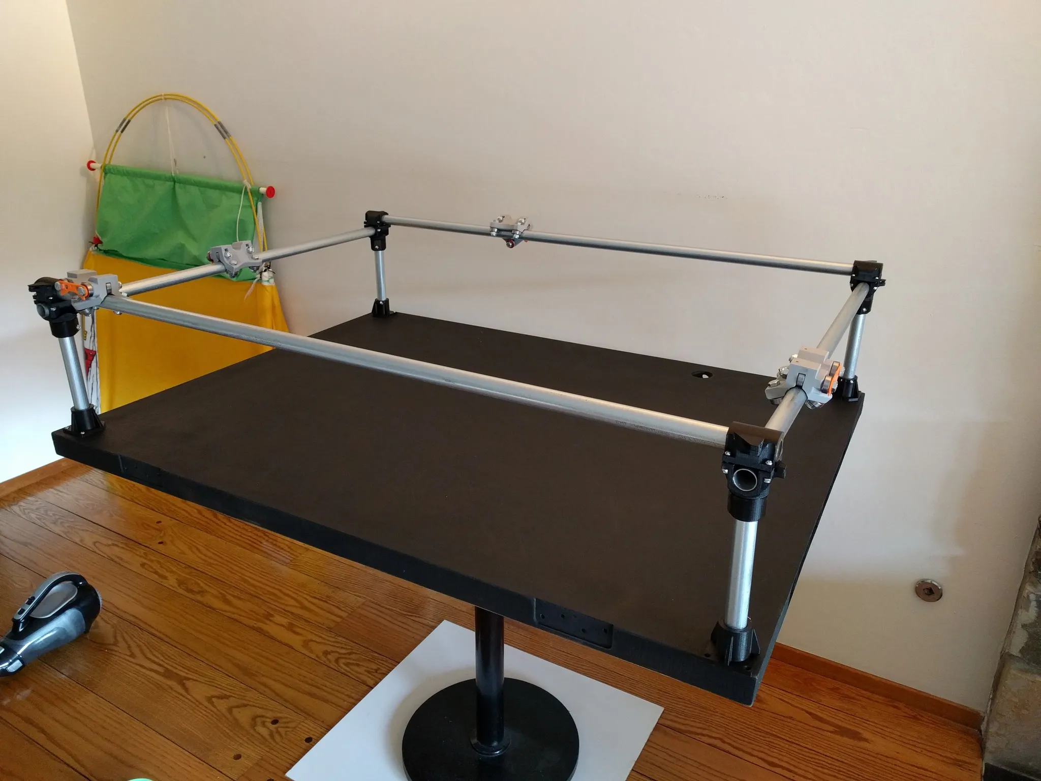
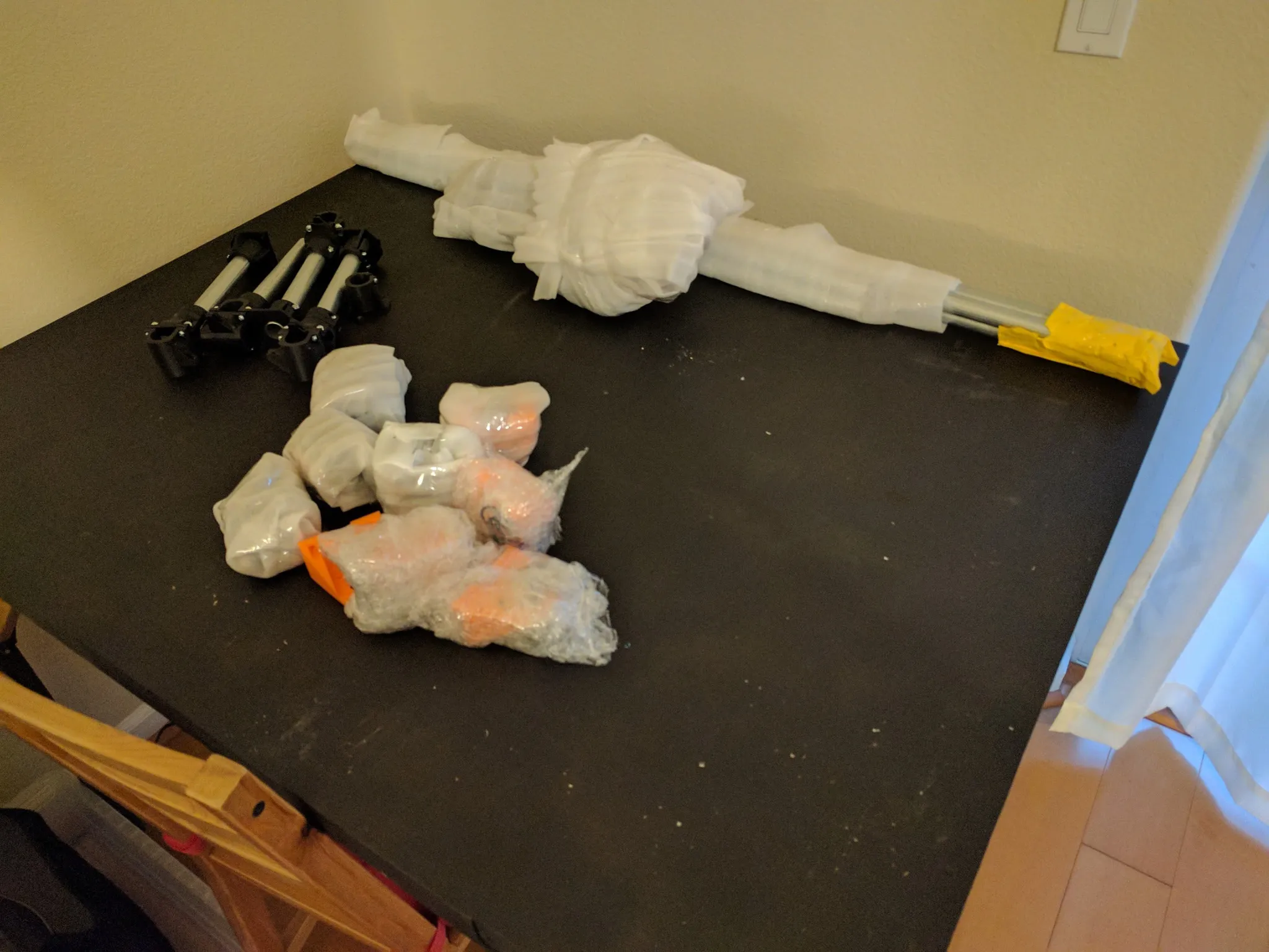
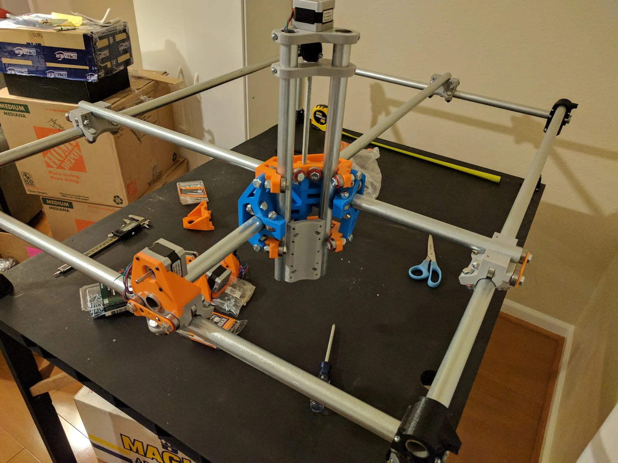
If you’re like me, now would be a good time to move (just kidding). Here we are in the new location.
Back to the build, insert the small nuts into the slots.
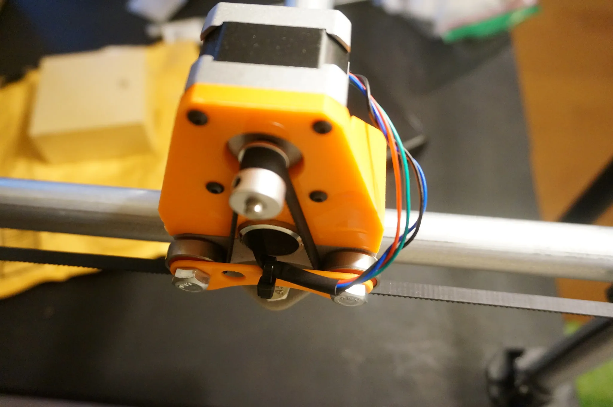
Slide the gantry into place and bolt the stepper motor mount onto each of the 4 carriages.
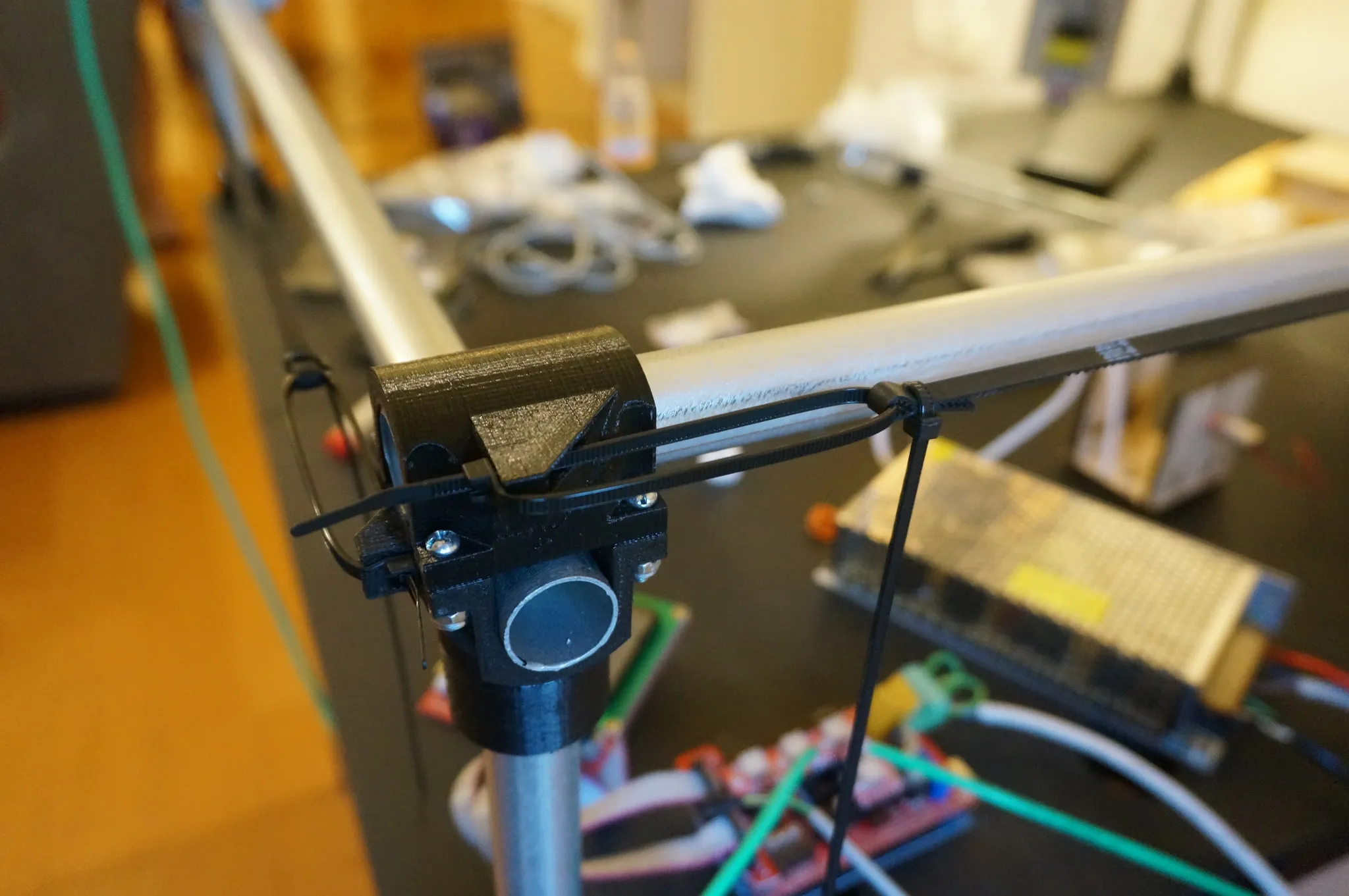
Here is how the belts are threaded.
Using the zip ties, affix the belts.
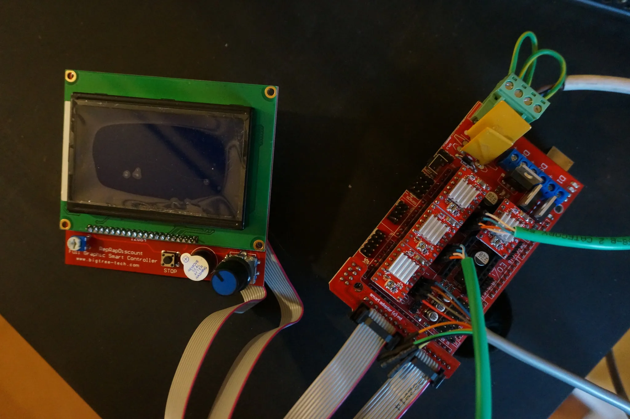
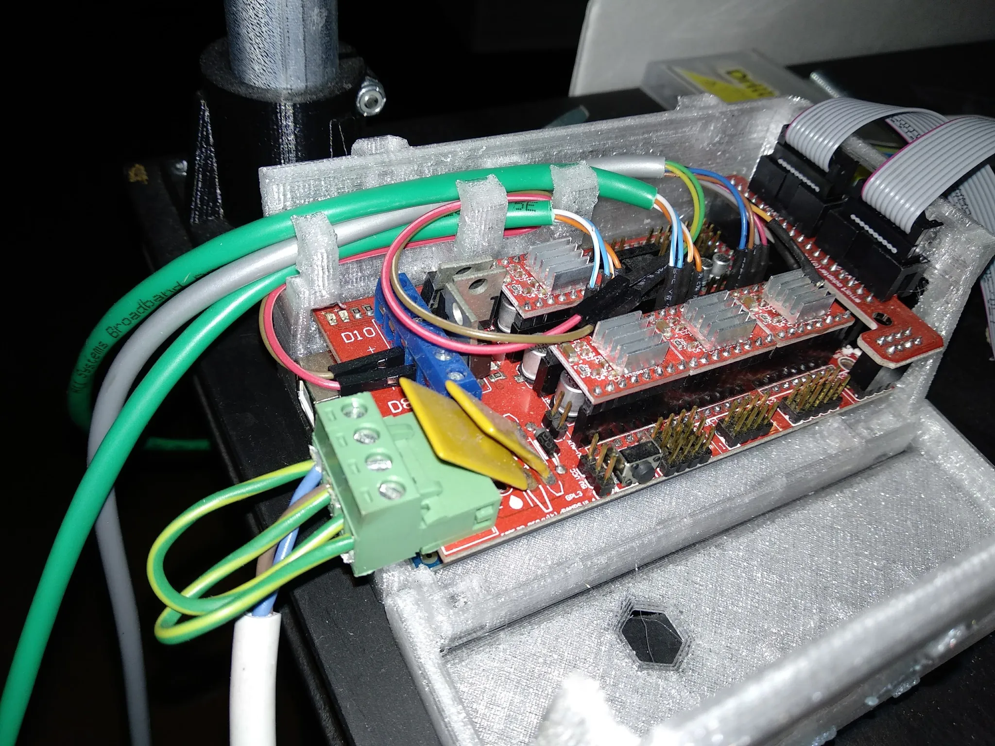
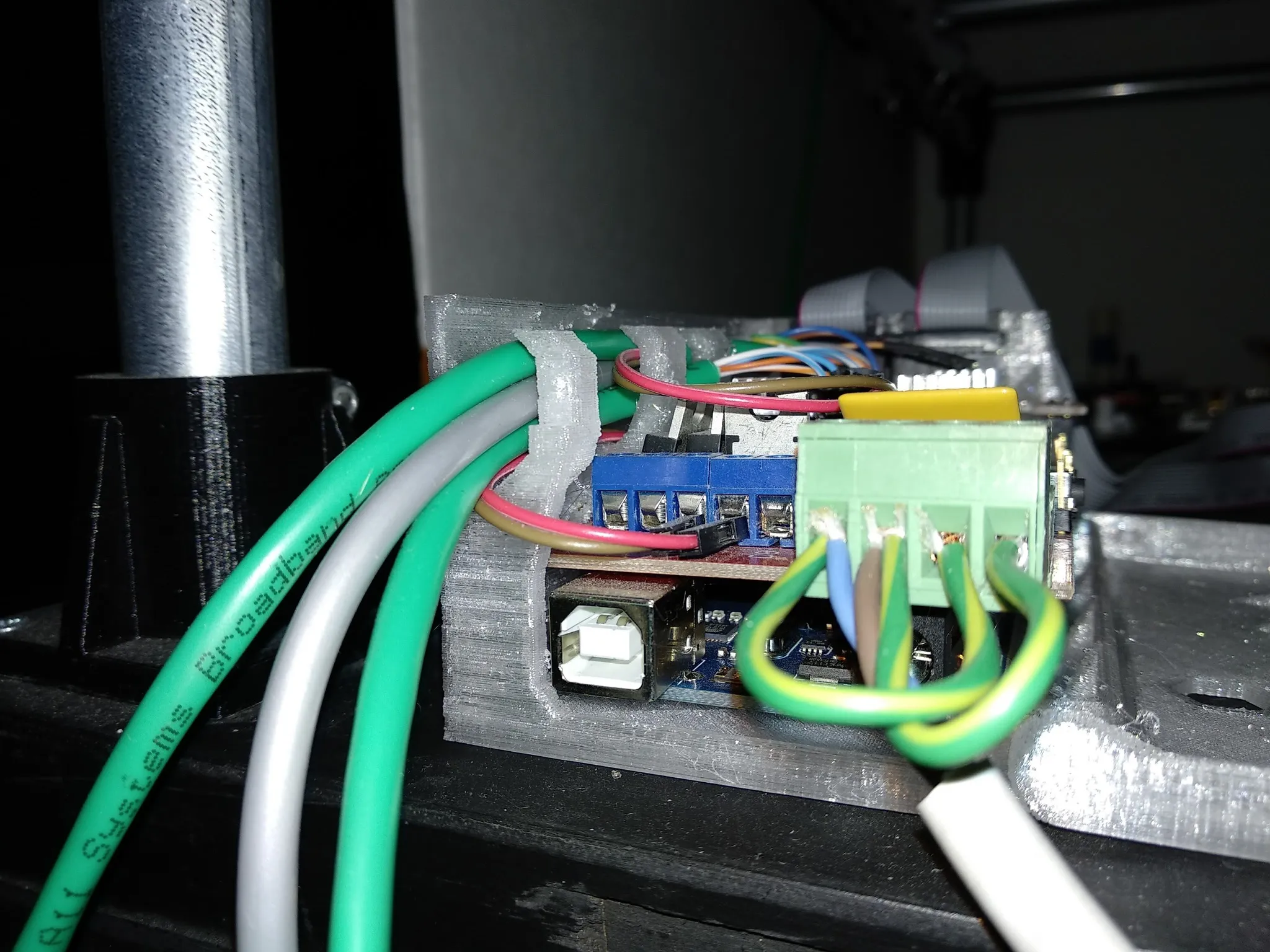
Electronics
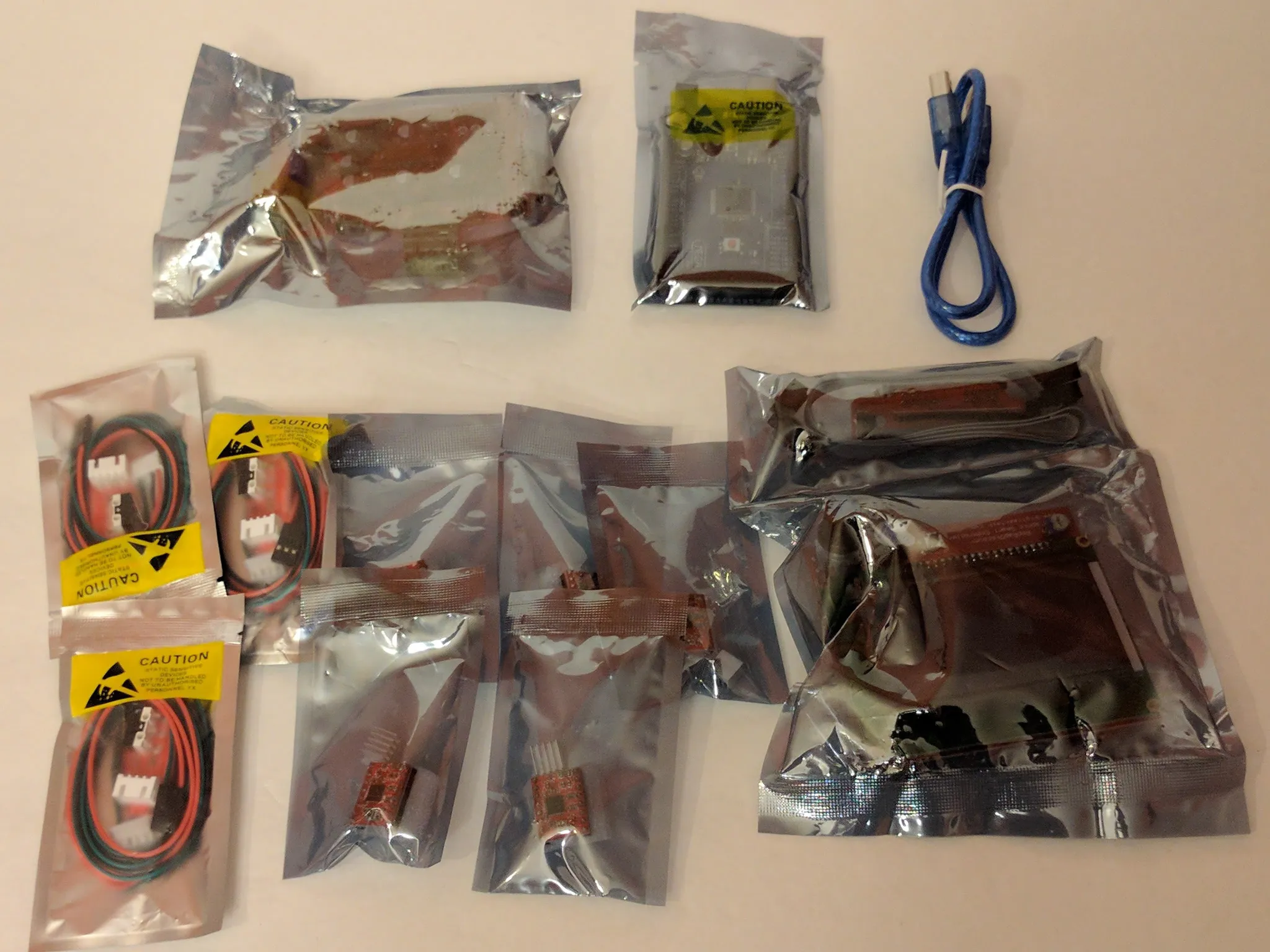
Here are all the electronics.
Let’s start with wiring.
Wiring
I used some old Ethernet cable (8 wire) and telephone cable (4 wire) to wire the stepper motors and the end effector plug.
For the series stepper motors, I wired them like this, using a 2.54mm pin header.
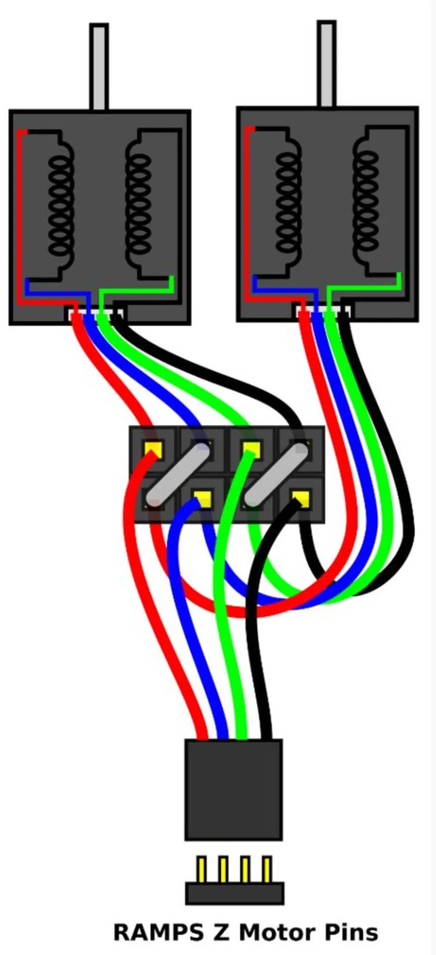
For the specific steppers listed in the BOM above, the pinout is:
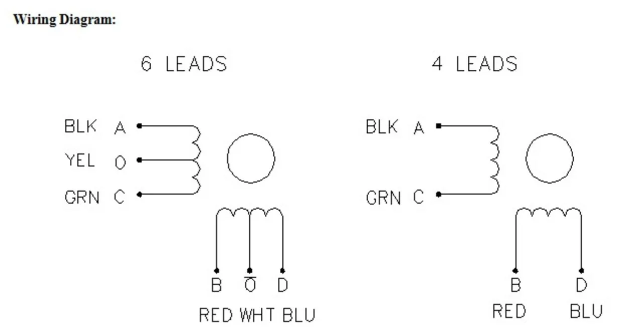
If one motor runs backwards, just try the position of any one of the wires in either pair.
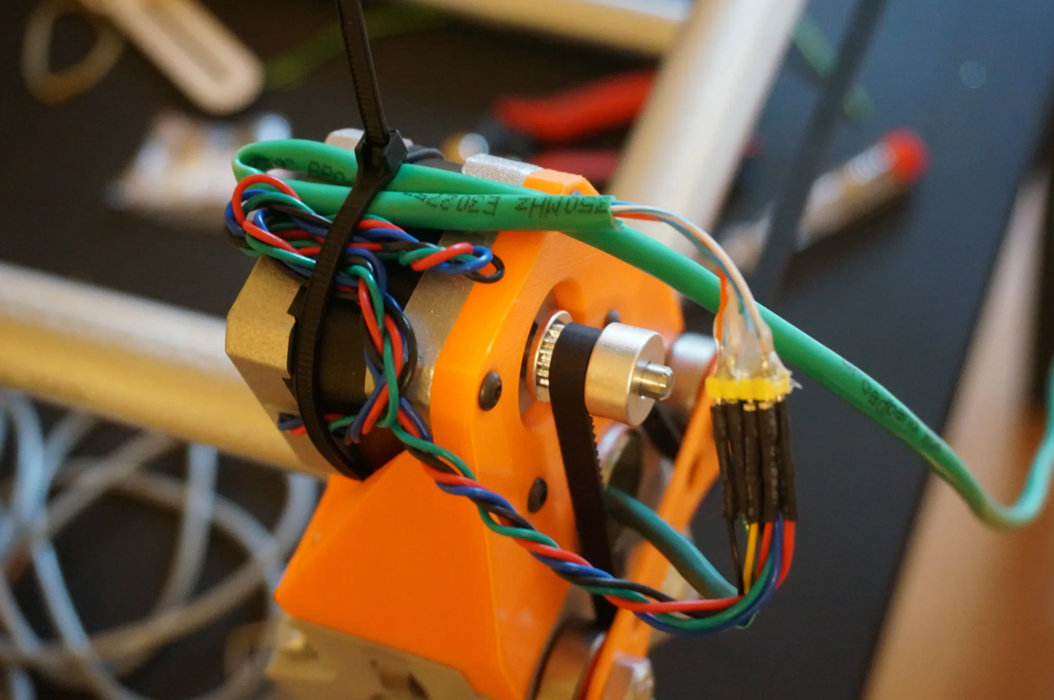
I soldered pin headers from standard 2 row 2.54mm pin headers.
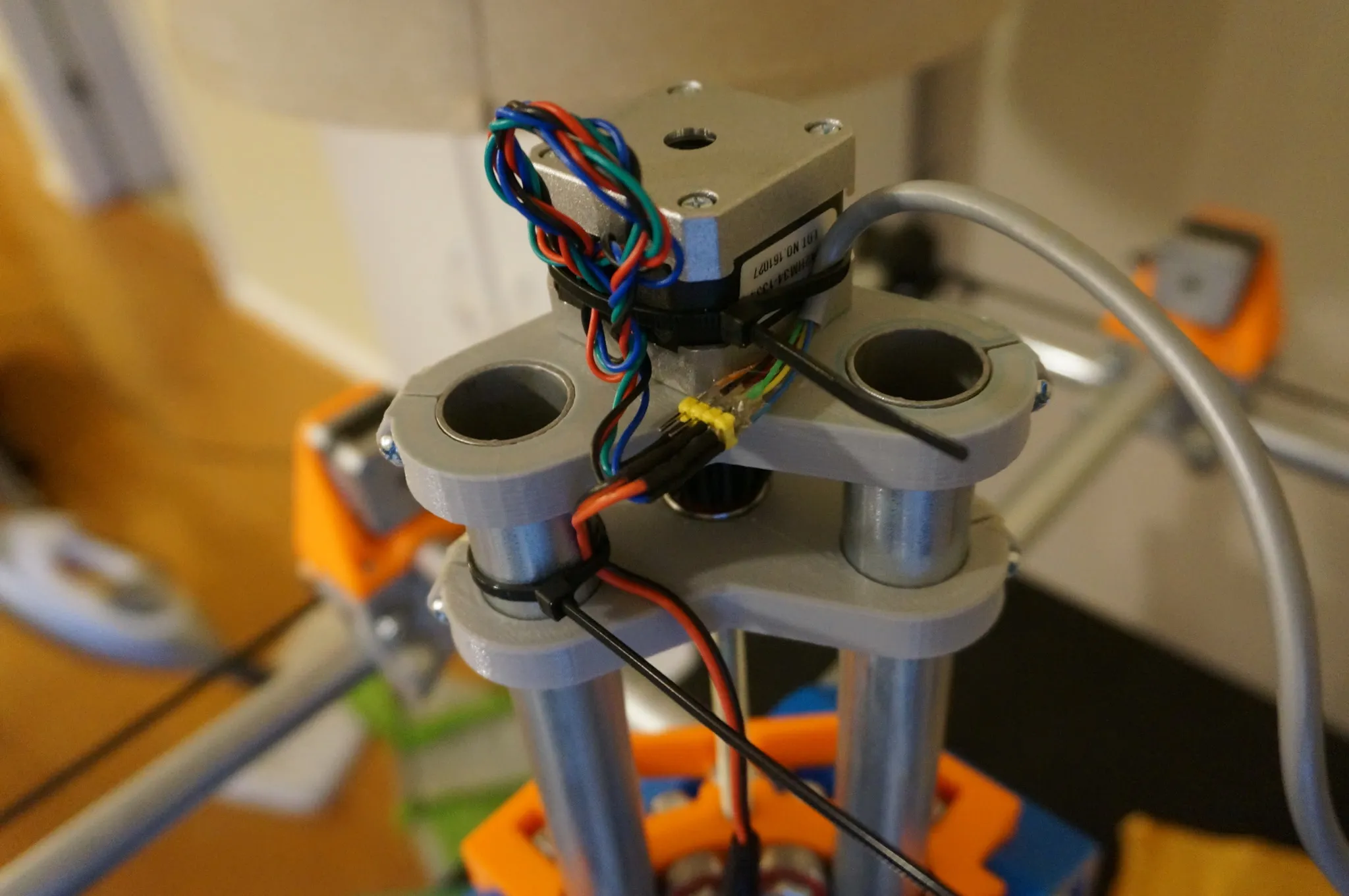
For the motors on the side opposite the controller, run the cables through the conduit.
RAMPS
I just followed Vicious1’s RAMPS setup guide here: https://www.vicious1.com/assembly/ramps-wiring/
Here is a full pinout of the RAMPS 1.4.
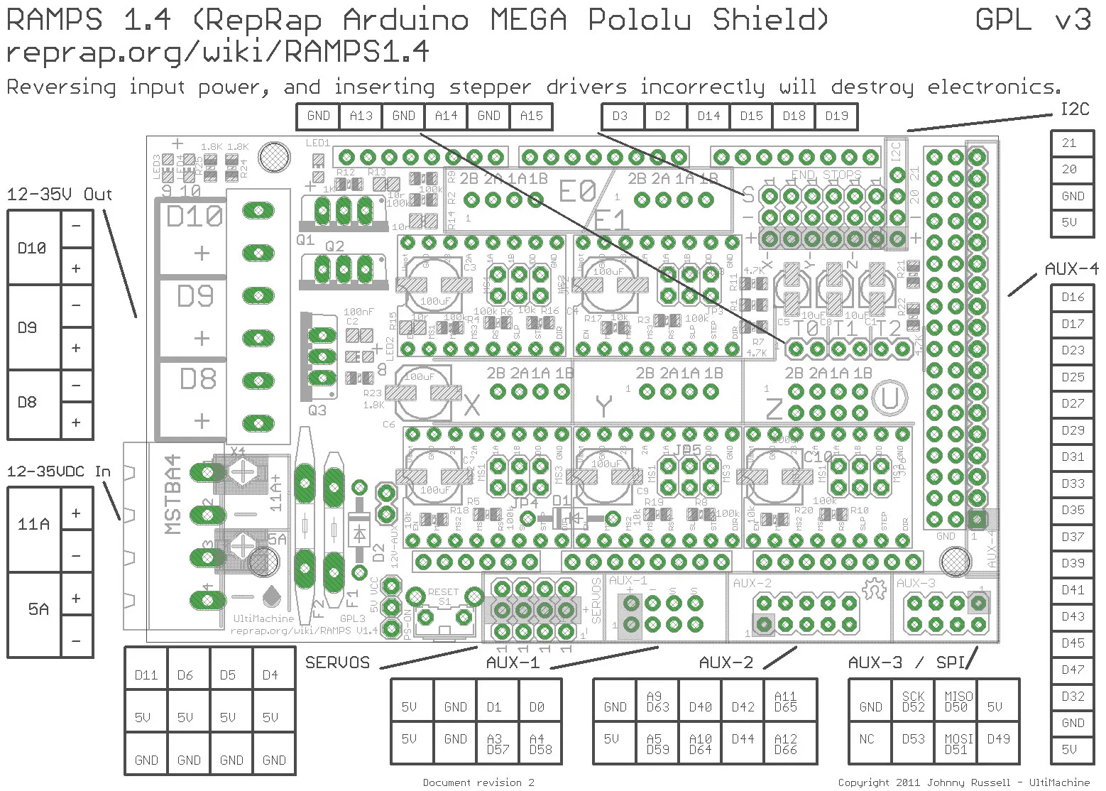
Push the RAMPS shield onto the Arduino Mega.
Fill all 3 headers below each motor driver slot you intend to use with 3 jumpers. This will give you the most resolution (microsteps) possible. They should look like this when populated:
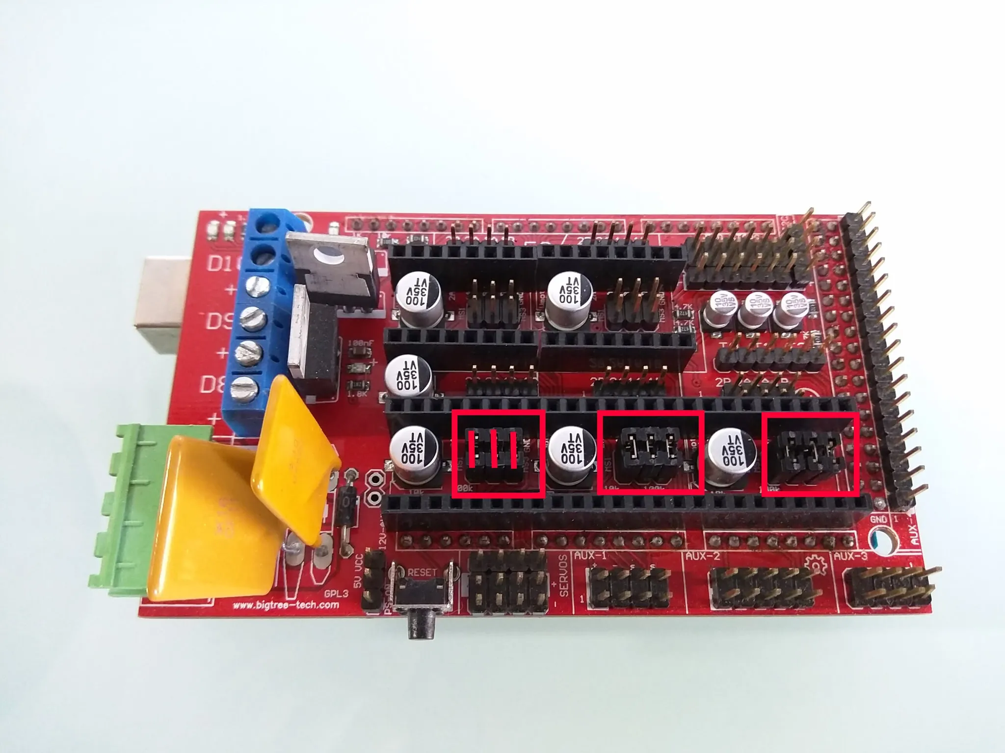 (Image credit Vicious1)
Be sure to read the pinouts for the motor driver you’re using and match them to the pinout on the RAMPS and install them.
Wire the power to your power supply.
And print a case, if you want.
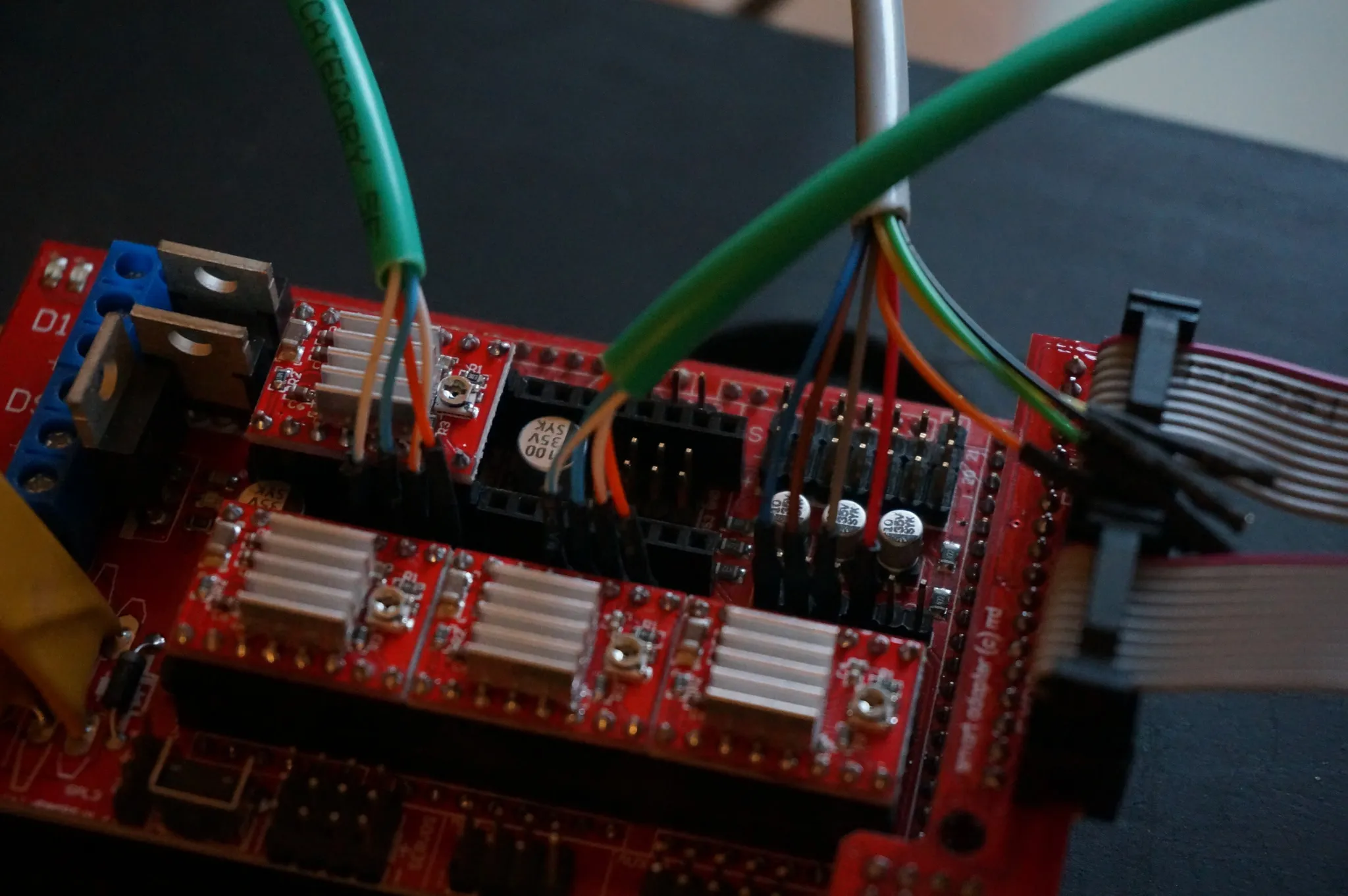
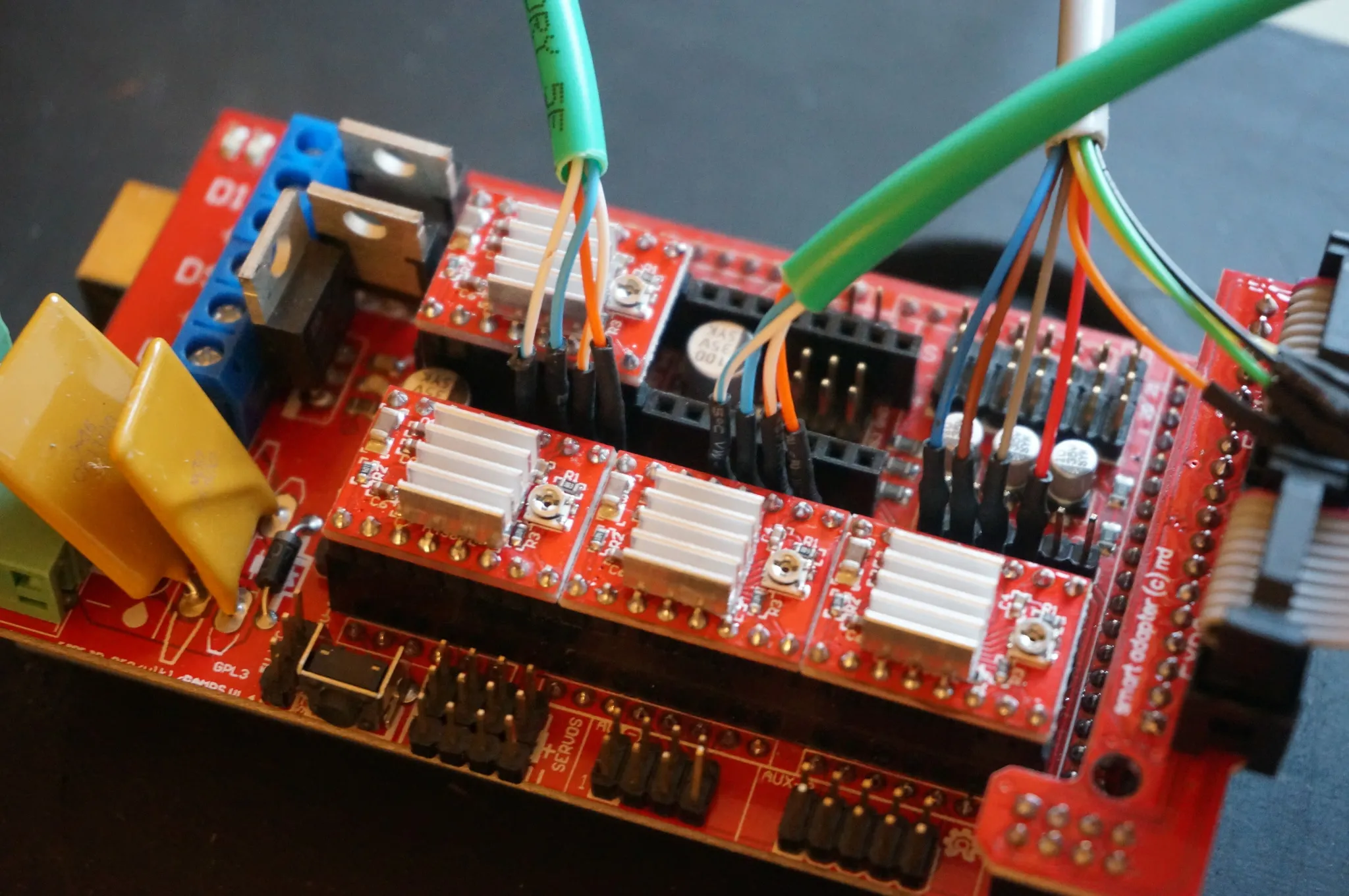
Plug in the motors.
Laser
If using a laser, we’ll want to connect these to the D9 terminals, Brown and Pink jumpers in these photos.
I used this 12V laser.
We’ll use the fan pin, D9 for the output, which is fine for our 12V laser, but don’t do this with a 5V laser.
The Marlin gcodes for fan control are:
M106 -- set fan power
M107 -- fan off
Full documentation for a different, 5V laser installation: https://www.dropbox.com/s/2a5t7iv0x2cax57/MPCNC-laser-add-on-walk-through-Rev2.0.pdf
Firmware
The latest version of Marlin for the MPCNC is available here: https://www.vicious1.com/marlin-firmware/; grab the RAMPS 1.4 version. I’m using https://www.vicious1.com/wp-content/uploads/2017/05/MPCNC813_GLCD_EB.zip with the extruder and heated bed enabled.
Feeds and Speeds
This is a list of tools mapped to feeds and speeds that I have found work well.
2.5W Diode Laser
| Action | Speed | Fan (laser pwm control) Speed |
|---|---|---|
| cutting | 150mm/sec | 255 |
| engraving | 300mm/sec | 255 |
Software
There are different tools that can be used to generate gcode for the MPCNC.
For CAM operations, cutting, and routing, use Fusion360.
For etching, try the http://nebarnix.com/img2gco/ website or Image2GCode.
Fusion360 Post Processor
For generating gcode from CAD. You can also import an SVG into a sketch in Fusion360, which is handy if you want to route a specific path very precisely.
Sketch your cut with Fusion360, then use the gcode post processor.
I cleaned up the MPCNC_Mill_Laser.cps post processor. You can grab my updated version from Dropbox or GitHub.
Open https://myhub.autodesk360.com/g/all_projects/active then open “Assets” -> “Cam Posts” and drag the .cps file in. Full directions: https://knowledge.autodesk.com/support/fusion-360/learn-explore/caas/sfdcarticles/sfdcarticles/How-to-install-a-cloud-post-in-Fusion-360.html
Follow the directions for use.
The V10 post processor here wasn’t working for me: https://www.dropbox.com/s/sreu7mhyh30o9j2/MPCNC_Fusion360_V10_SDcard.cps, but if you want to try it, here are the directions:
Inkscape Plugins
I installed Inkscape on my Mac with Homebrew, so that’s where I’ll copy the extensions. Your path may be different.
J Tech Photonics
The best Inkscape plugin, but it only works for outlines, not fills. I’ve found is the J Tech Photonics plugin: https://jtechphotonics.com/?page_id=1980
Download the correct version, http://www.jtechphotonics.com/Downloads/Inkscape/JTP_Laser_Tool_V2%20-%20inkscape%209_2%20version.zip in my case.
mkdir jtech && pushd jtech
unzip JTP_Laser_Tool_V2\ -\ inkscape\ 9_2\ version.zip
# copy the extension into the right folder, the target is in Inkscape under Preferences -> System -> User extensions
mv *.py /usr/local/Cellar/inkscape/0.92.2_1/share/inkscape/extensions/
mv *.inx /usr/local/Cellar/inkscape/0.92.2_1/share/inkscape/extensions/
popd
Import your DXF or SVG or whatever you want to cut.
When importing a DXF, don’t scale it, and if you don’t see the image, pick View -> Zoom -> Drawing.
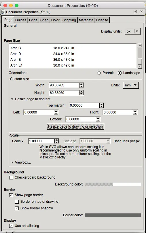
Under File -> Document Properties expand the Resize Page to Content... setting and click the Resize Page to Drawing or Selection button.
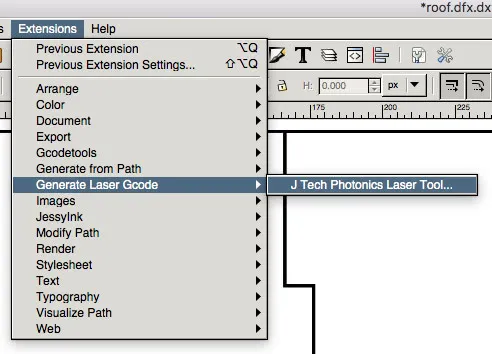
Under Extensions choose Generate Laser GCode and J Tech Photonics Laser Tool.
In the settings set:
Laser ON: M106
Laser OFF: M107
Travel Speed: 1000 (or whatever your machine can do)
Laser Speed: 300 (for engraving or 150 for cutting with a 2.5w laser)
Laser Power: 255 (max power)
Passes: 8 (at a minimum for plywood, 14 to be safe)
Pass Depth: 0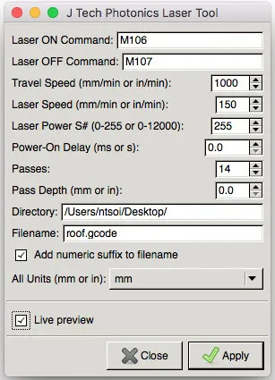
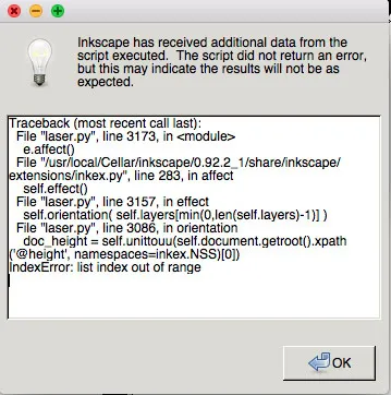
If you get an error like this, you’ll need to add a layer to your image:
The full guide for the plugin is here: https://jtechphotonics.com/?page_id=2012
Svg2G
This plugin didn’t work for me, I got the error: svg2g.py: error: no such option: --pen-up-angle, so the script probably needs to be debugged.
To install it, download the zip from GitHub and copy the contents of src/ into your Inkscape extension folder. When installed via homebrew on Mac, that would be something like this:
mv ~/Downloads/svg2g-master/src/* /usr/local/Cellar/inkscape/0.92.2_1/share/inkscape/extensions/Once installed, open an image and click File -> Save a Copy.
You’ll then see the options dialog for Svg2G.
I turned off registration, leave homing at 0,0.
SketchUp and SketchUCAM
Grab SketchUp Free here: https://www.sketchup.com/products/sketchup-free
Download SketchUCAM here: https://openbuilds.com/projectresources/sketchucam.1/
Change the settings for Marlin:
-
Open
tools,phlatboyz,options,machine optionsand setComments use Bracket or semicolonto false (we want to use semicolons). -
Open
tools,phlatboyz,options,feature optionsand setForce all gcodes on for Marlinto true.
Gcode Ripper
Haven’t tried this, but it looks pretty good if you have a Windows computer: http://www.scorchworks.com/Gcoderipper/gcoderipper.html#download
Estlcam
I haven’t tried this, but it seems to be a popular choice: http://www.estlcam.com/index.php
Image2GCode
For generating engraving gcode from an image.
Download Image2GCode version 1.1 here: https://www.dropbox.com/s/c31m6l3hmfneud5/3dpBurner-Image2Gcode-1.1.zip or the GitHub version here: https://github.com/Uthayne/3dpBurner-Image2Gcode
Gcode Simulation
Download GCodeSimulator[version].jar from https://www.thingiverse.com/thing:44286/#files
Run it with java -jar GCodeSimulator[version].jar.
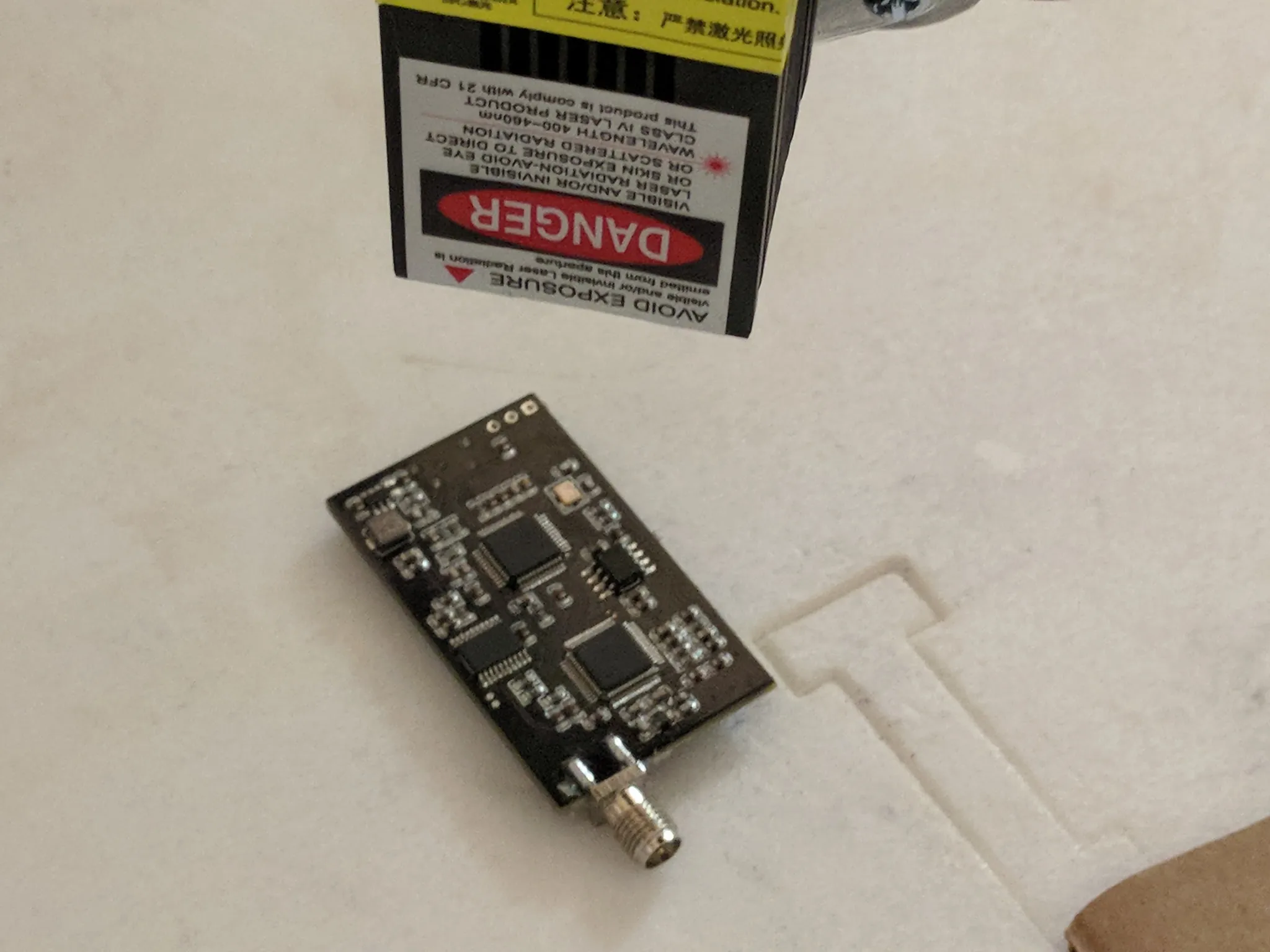
PCB Lasering
Open the layout in your PCB program; I’m using Eagle. Hide all but pads and the top layer. Show vias too, if you want those cut.
Then find the ratsnest button and hit it.
Hit print and under options pick only “Black” and “Solid”, choose the PDF printer.
Now, fire up your favorite image editor. I use Photoshop and import the PDF, turning up the resolution to max when prompted.
In Photoshop, change the main layer to have a white color overlay, insert a layer below it, fill it with black. Make your edits, like adding a little border.
Then send it to your cam program.