FlySky i6 Radio Setup and Hacking Guide
This is my unboxing, review and hacking guide for the Flysky FS-i6 2.4ghz radio transmitter.
I started this project thinking I could easily use the 4-in-1 DIY transmitter module in the radio, but this turned out to not be the case. Instead, I’ve start working on porting OpenTX with serial support for the 4-in-1 DIY transmitter module. Devs, help me out here! https://github.com/nathantsoi/opentx/tree/target/fs-i6
Unboxing
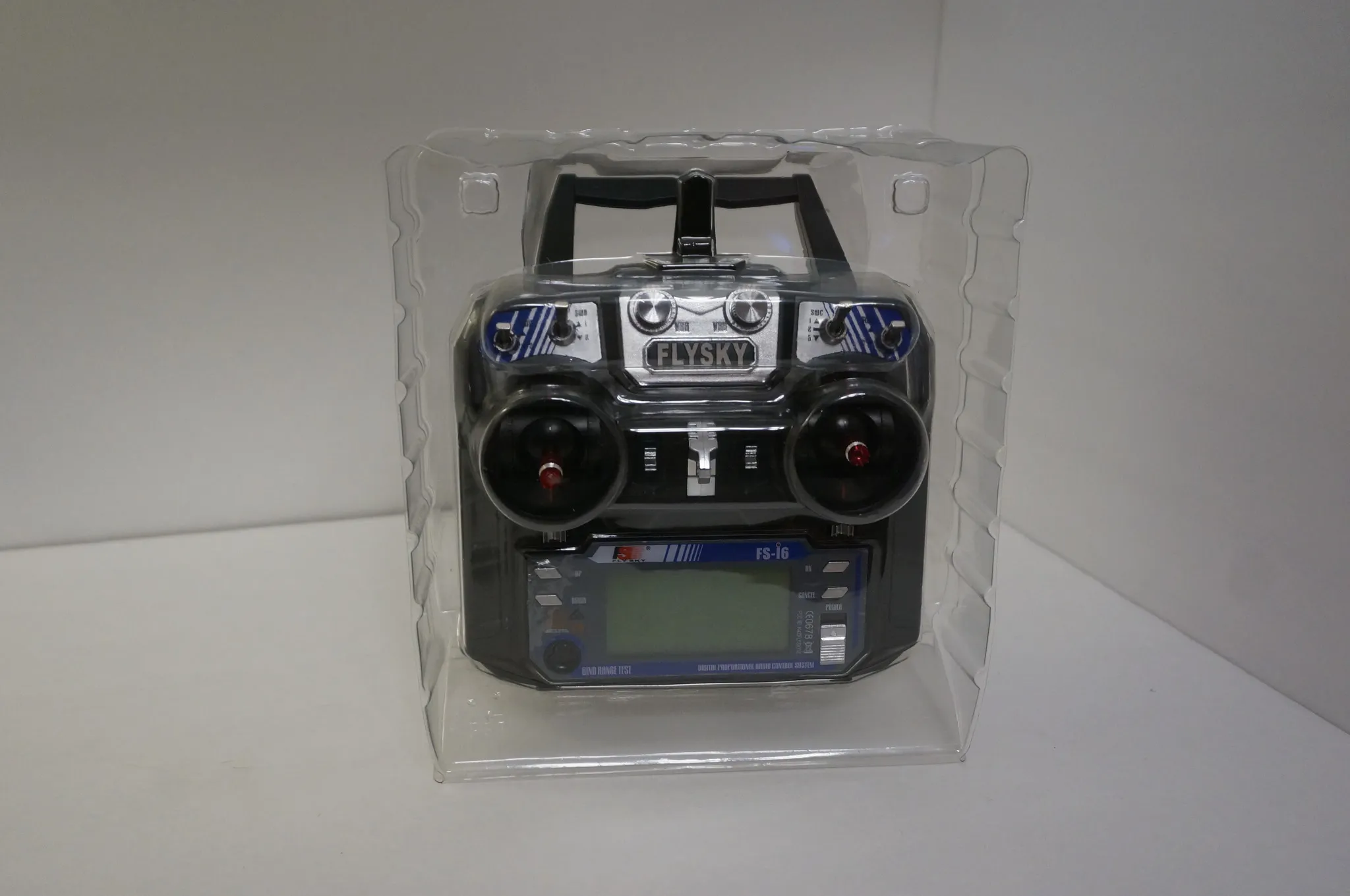
Here’s the box.

Inside is the cool protective plastic thing.
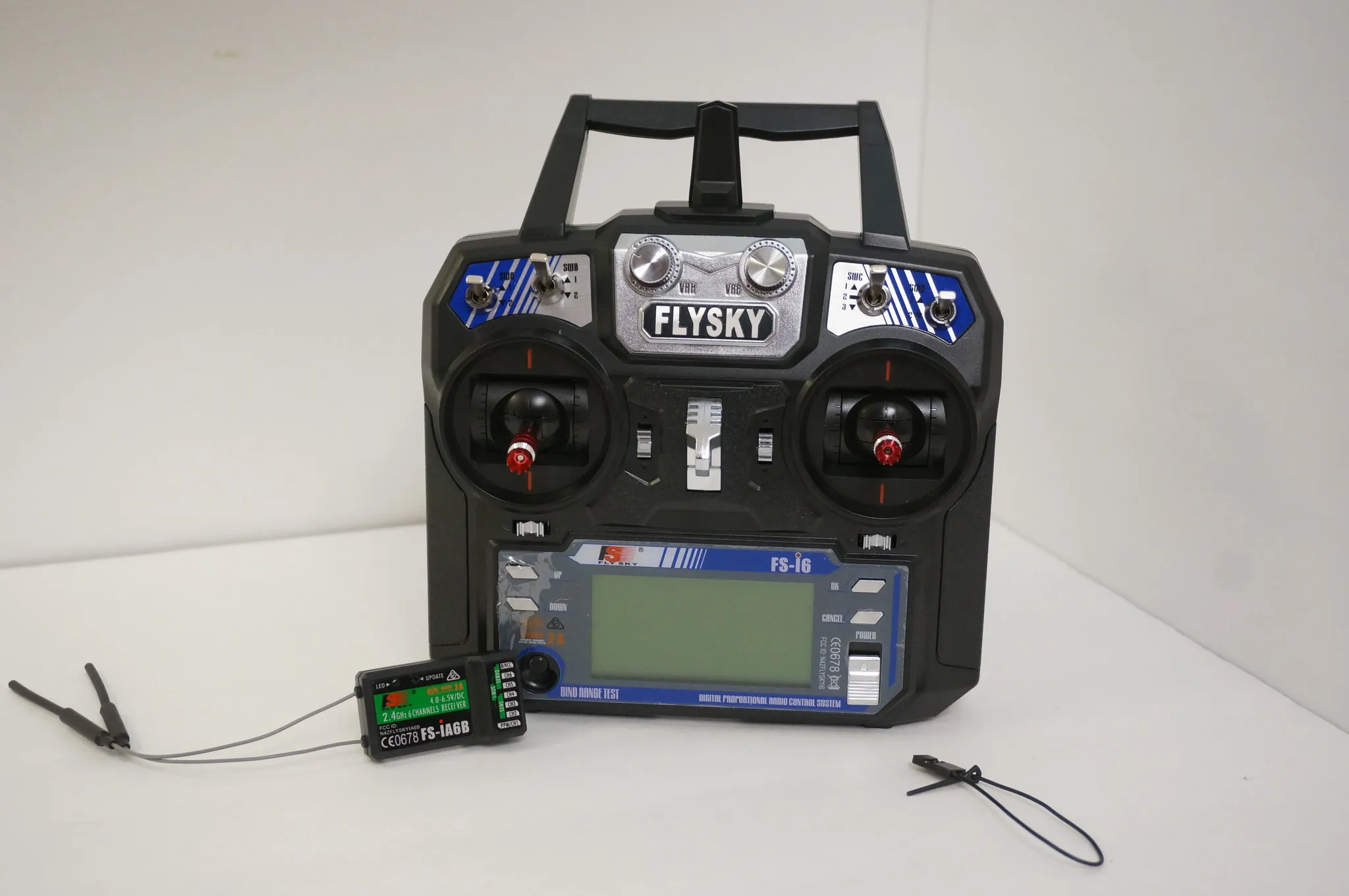
Get the version that comes with the iA6B receiver, which is PPM enabled.
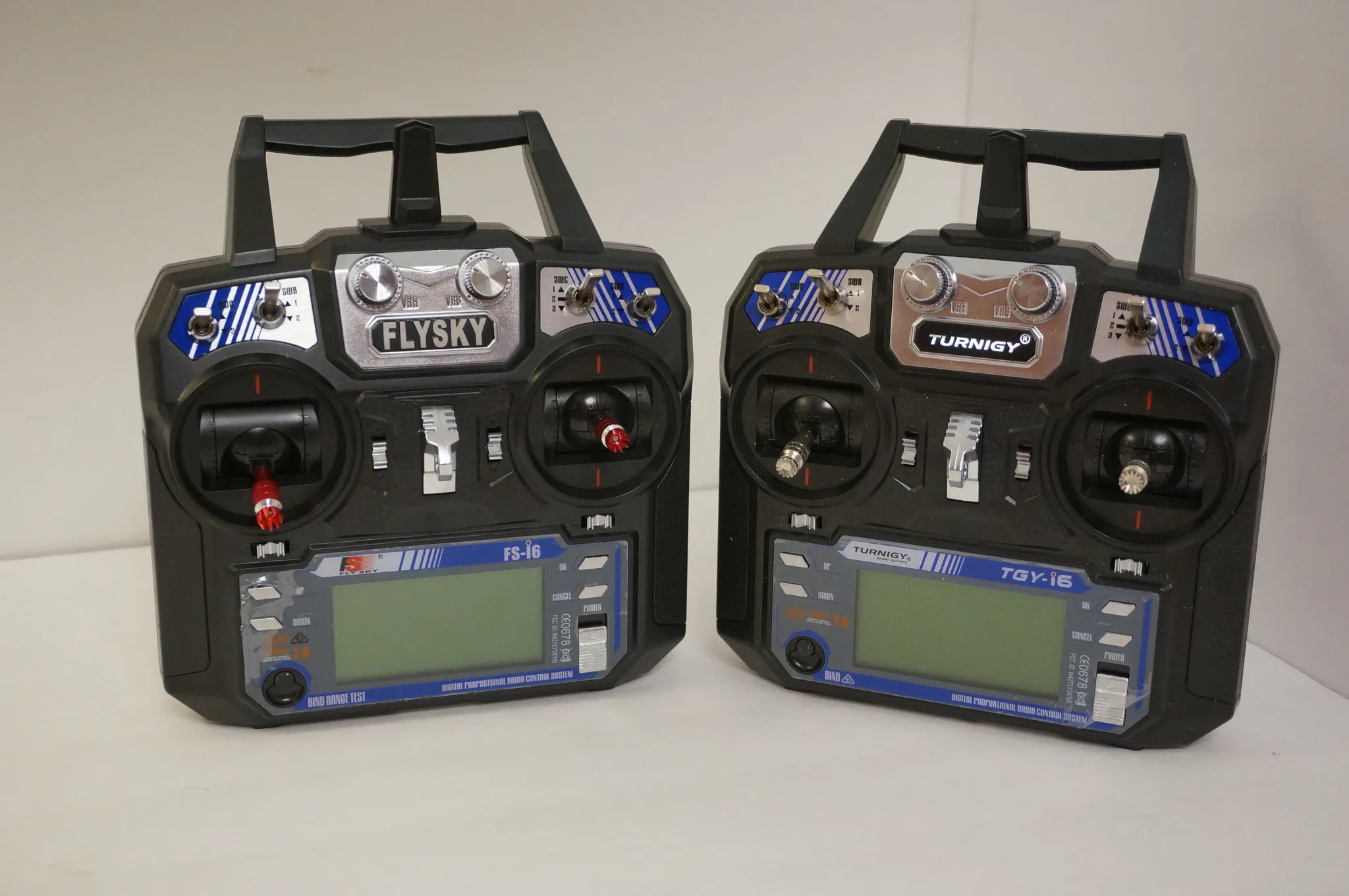
Side-by-side with the Turnigy i6
Review
The FlySky i6 is the ultimate beginner radio. We can make it even better by adding a DIY 4-in-1 module and re-painting it to look awesome.
Features
Switches and Knobs:
-
3x 2 position switch
-
1x 3 position switch
-
2x Knobs
Pros:
-
Diversity TX and RX
-
PPM or iBUS options
-
Nice Smooth Gimbals
Cons:
- No LIPO support without modification.
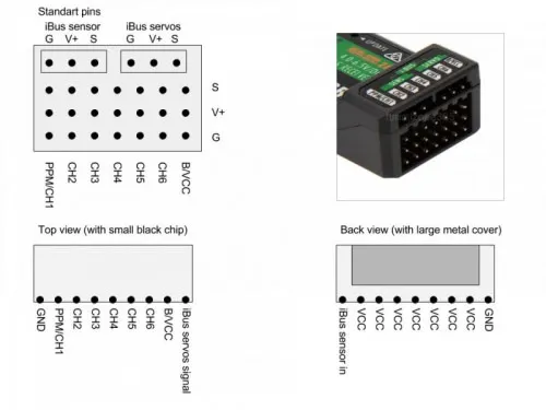
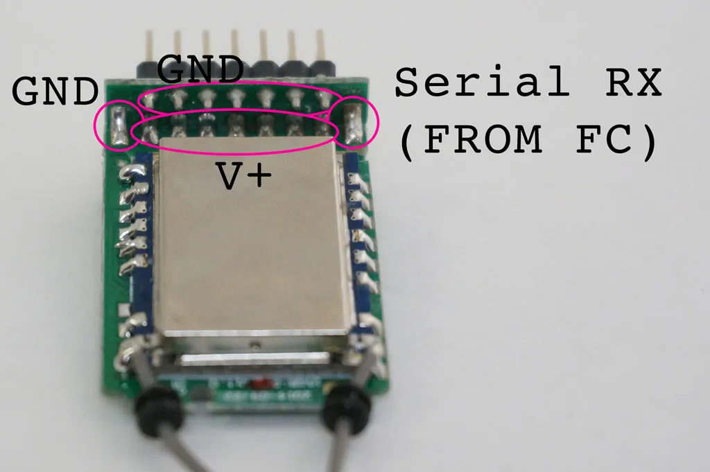
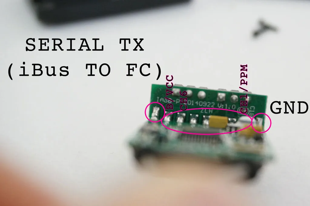
iA6B RX
Pinout:
Teardown
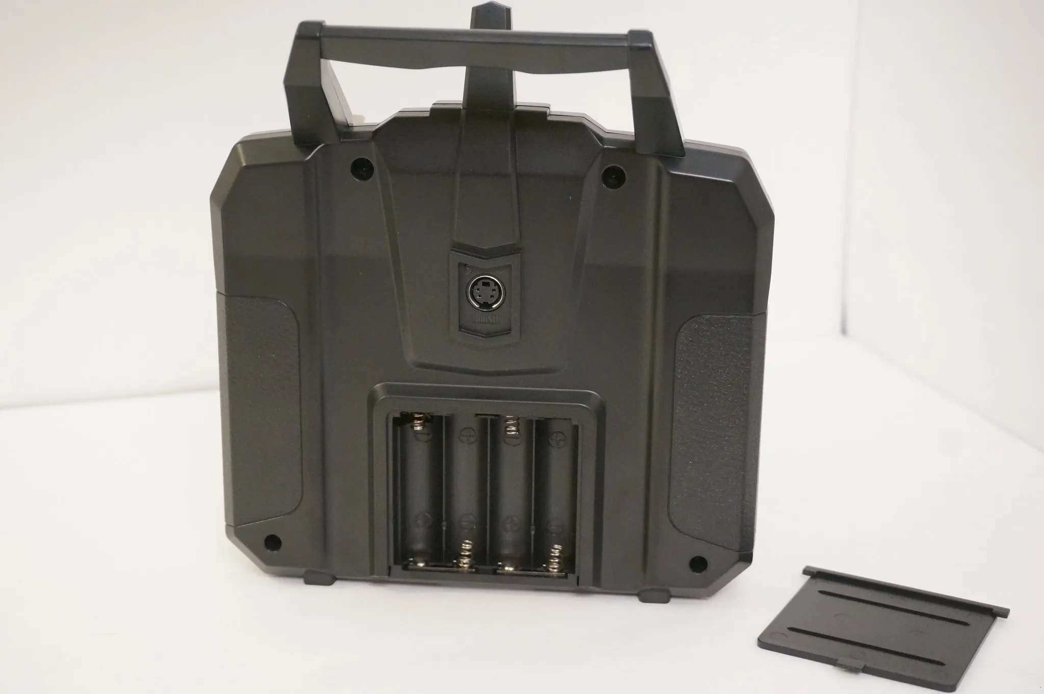
Remove the 4 screws on the back.
Crack it open. The antenna stub will probably fall out, no worries, just hold onto it.
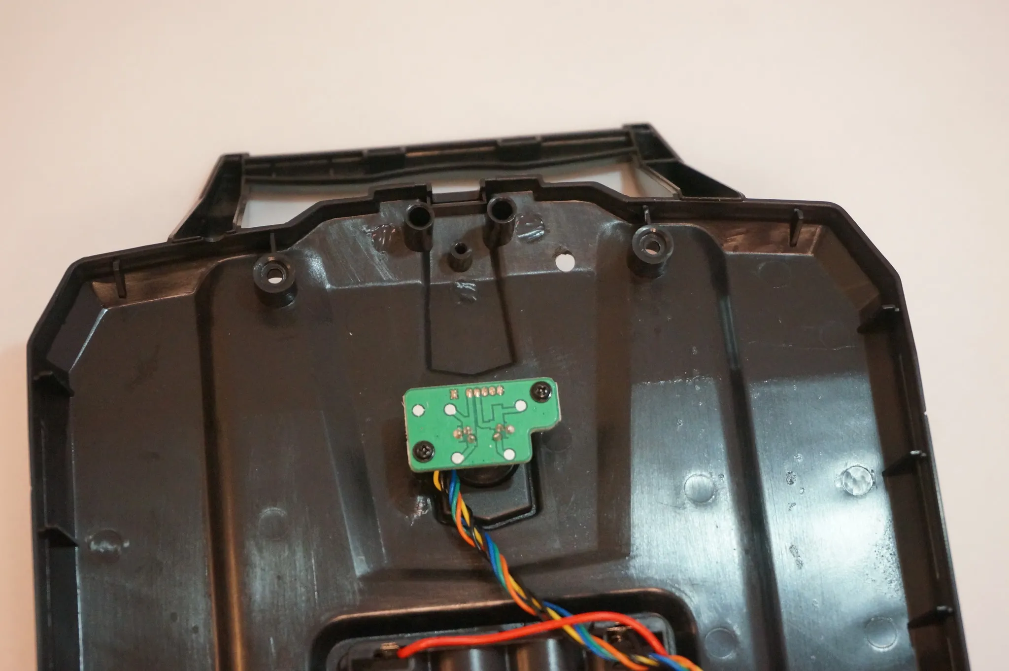
Disconnect the bottom two plugs from the mainboard and separate the front and back case.
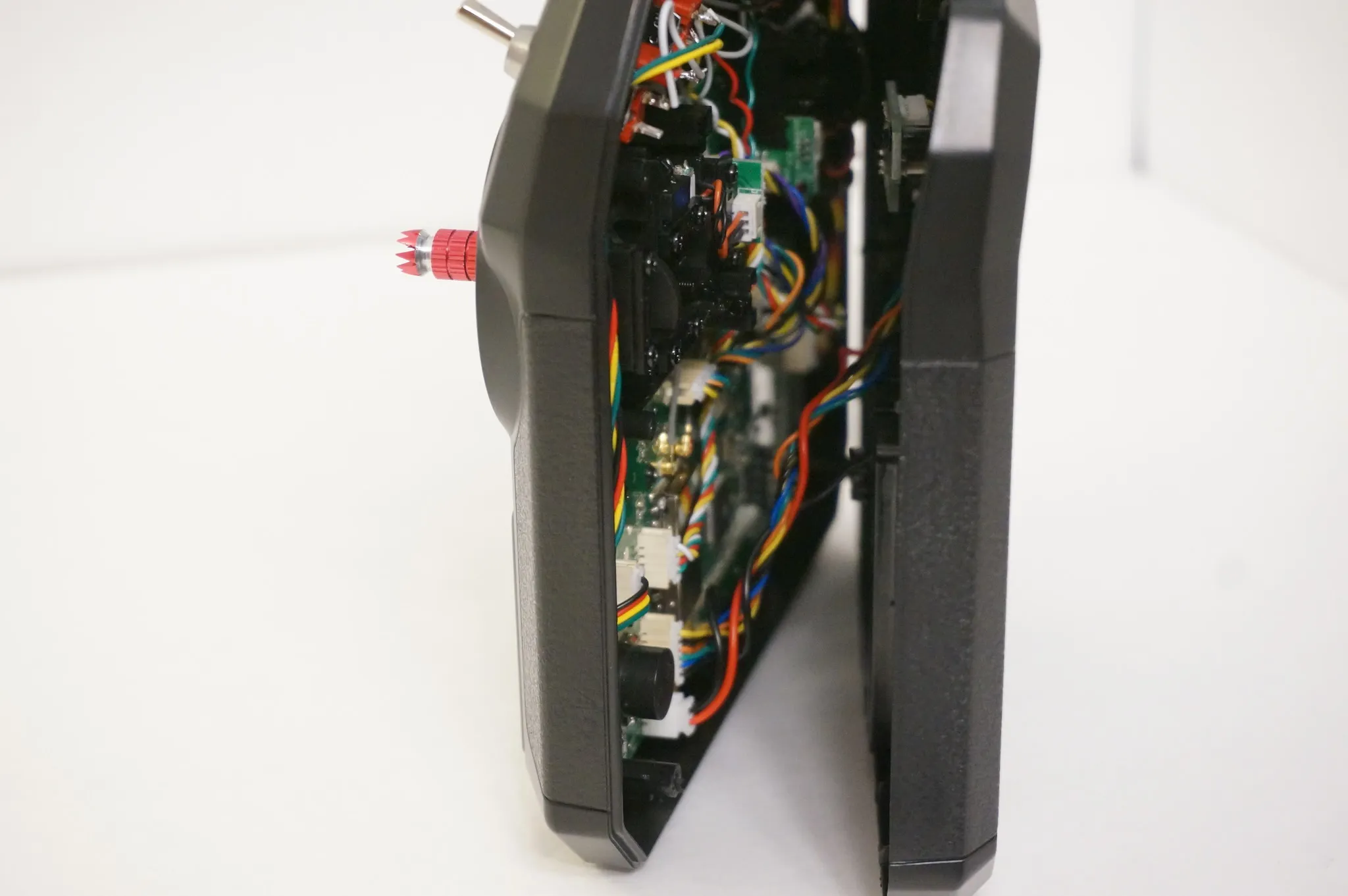
Separate the front and back.
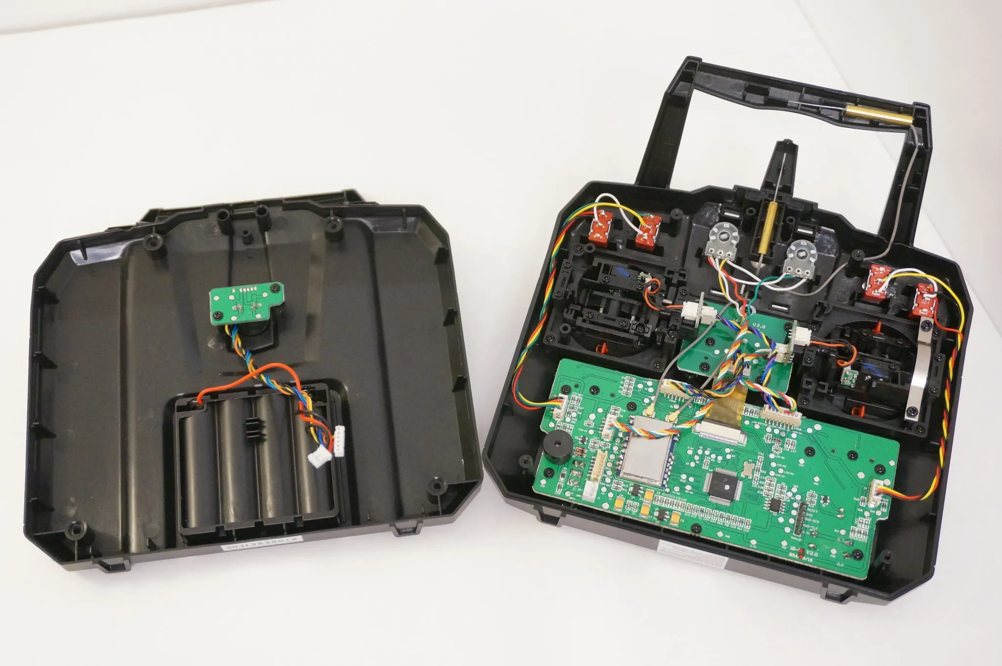
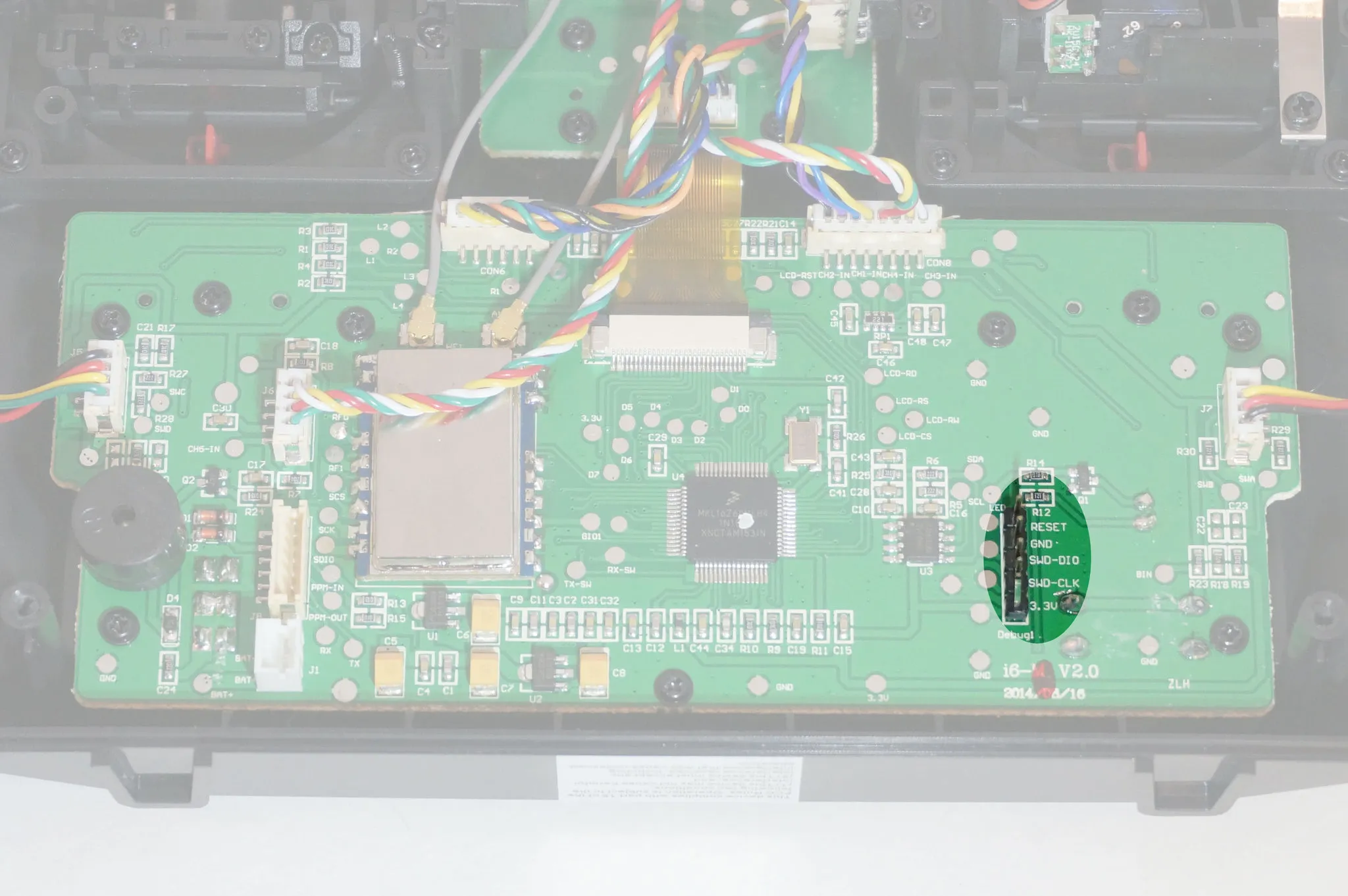
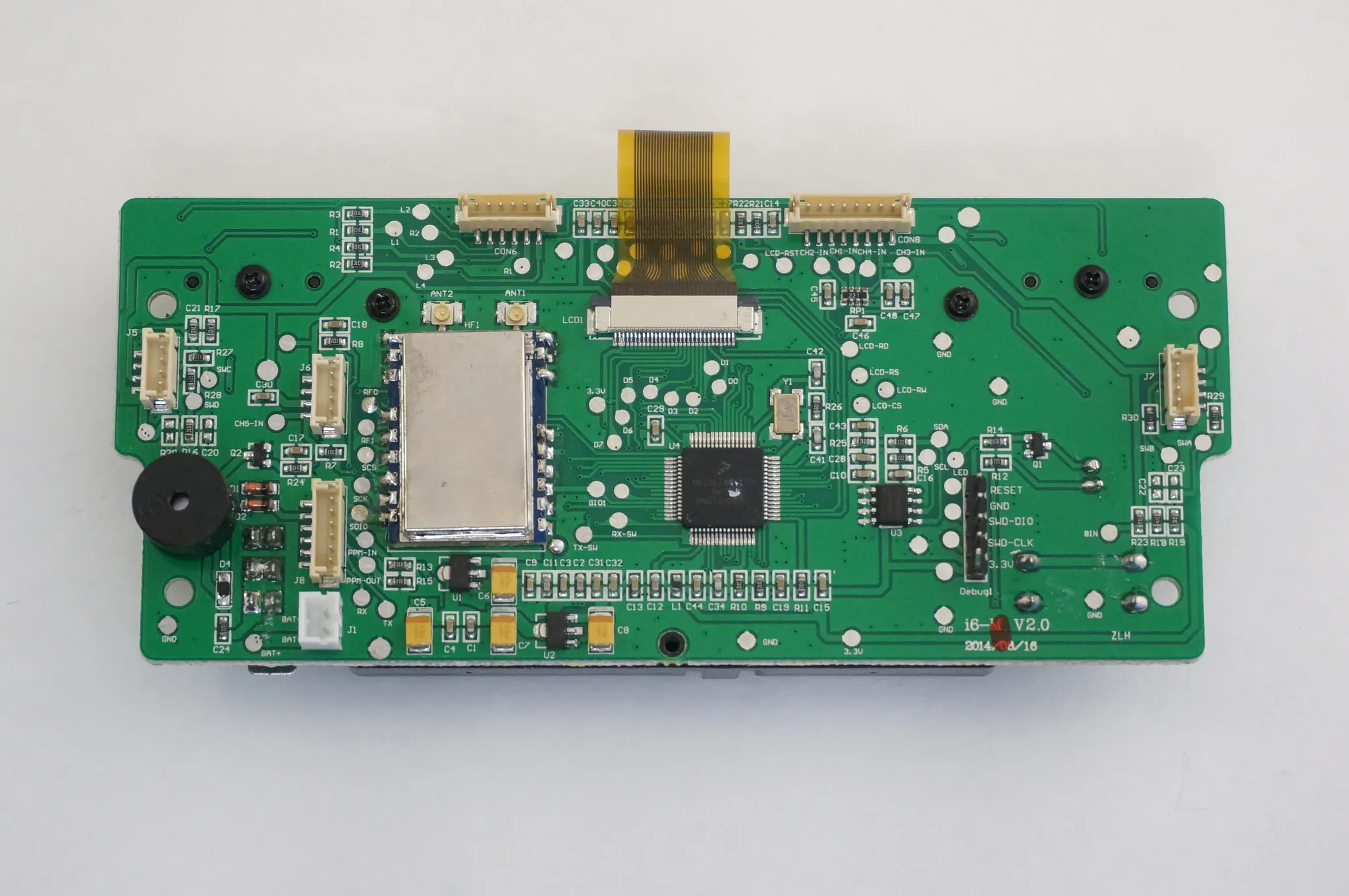
Note the two antennas for the diversity transmitter and MKL16Z64VLH4 Freescale Kinetis microcontroller Datasheet is here
There is a populated SWD port on the right for easy debugging.
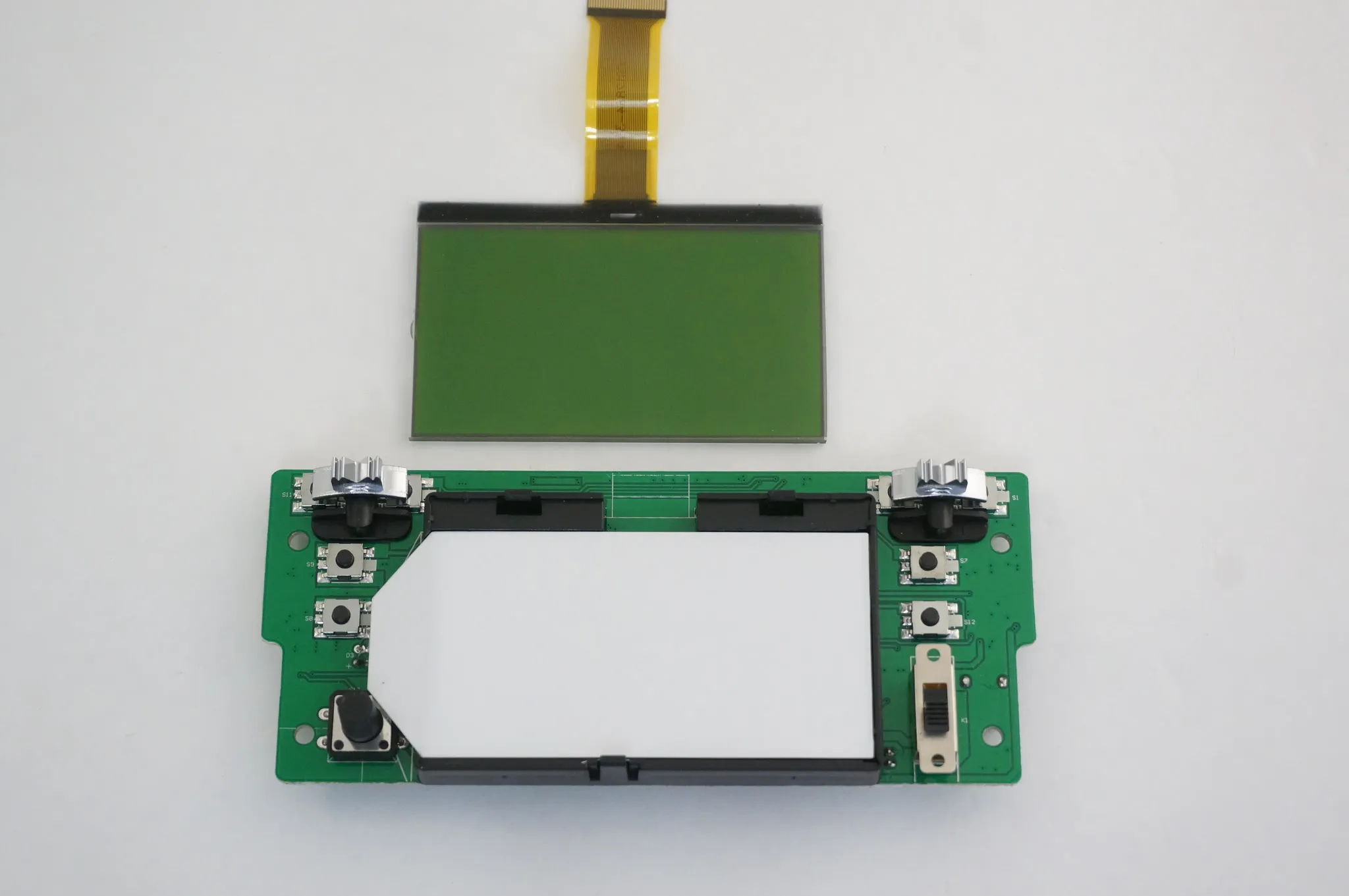
Removing the 4 outer screws on the display module we can pull the display up.
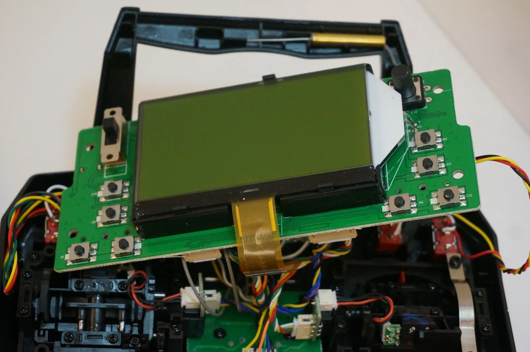
Disconnect all the plugs (antennas too, unlike the photo).
And the board can be removed.
The LCD can be removed by pulling the lower clip down slightly and lifting the LCD.
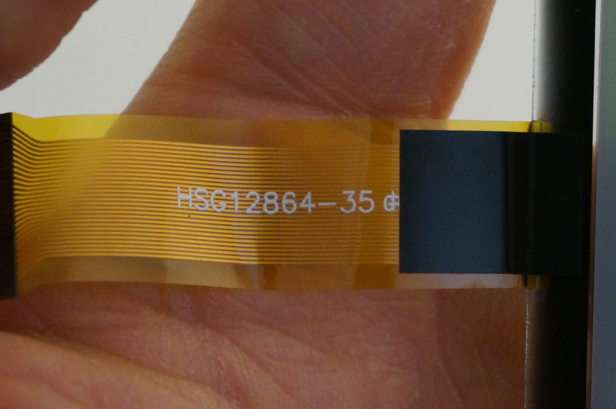
The display cable shows the only markings on the display HSG12864-35.
The backlight is soldered in place, but we can see the other side of the PCB by pulling it up gently.
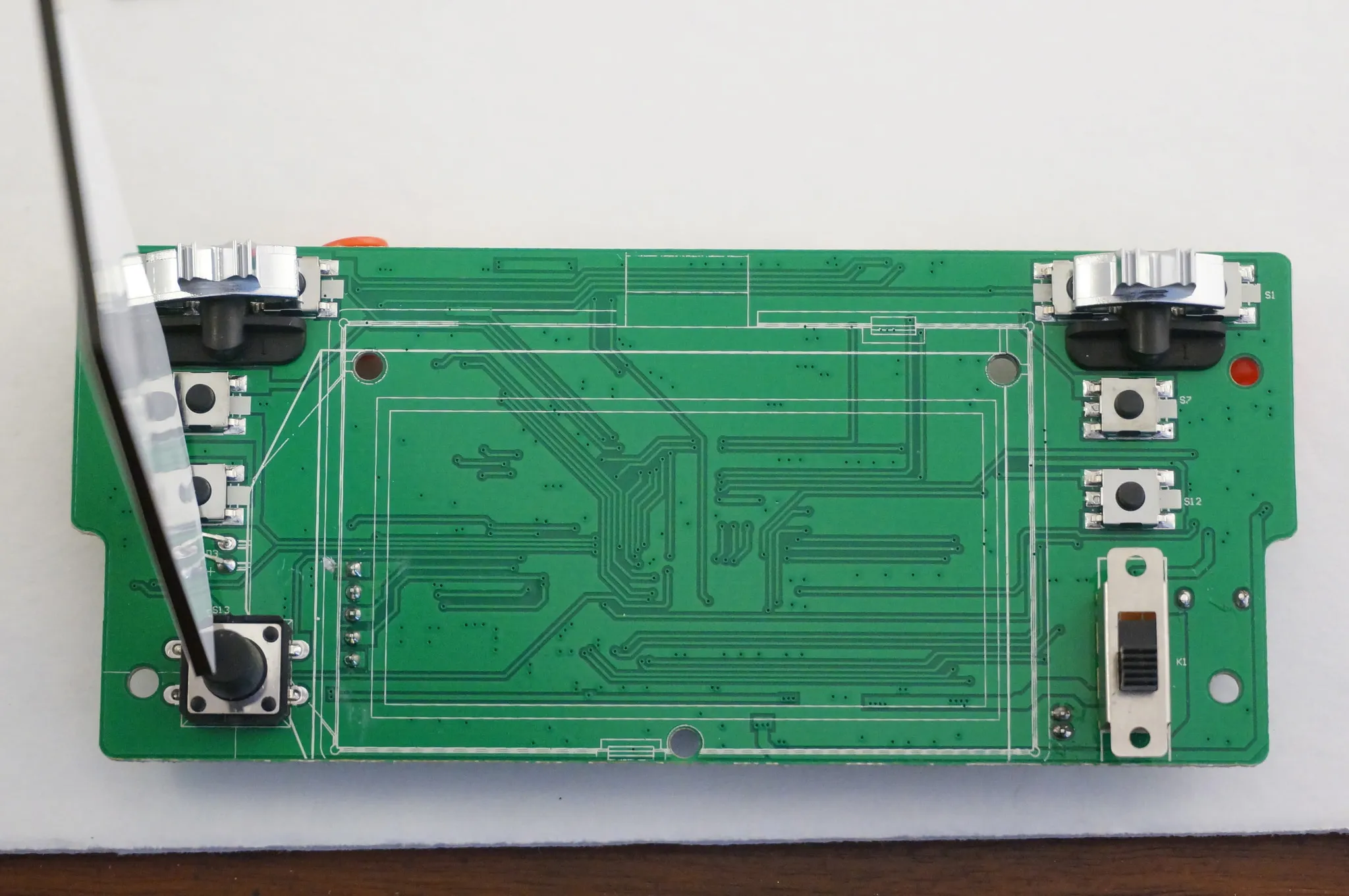
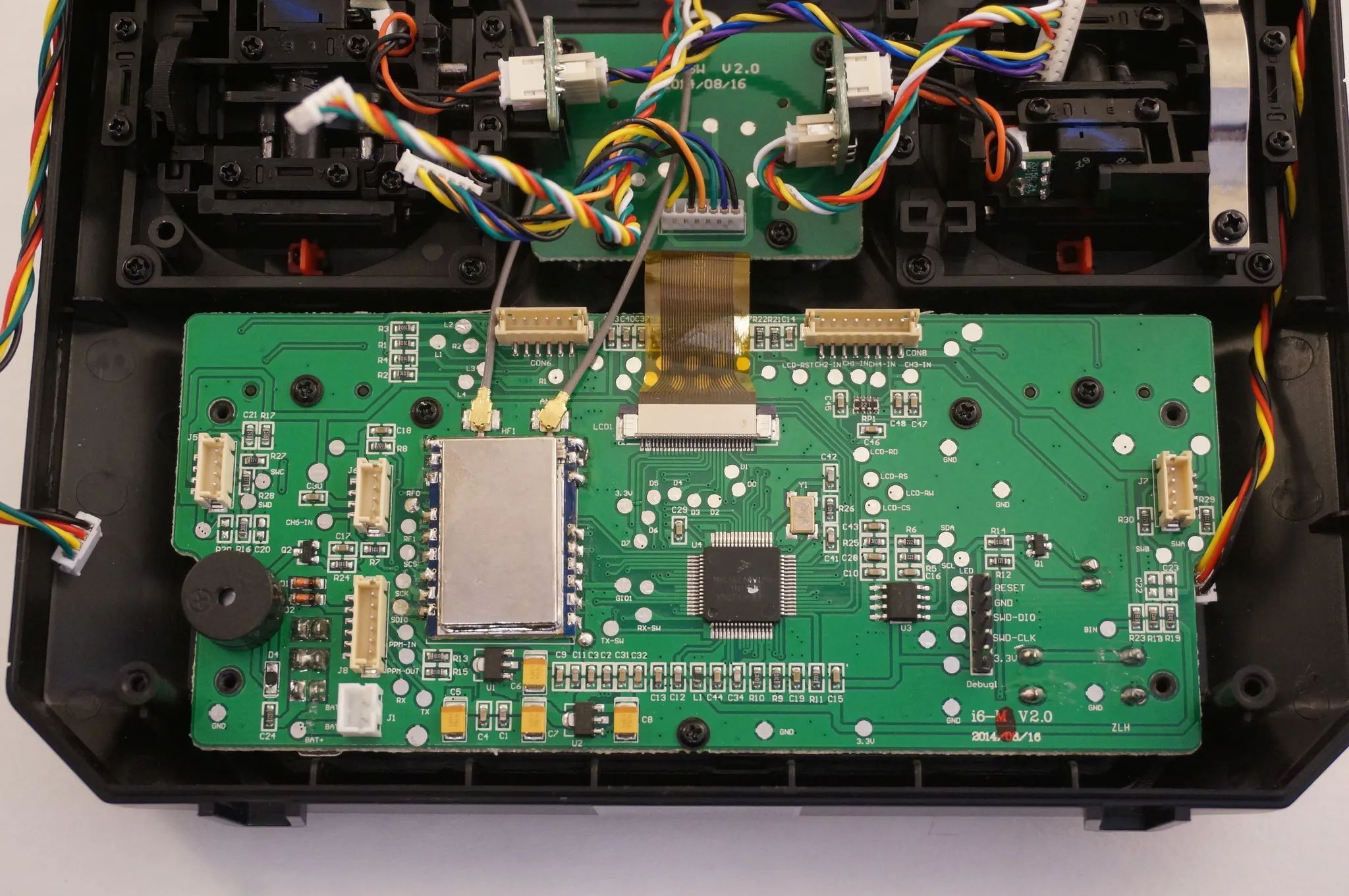
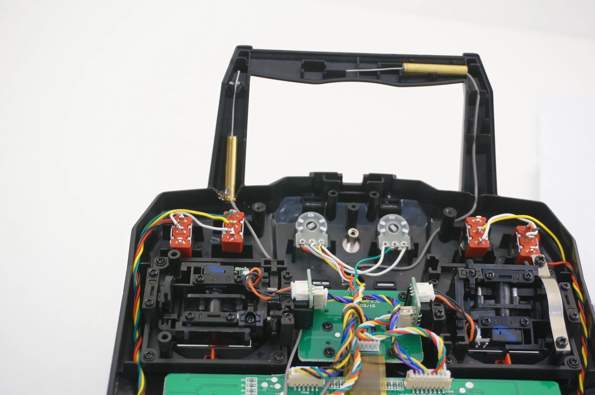
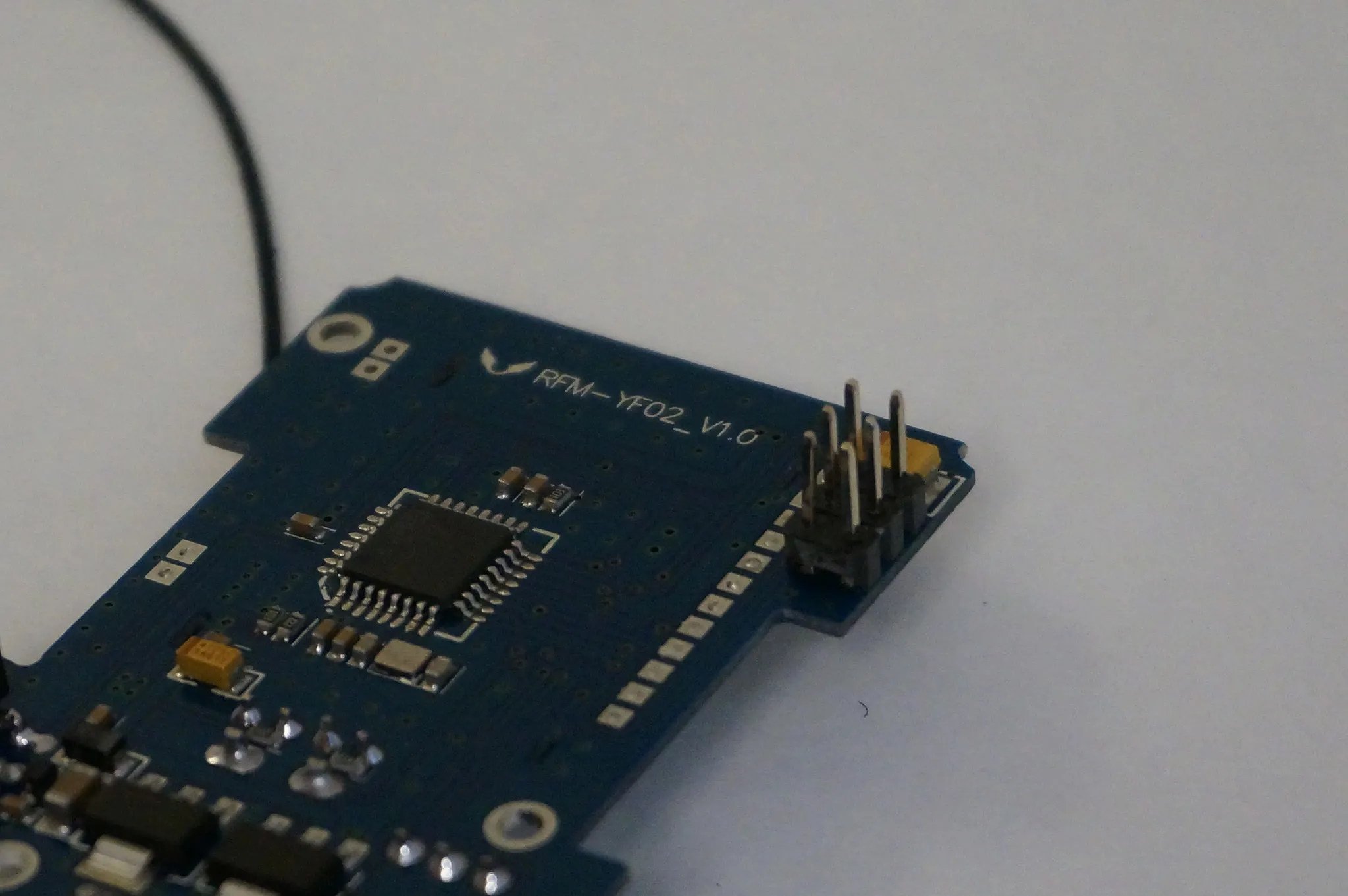
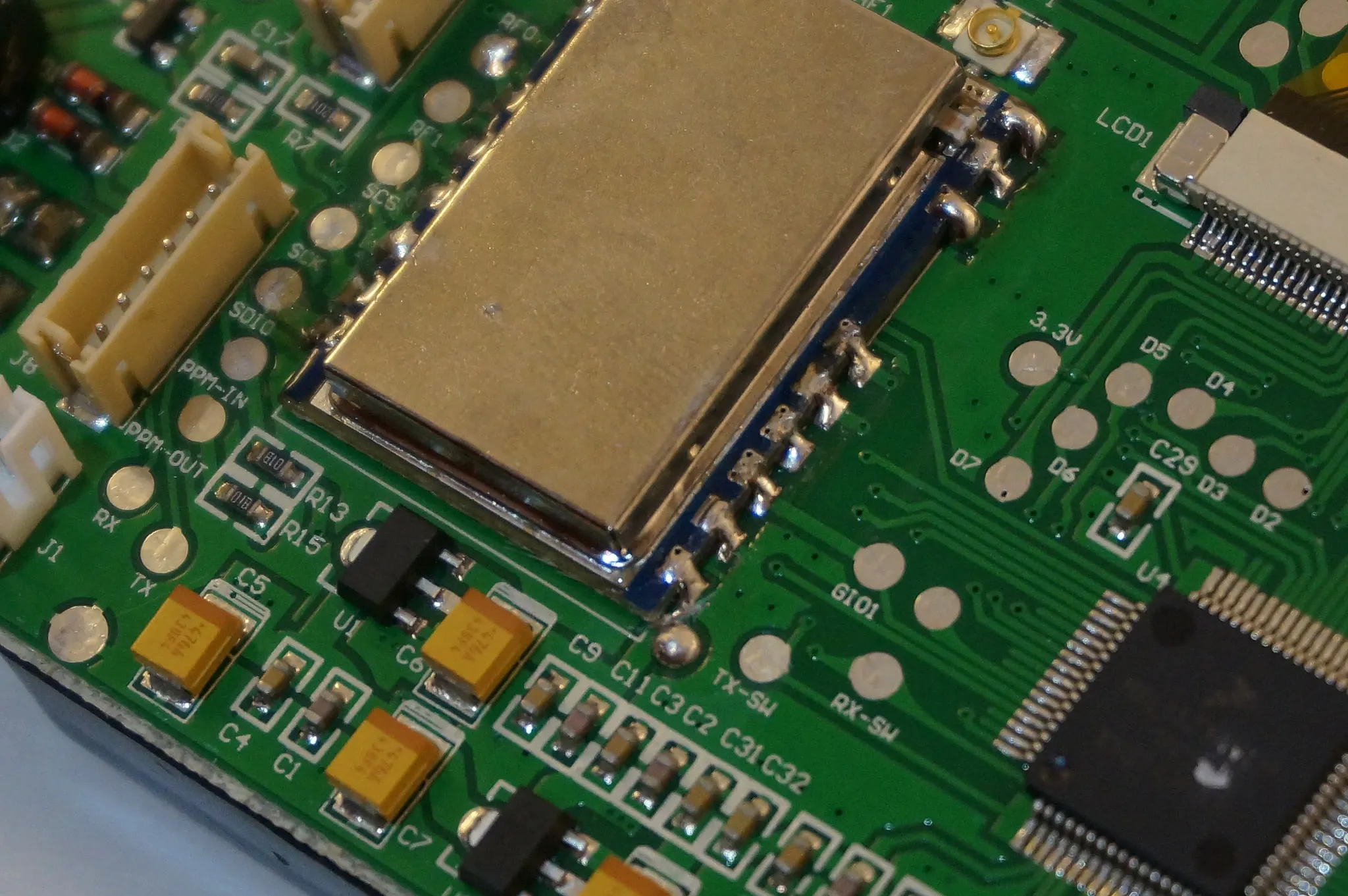
Removing the radio transmitter, we can see:
Firmware
I have dumped the version of the firmware shipped with my controller here. Use xxd -r [filename] to restore it to a flash-able bin:
/downloads/https-gist-github-com-nathants-1
Restore it as described here in my
DIY TX Module
WARNING! DRAGONS AHEAD READ THIS BEFORE PURCHASING OR INSTALLING THE DIY MODULE!
When I started this project, I hoped to install this DIY transmitter module which allows you to use the radio with basically any other protocol including FrSky and Spektrum. However, to do this I also wanted to disable the internal module, which turned out to be very difficult. Even after isolating the internal radio module from the power line, the module was still getting power from some other pins.
I then tried removing the build-in wireless module entirely, but that didn’t work either. Now that the module is out, my radio refuses to boot. So, this project is on hold while I write some custom firmware for the radio.
Consider the following a guide on how NOT to install the DIY module. While you may be able to get it to work, the range could be greatly reduced because of interference from the internal module. Therefore I suggest you buy a FlySky 9x instead, if you want to use the DIY TX module.
WARNING! Please read the above note, if you did not already.
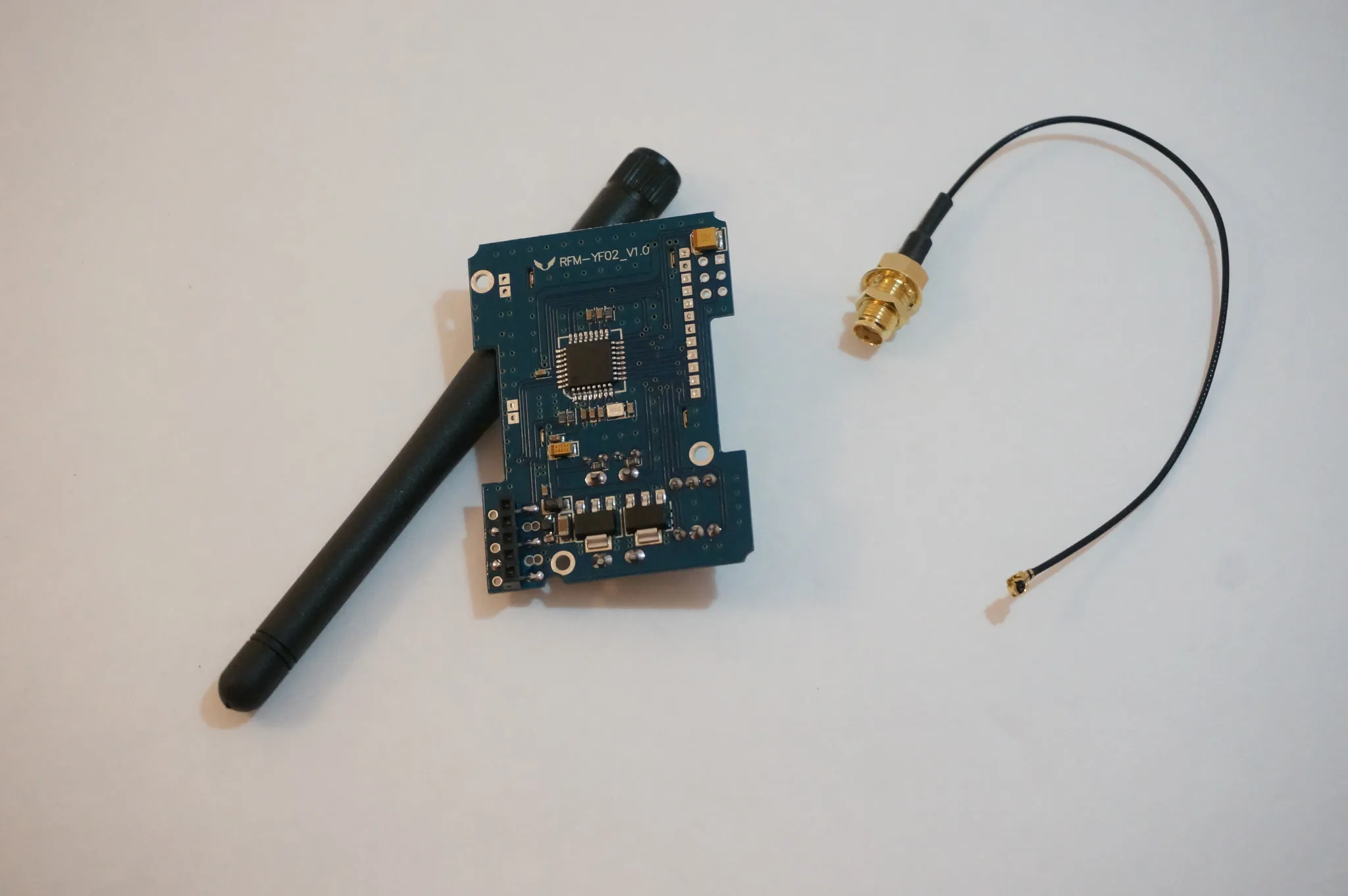
I’ll be using this DIY transmitter module which allows you to use the radio with basically any other protocol including FrSky and Spektrum.
I’ll install the module here.
Start by drilling a small hole for the knob. I held the module in place and used a sharp screwdriver to mark the case with a scratch.
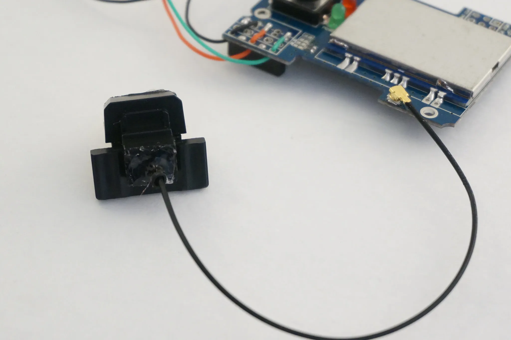
I then did the same thing on the second hole then test fit the module. I removed the antenna holder temporarily.
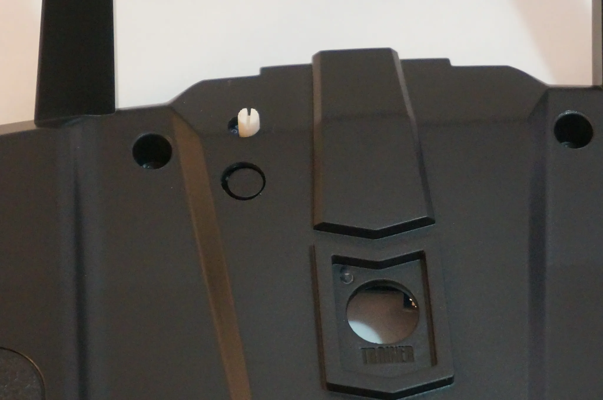
Re-routed the antenna into the handle by cutting a v shape in the little tabs. I used wire clippers for this.
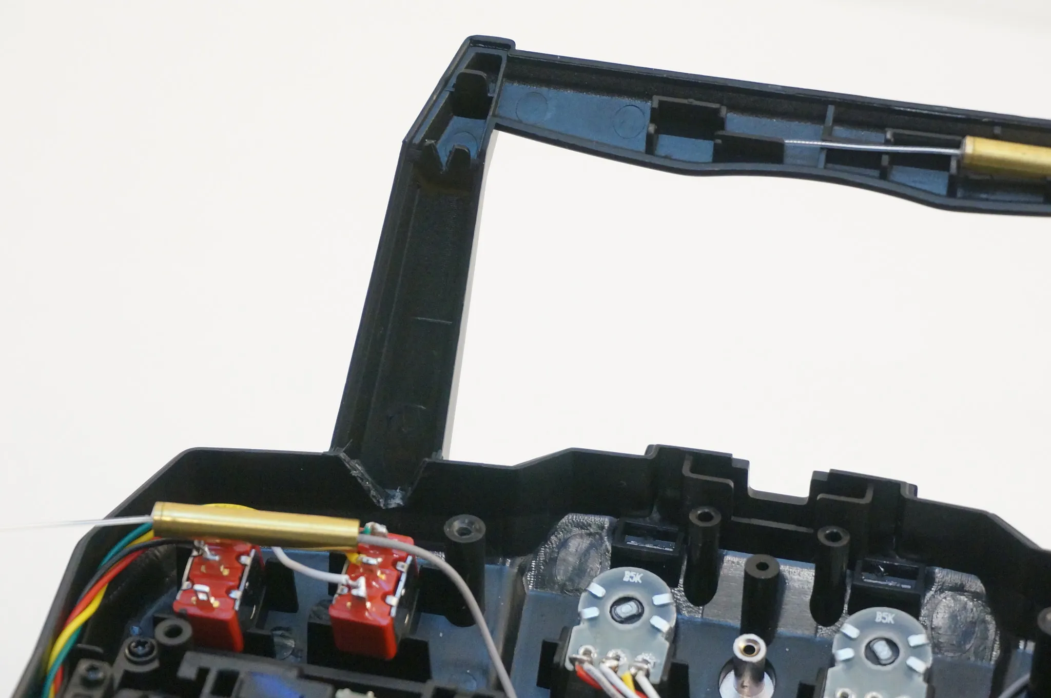
Then I secured the antenna with a small dab of hot glue.
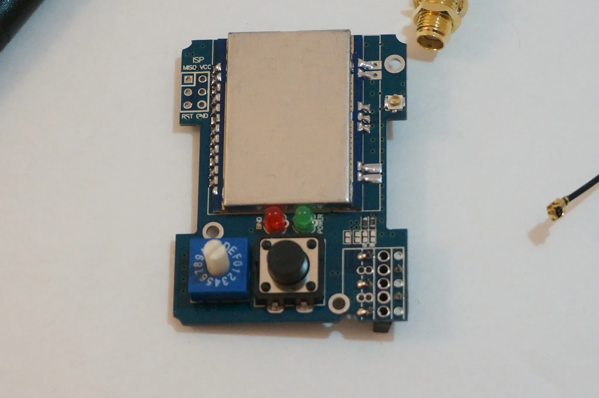
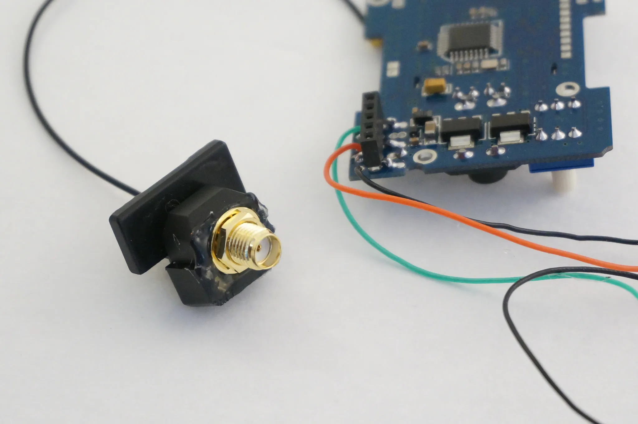
Solder some leads onto the module.
Green: PPM
Black: GROUND
Red: V+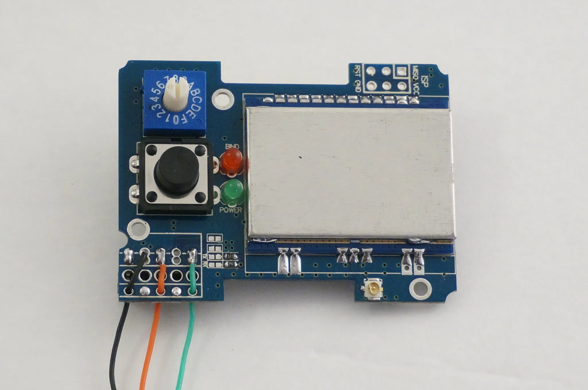
And solder on the ISP header so you can re-program the module later without removing it. I soldered it on the back side, so be aware that the pins will be flipped from the normal ISP header. I give the pinouts below in the 4-in-1 DIY TX Module Programming section.
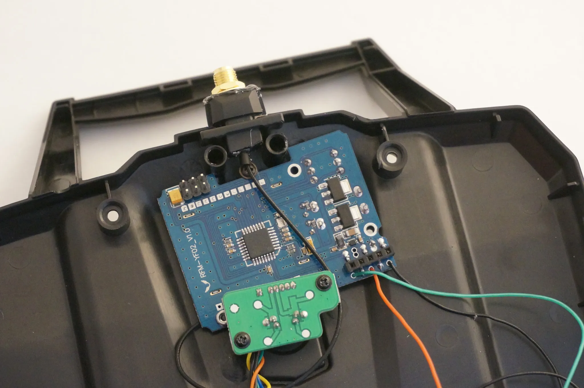
To install the new antenna’s SMA adapter, I cut the old antenna holder on both sides then used a reamer to open up the hole a bit.
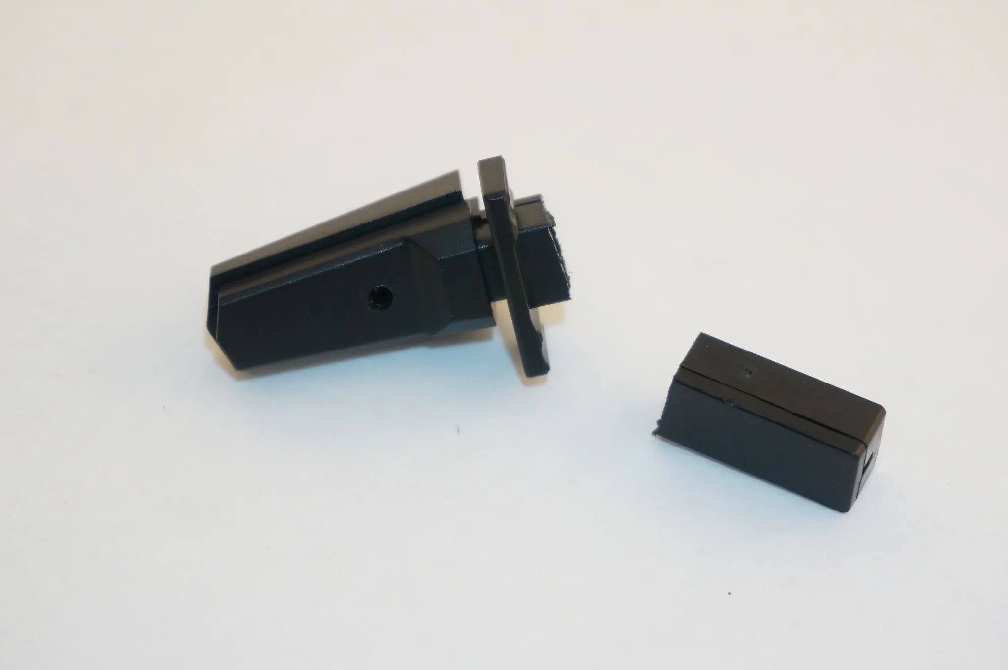
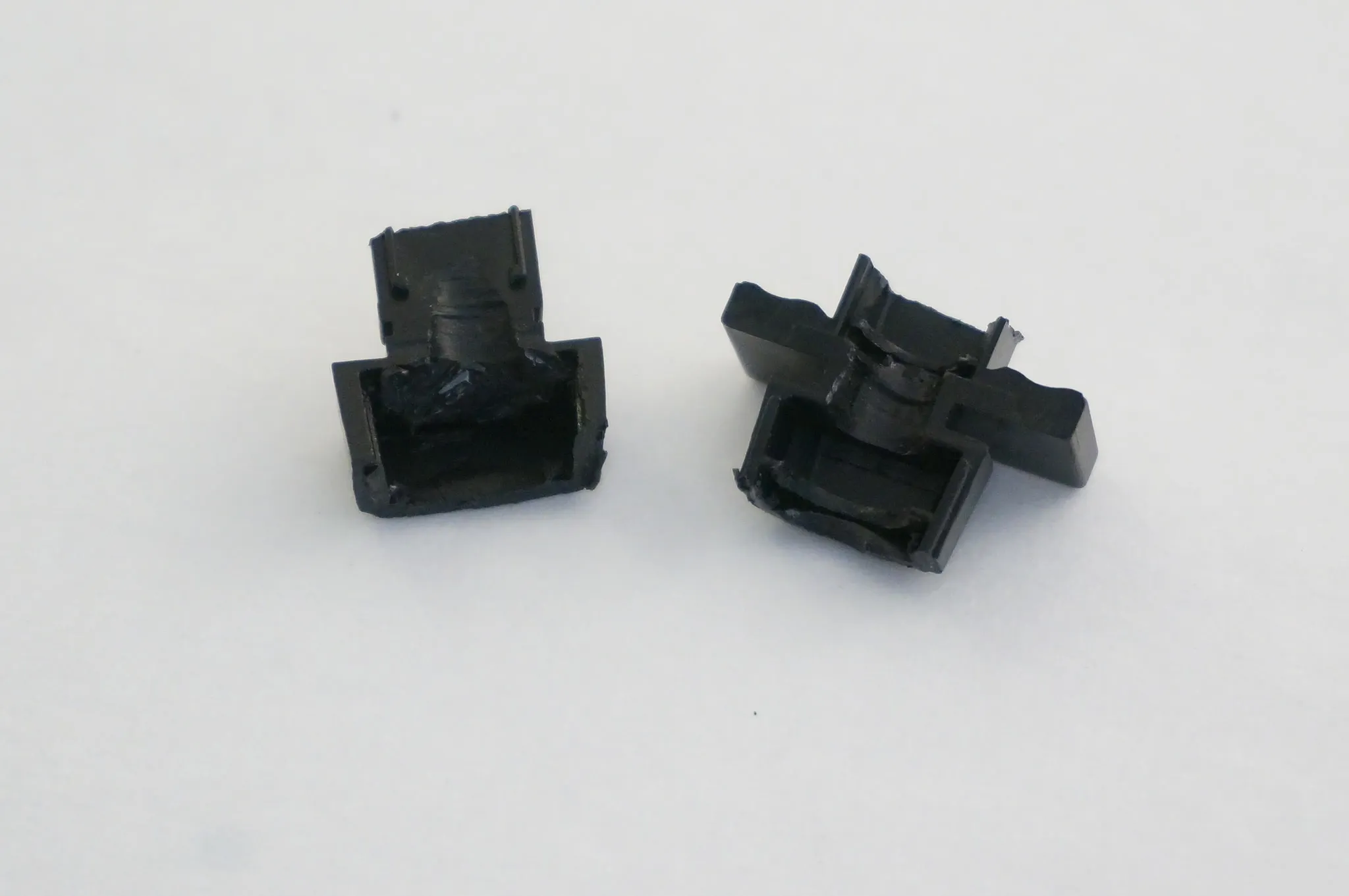
Once you’ve got that opened enough, the SMA adapter should fit nicely and can be secured with some hot glue.
I installed the lock washer and nut. They don’t do anything except make it look a little nicer.
Then I installed the module like so, using an extra screw in the existing post to hold it in place.
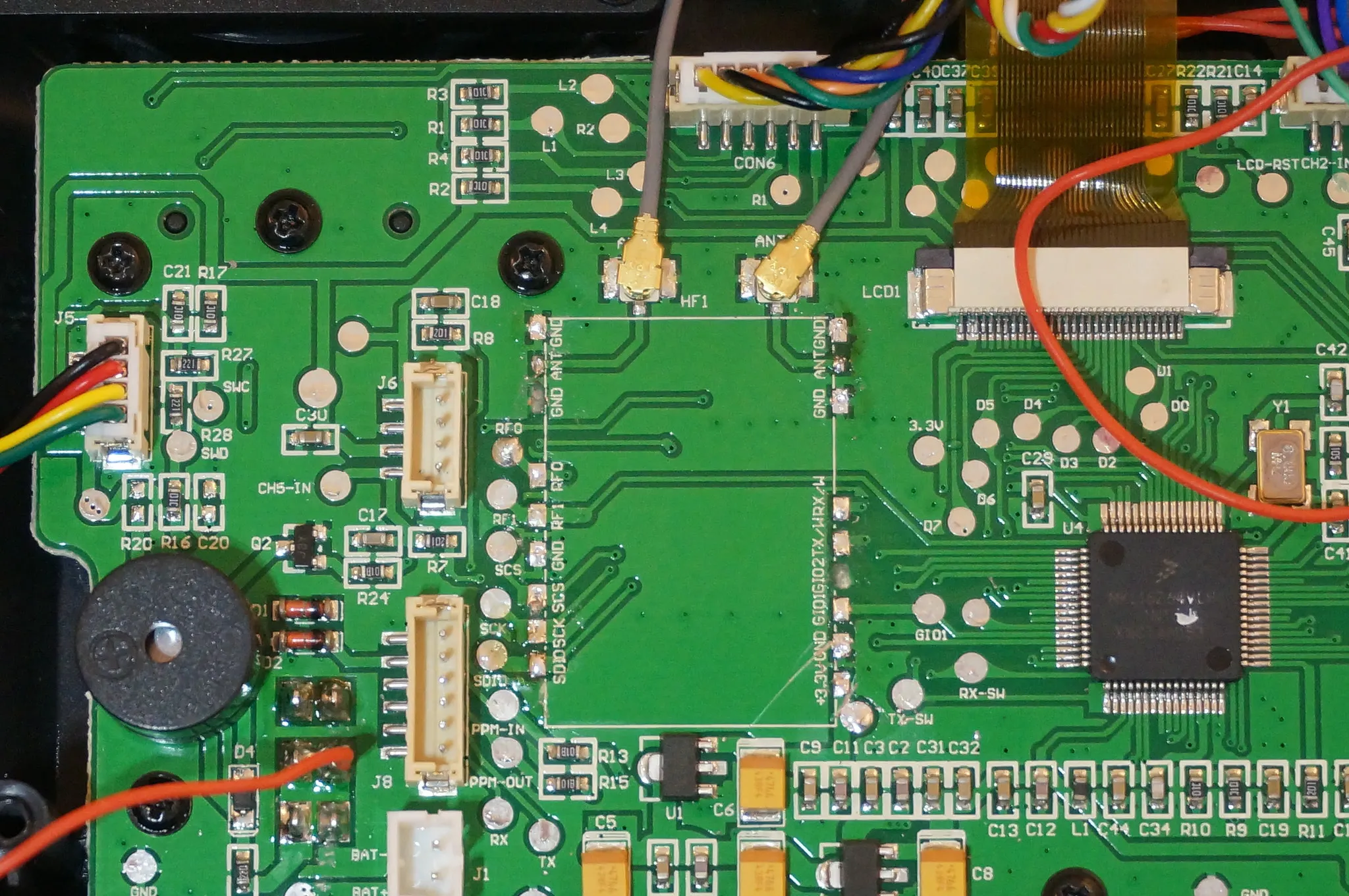
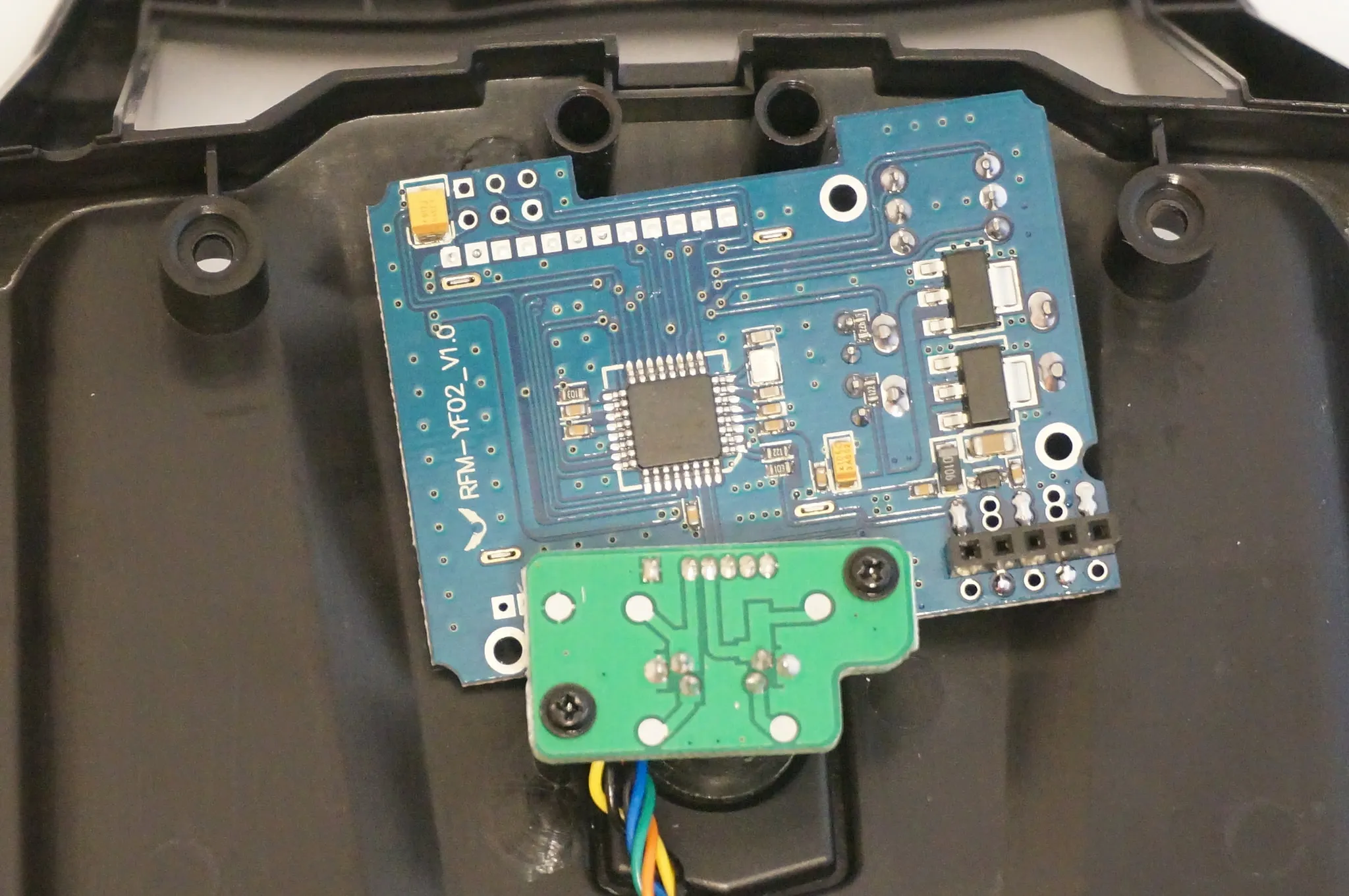
Now, here’s the plan. Normally, when you power on the transmitter, the radio module (silver thing in the photo below) receives power as well. This is normally fine, however with our new module, we’ll want to disable the internal radio while the DIY module is turned on.
For this, I’m going to use a switch. You could just cut the trace as described below, to disable the internal module entirely, which would be fine, but the internal module should be a few MS faster than the DIY module, since the internal module is directly connected to the main MCU and does not need PPM conversion like the module. Therefore, it is slightly better to use the internal module for FlySky receivers, even though the DIY module does support FlySky RX.
I’ve installed mine in the front, but my switch was small and this was rather hard to do. I suggest you get a larger switch and install it in the back.
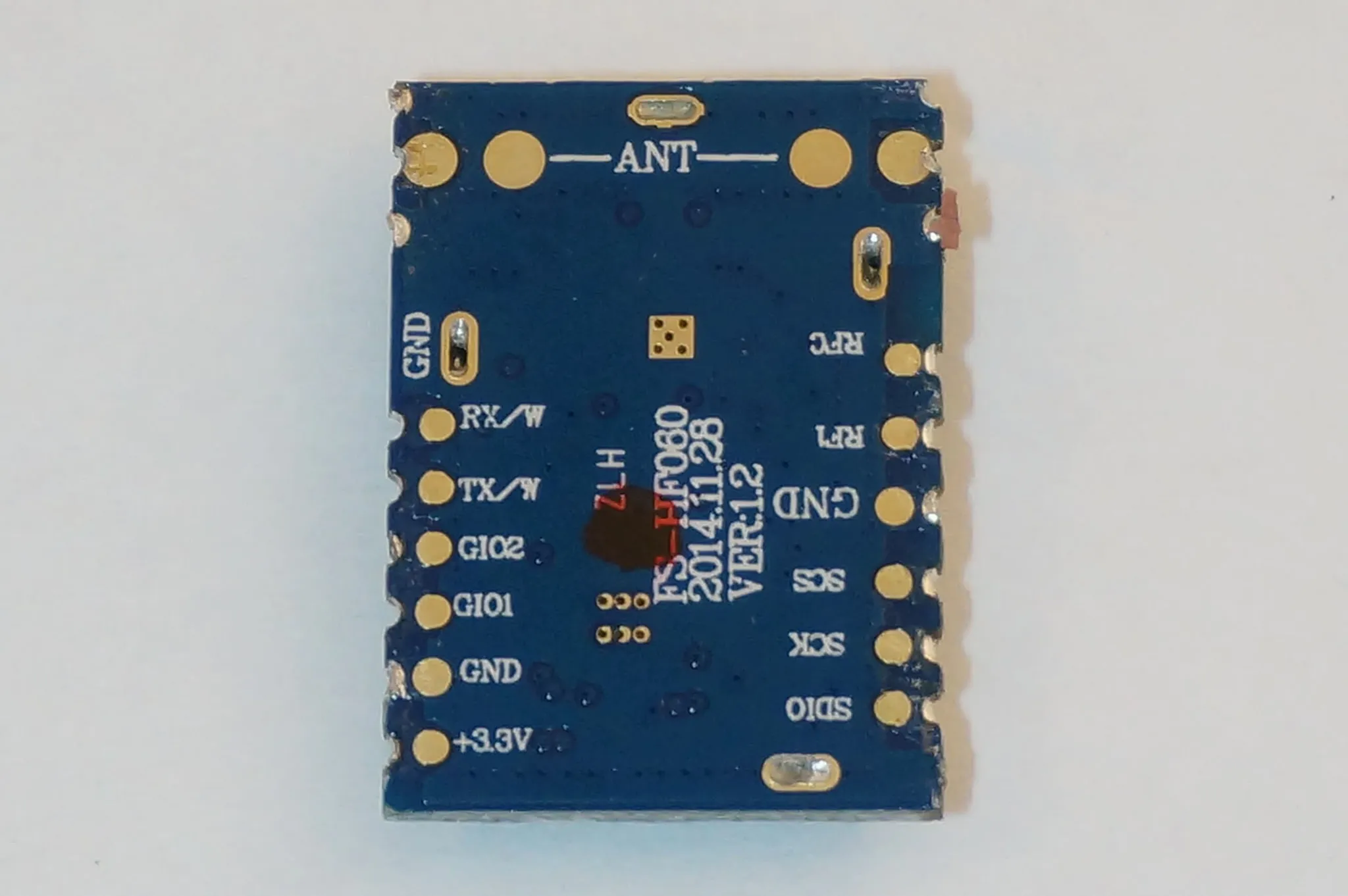
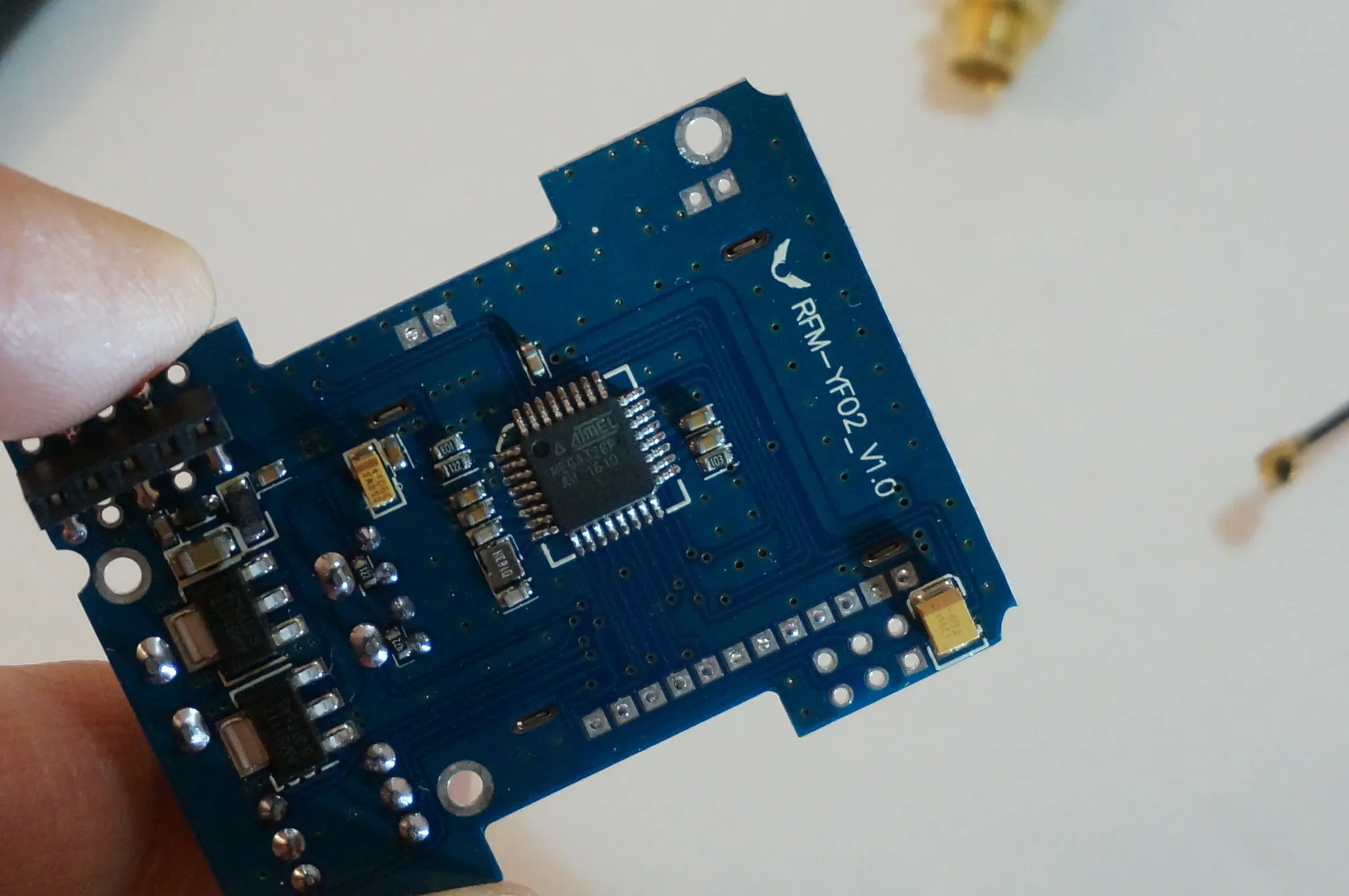
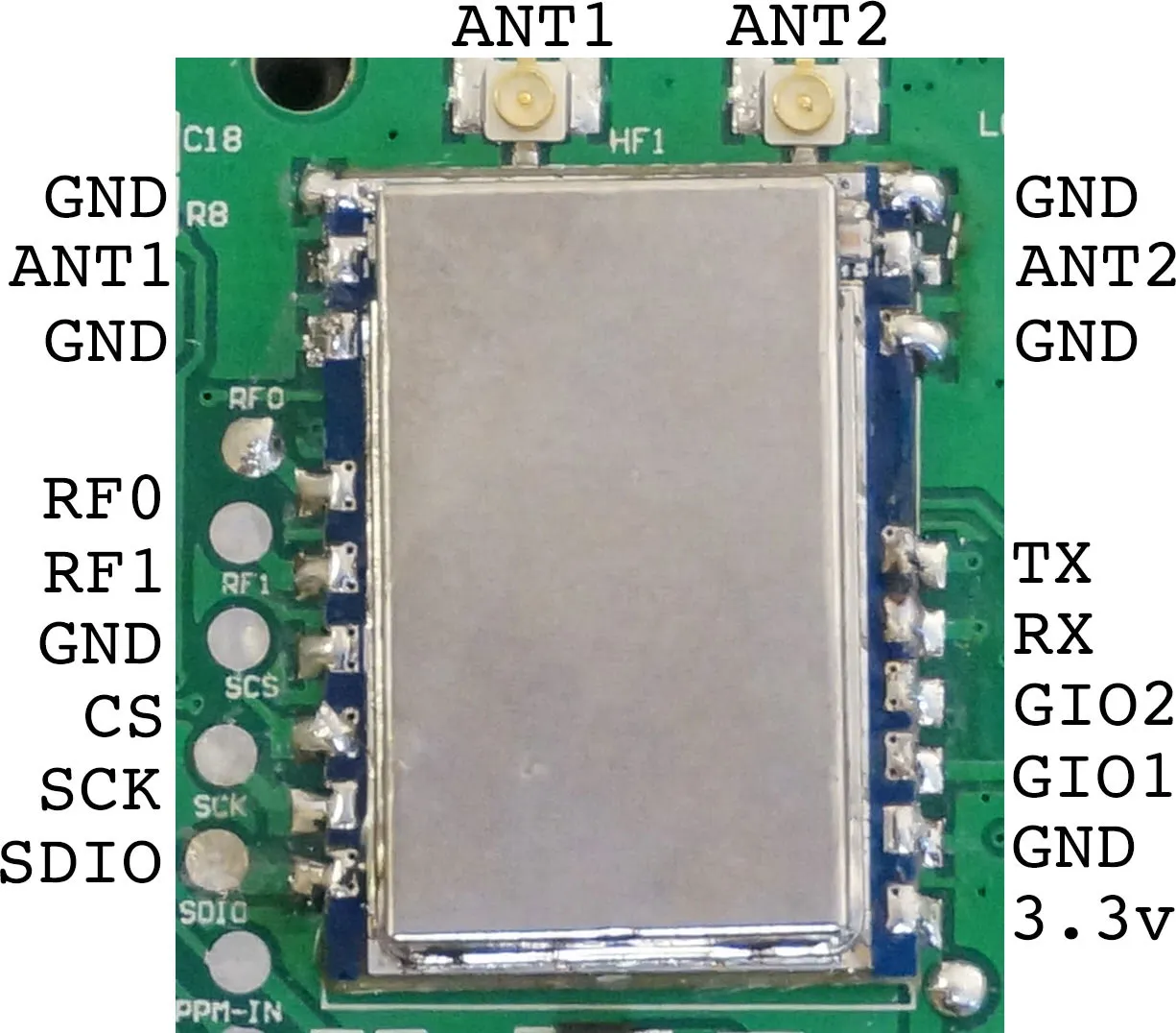
To use the switch, we’ll need to cut a trace on the PCB. To figure out which one, checkout this pinout for the radio module. As this module does not have the standard A7105 module, I reverse engineered the one on the board.
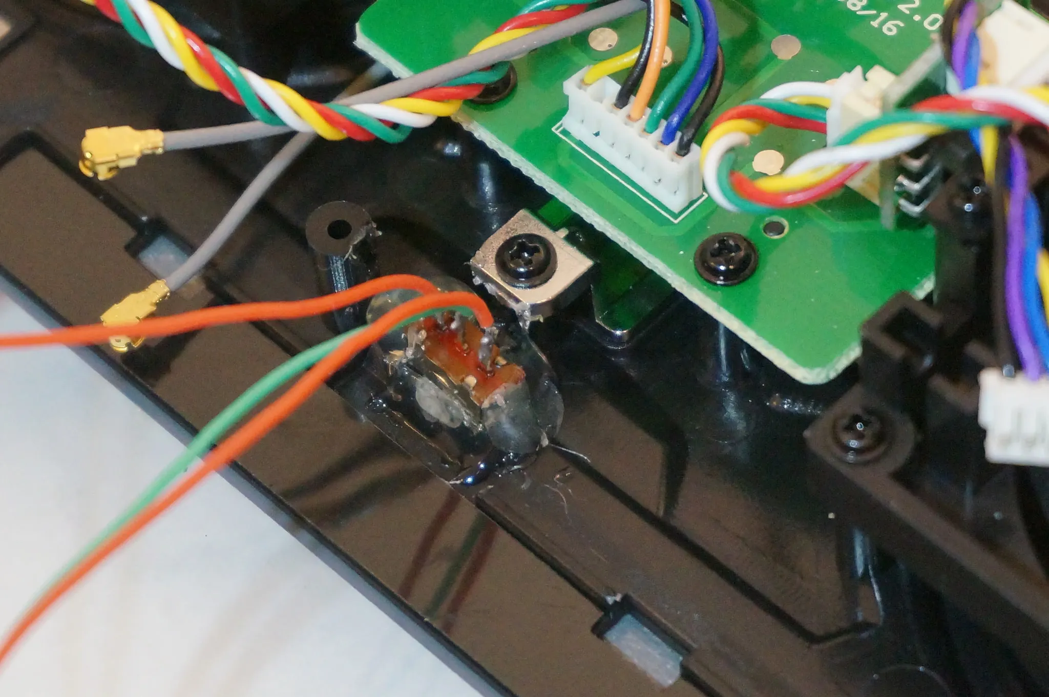
We need to cut the power line between the PCB and the radio module. Right here.
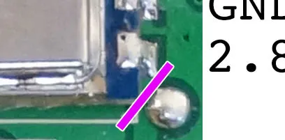
Take a new razor blade and make a cut as shown above. Once you’ve made the cut, check the continuity between the solder points on each side. Here’s what it looks like when we’re done.
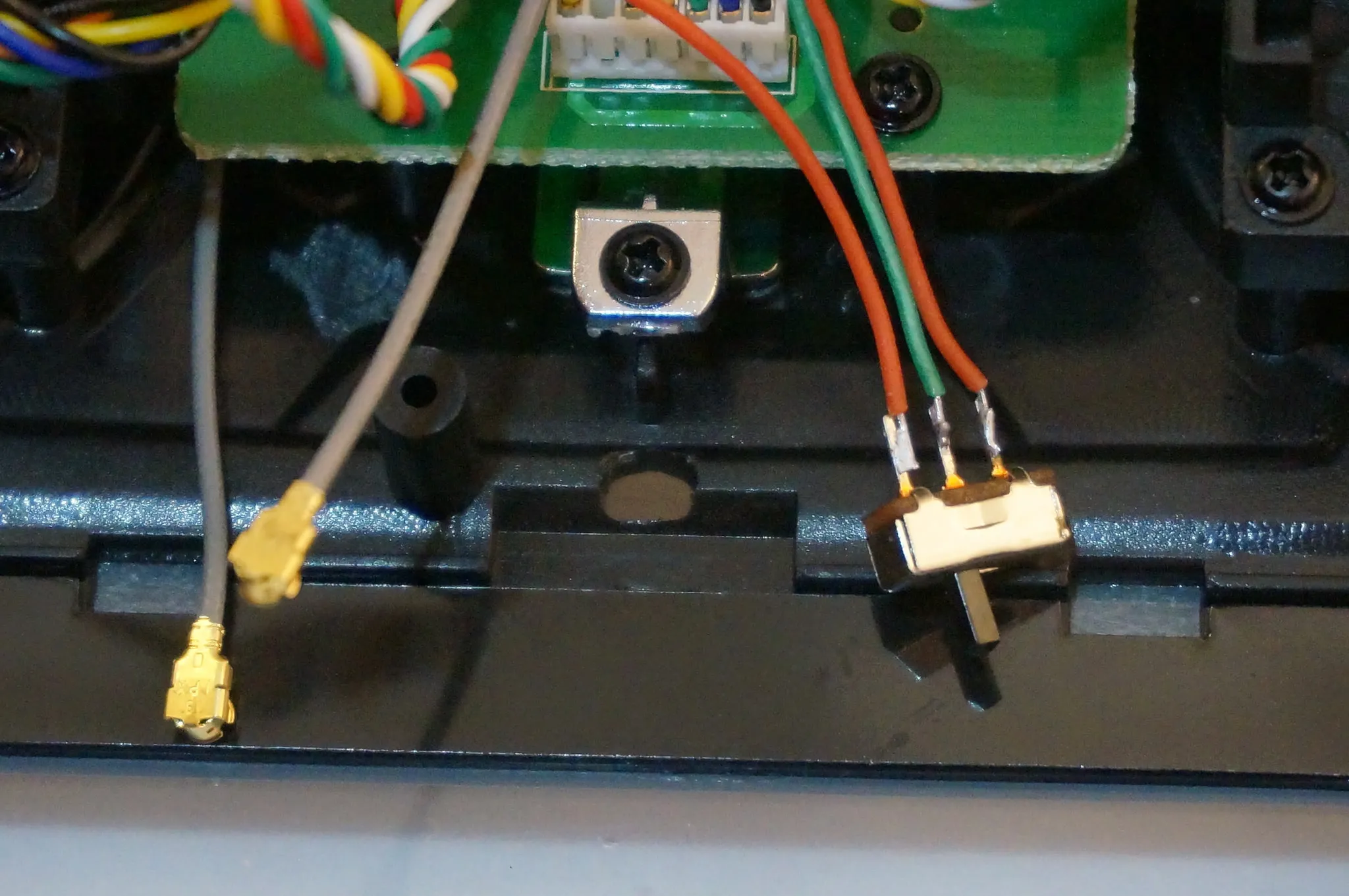
Now take the leads from the switch and wire the green wire (middle wire) to the solder blob on the 3.3v output.
Solder one side of the switch to the internal radio module.
Solder the other side to the DIY module power.
Before we re-assemble, let’s program the DIY module with our configured code.
DIY TX Module Programming
You can program the Note that your USBASP programmer should have two voltage settings. BE SURE TO USE THE 3.3v SETTING!
To program the module connect your USBASP like so, if you installed the headers on the back like I did in the section above.
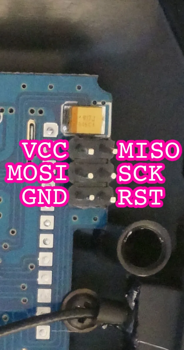
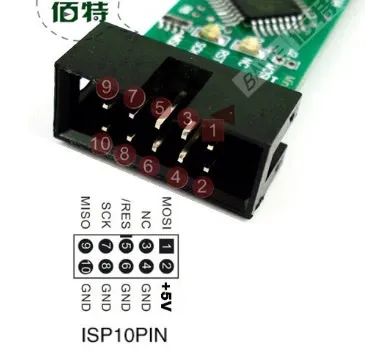
Connect each pin to it’s counterpart, MISO to MISO, MOSI to MOSI and so on.
Now that you’ve got the module connected to your USBASP, download the code from github.
Edit the _Config.h file or use mine
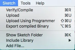
Turn the dial to 0 and pick ‘Upload Using Programmer’
Wait for the confirmation message and you’re good to go!
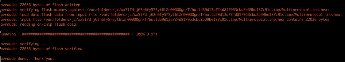
Alternatively, you can flash via the command line.
Turn on verbose logging in the Arduino studio, build the firmware and copy out the firmware build command.
Change the adapter (-c) to usbasp and flash in a terminal:
› /Applications/Arduino.app/Contents/Java/hardware/tools/avr/bin/avrdude -C/Applications/Arduino.app/Contents/Java/hardware/tools/avr/etc/avrdude.conf -v -patmega328p -cusbasp -D -Uflash:w:/var/folders/jc/xx5l7d_j63n6fy575yt6l2r00000gn/T/build39d13a724d817953cbd2b39be187c91c.tmp/Multiprotocol.ino.hex:i

avrdude: Version 6.0.1, compiled on Apr 14 2015 at 16:30:25
         Copyright (c) 2000-2005 Brian Dean, http://www.bdmicro.com/
         Copyright (c) 2007-2009 Joerg Wunsch

         System wide configuration file is "/Applications/Arduino.app/Contents/Java/hardware/tools/avr/etc/avrdude.conf"
         User configuration file is "/Users/ntsoi/.avrduderc"
         User configuration file does not exist or is not a regular file, skipping

         Using Port                    : usb
         Using Programmer              : usbasp
         AVR Part                      : ATmega328P
         Chip Erase delay              : 9000 us
         PAGEL                         : PD7
         BS2                           : PC2
         RESET disposition             : dedicated
         RETRY pulse                   : SCK
         serial program mode           : yes
         parallel program mode         : yes
         Timeout                       : 200
         StabDelay                     : 100
         CmdexeDelay                   : 25
         SyncLoops                     : 32
         ByteDelay                     : 0
         PollIndex                     : 3
         PollValue                     : 0x53
         Memory Detail                 :

                                  Block Poll               Page                       Polled
           Memory Type Mode Delay Size  Indx Paged  Size   Size #Pages MinW  MaxW   ReadBack
           ----------- ---- ----- ----- ---- ------ ------ ---- ------ ----- ----- ---------
           eeprom        65    20     4    0 no       1024    4      0  3600  3600 0xff 0xff
           flash         65     6   128    0 yes     32768  128    256  4500  4500 0xff 0xff
           lfuse          0     0     0    0 no          1    0      0  4500  4500 0x00 0x00
           hfuse          0     0     0    0 no          1    0      0  4500  4500 0x00 0x00
           efuse          0     0     0    0 no          1    0      0  4500  4500 0x00 0x00
           lock           0     0     0    0 no          1    0      0  4500  4500 0x00 0x00
           calibration    0     0     0    0 no          1    0      0     0     0 0x00 0x00
           signature      0     0     0    0 no          3    0      0     0     0 0x00 0x00

         Programmer Type : usbasp
         Description     : USBasp, http://www.fischl.de/usbasp/

avrdude: auto set sck period (because given equals null)
avrdude: warning: cannot set sck period. please check for usbasp firmware update.
avrdude: AVR device initialized and ready to accept instructions

Reading | ################################################## | 100% 0.01s

avrdude: Device signature = 0x1e950f
avrdude: safemode: lfuse reads as FF
avrdude: safemode: hfuse reads as DA
avrdude: safemode: efuse reads as 7
avrdude: reading input file "/var/folders/jc/xx5l7d_j63n6fy575yt6l2r00000gn/T/build39d13a724d817953cbd2b39be187c91c.tmp/Multiprotocol.ino.hex"
avrdude: writing flash (19048 bytes):

Writing | ################################################## | 100% 13.28s

avrdude: 19048 bytes of flash written
avrdude: verifying flash memory against /var/folders/jc/xx5l7d_j63n6fy575yt6l2r00000gn/T/build39d13a724d817953cbd2b39be187c91c.tmp/Multiprotocol.ino.hex:
avrdude: load data flash data from input file /var/folders/jc/xx5l7d_j63n6fy575yt6l2r00000gn/T/build39d13a724d817953cbd2b39be187c91c.tmp/Multiprotocol.ino.hex:
avrdude: input file /var/folders/jc/xx5l7d_j63n6fy575yt6l2r00000gn/T/build39d13a724d817953cbd2b39be187c91c.tmp/Multiprotocol.ino.hex contains 19048 bytes
avrdude: reading on-chip flash data:

Reading | ################################################## | 100% 7.50s

avrdude: verifying ...
avrdude: verification error, first mismatch at byte 0x0002
         0x04 != 0x4c
avrdude: verification error; content mismatch

avrdude: safemode: lfuse reads as FF
avrdude: safemode: hfuse reads as DA
avrdude: safemode: efuse reads as 7
avrdude: safemode: Fuses OK (H:07, E:DA, L:FF)

avrdude done.  Thank you.
Binding
I have configured my module such that the dial should be turned to the following value for each protocol:
//	Dial	Protocol 		Sub protocol	RX_Num	Power		Auto Bind		Option
/*  1 */  {MODE_FLYSKY, Flysky    , 0  , P_HIGH, NO_AUTOBIND, 0    },
/*  2 */  {MODE_FRSKY , 0         , 0  , P_HIGH, NO_AUTOBIND, 0xD7 },  // D7 fine tuning
/*  3 */  {MODE_FRSKYX, CH_8      , 0  , P_HIGH, NO_AUTOBIND, 0xD7 },  // D7 fine tuning
/*  4 */  {MODE_FRSKYX, CH_16     , 0  , P_HIGH, NO_AUTOBIND, 0xD7 },  // D7 fine tuning
/*  5 */  {MODE_DSM2  , DSM2      , 0  , P_HIGH, NO_AUTOBIND, 6    },  // 6 channels @ 11ms
/*  6 */  {MODE_DSM2  , DSMX      , 0  , P_HIGH, NO_AUTOBIND, 6    },  // 6 channels @ 11ms
/*  7 */  {MODE_CX10  , CX10_GREEN, 0  , P_HIGH, NO_AUTOBIND, 0    },
/*  8 */  {MODE_BAYANG, 0         , 0  , P_HIGH, NO_AUTOBIND, 0    },