The FluxLamp Soldering Reflow Oven
This post contains an overview and build guide for the FluxLamp soldering reflow oven.
Built with a
If you’re interested in ordering a
I do have a few prototype boards that I have assembled by hand. I can’t promise I’ll have enough for those interested, but if you would like to receive a prototype for testing and review, please fill out the form above and contact me: [email protected] with the subject line “PowerCore Review”.
If you are a manufacturer interested in producing this or derivative works, please contact me: [email protected].
I designed the FluxLamp for myself after finding that the only “inexpensive” off-the-shelf soldering reflow oven, the T962, is relatively expensive and of poor quality. For example, having to remove masking tape from inside the machine before it melts is not a good starting point.
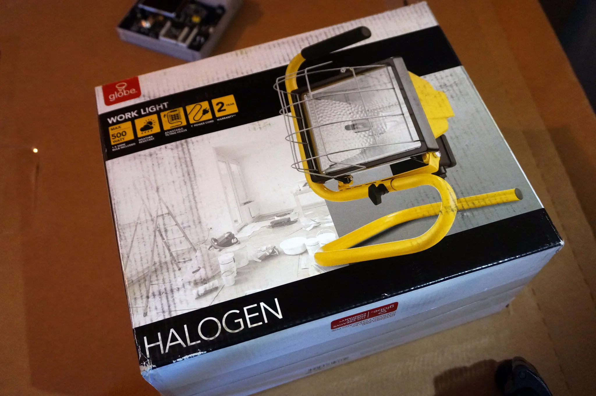
Instead of fixing the T962, I decided to build something hackable and open source from the ground up. The FluxLamp is cost-effective and easily assembled in a home workshop. It uses a standard 500W Portable Halogen Work Light as the heater, since it is cheap and readily available. The lamp is set on the table face down over the PCB to be reflowed. There is also an optional fan for faster cooling. The only limitation of the FluxLamp is its relatively small size—up to about 100mm x 120mm working area. This should be plenty of space for my projects, and I hope it will work for you as well. Depending on feedback from the community, I have explored manufacturing a housing with a dual-lamp configuration and more working area. This could be available in the future.
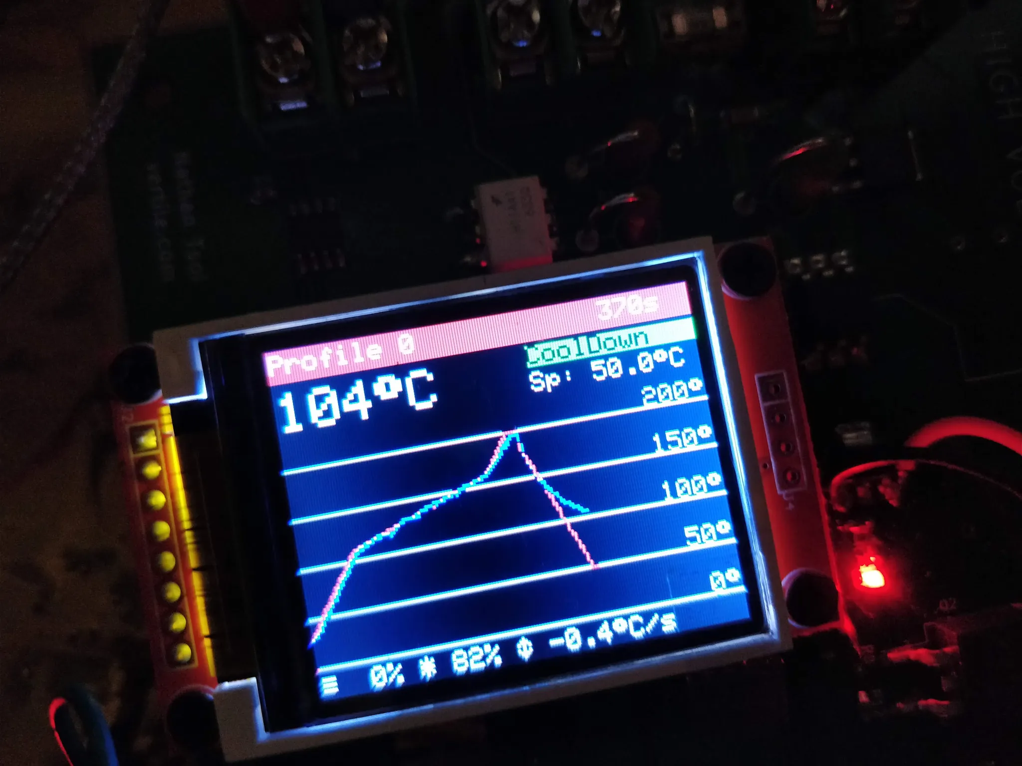
I was skeptical the lamp could provide adequate heating, but it does the job just fine. Here you can see the k-type thermocouple added to the lamp.
Here is an example soldering reflow profile:
Assembling prototypes by hand takes quite a while, so if the Indiegogo campaign is successful, I’ll order a bunch of boards from a manufacturer for the community. Best to let the machines do this, but it will take enough interest from the community to enable economies of scale (please fill out the interest form):
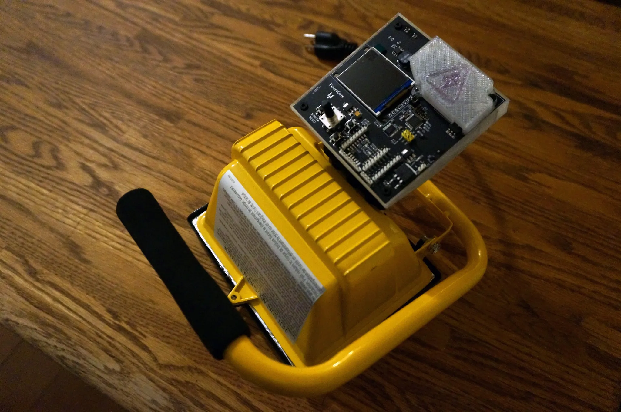
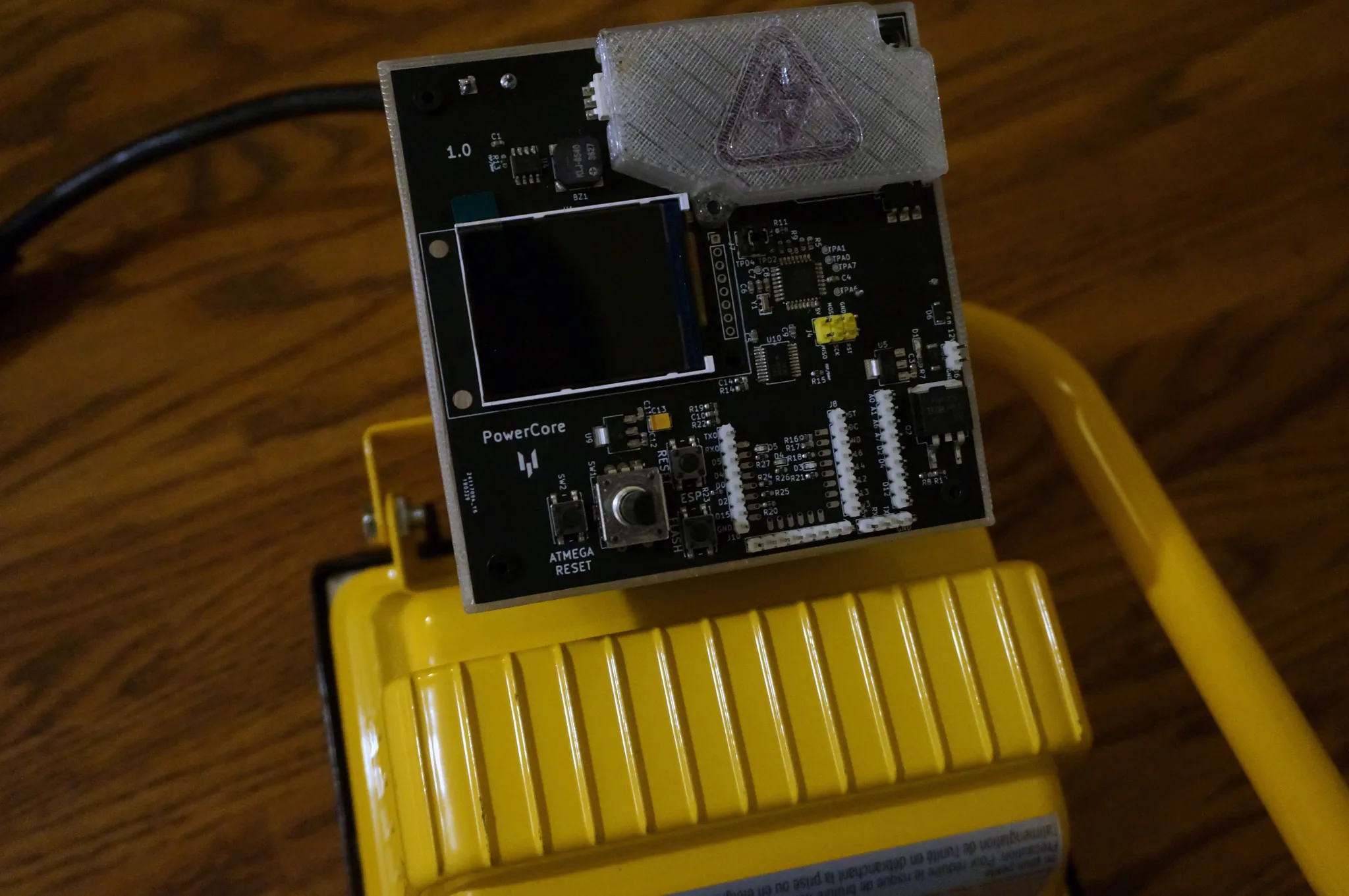
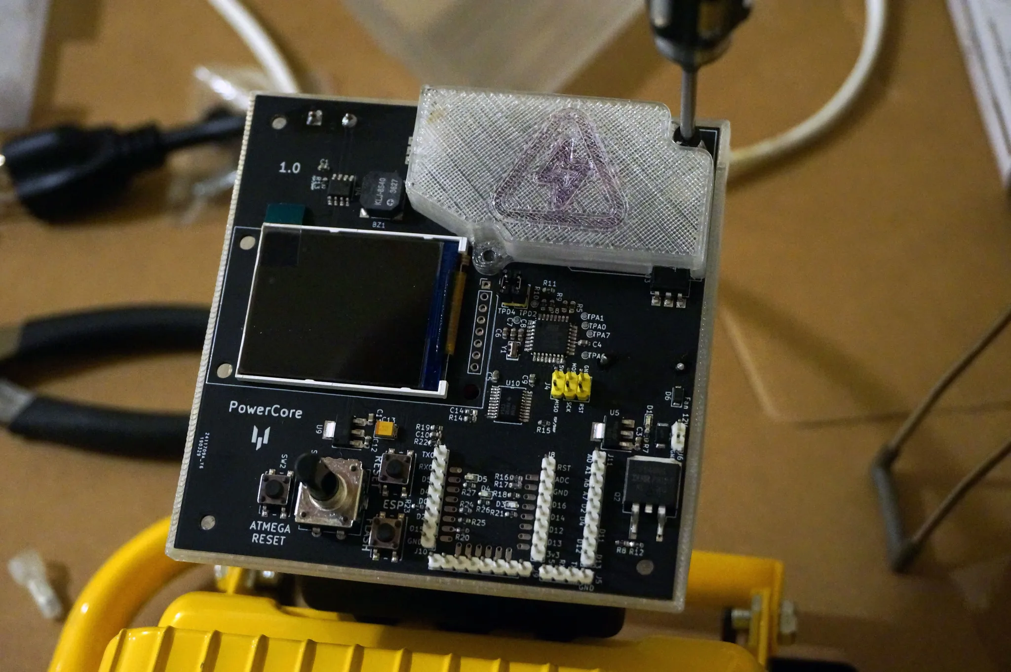
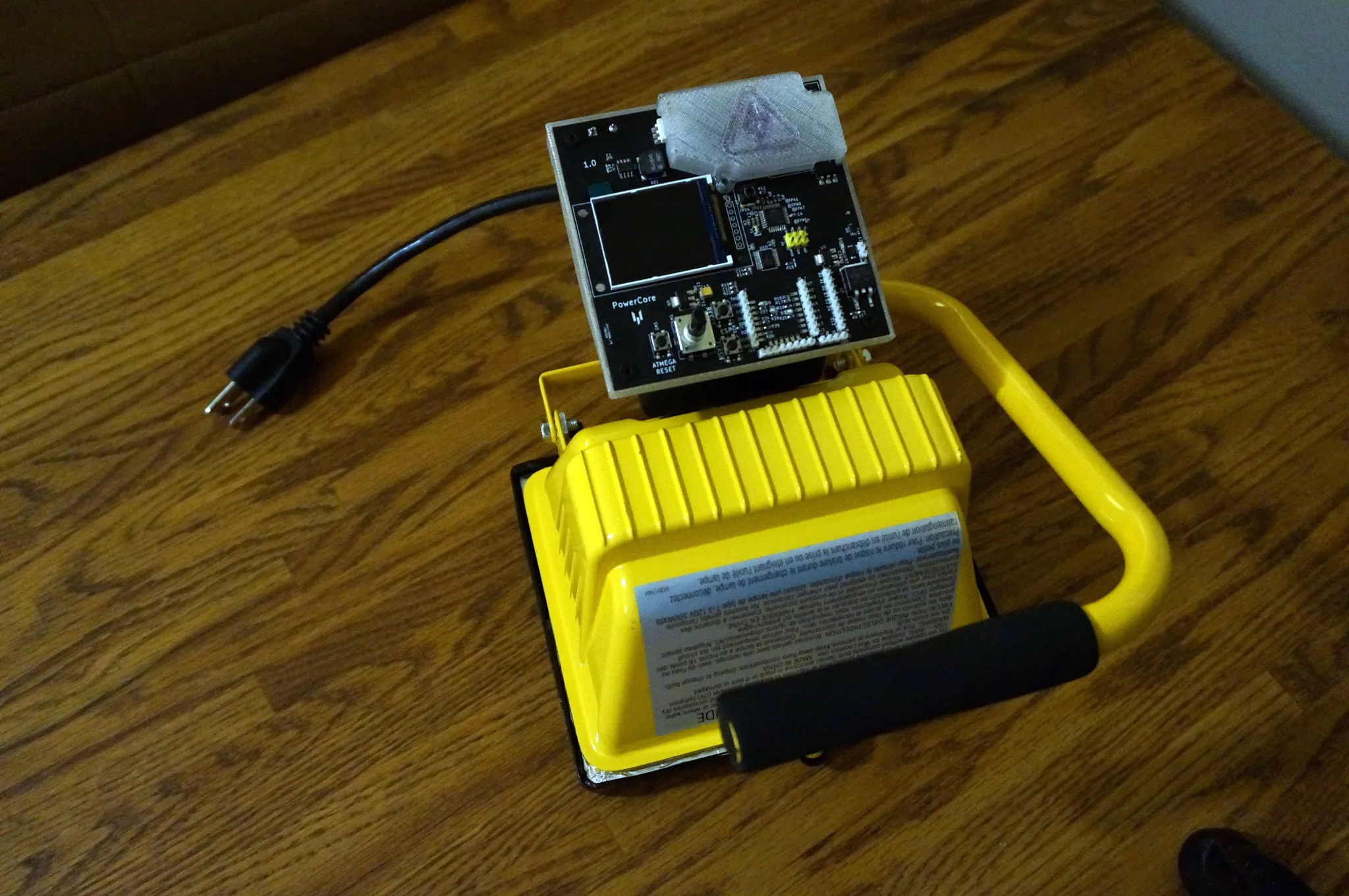
On top of this halogen lamp is a 3D printed box with the control unit that you can order when the Indiegogo launches or print yourself from the designs on Thingiverse.
It runs an ATmega328p (Arduino) microcontroller.
There is a rotary encoder for input. For output, there is a small buzzer and an LCD panel. This prototype is mounted in a flat case for testing on my desk (without the lamp).
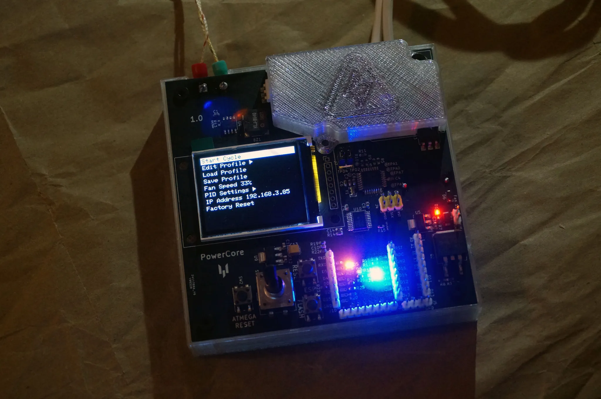
I have integrated a power supply into the main controller, so the whole thing only needs 1 (AC) power cord and no external DC supply.
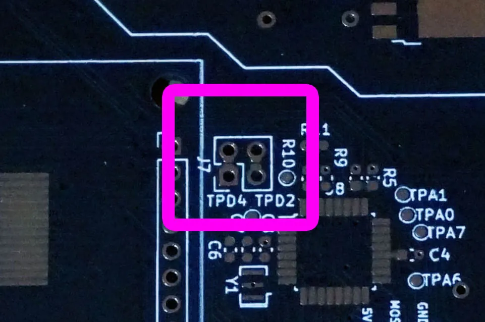
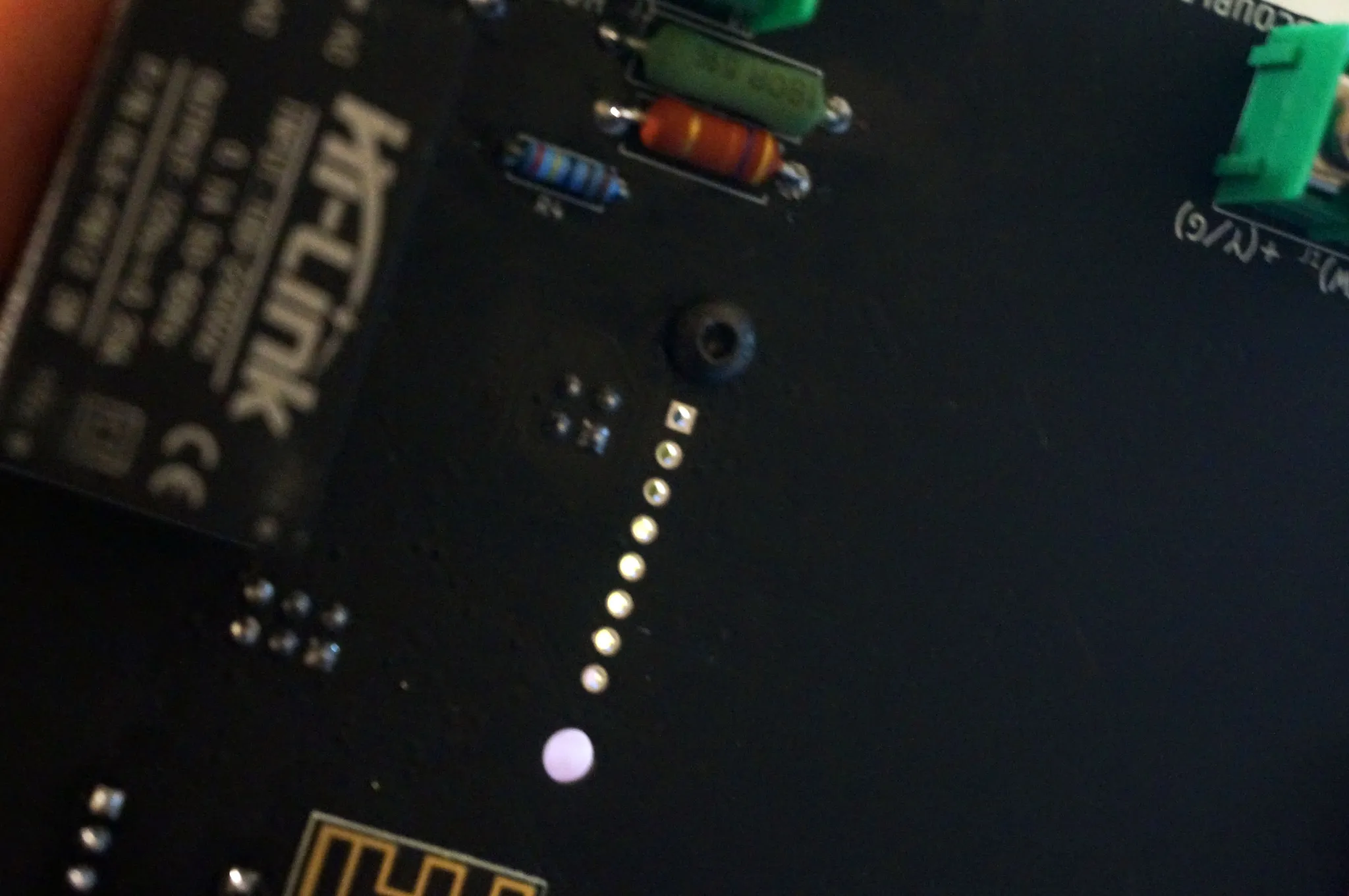
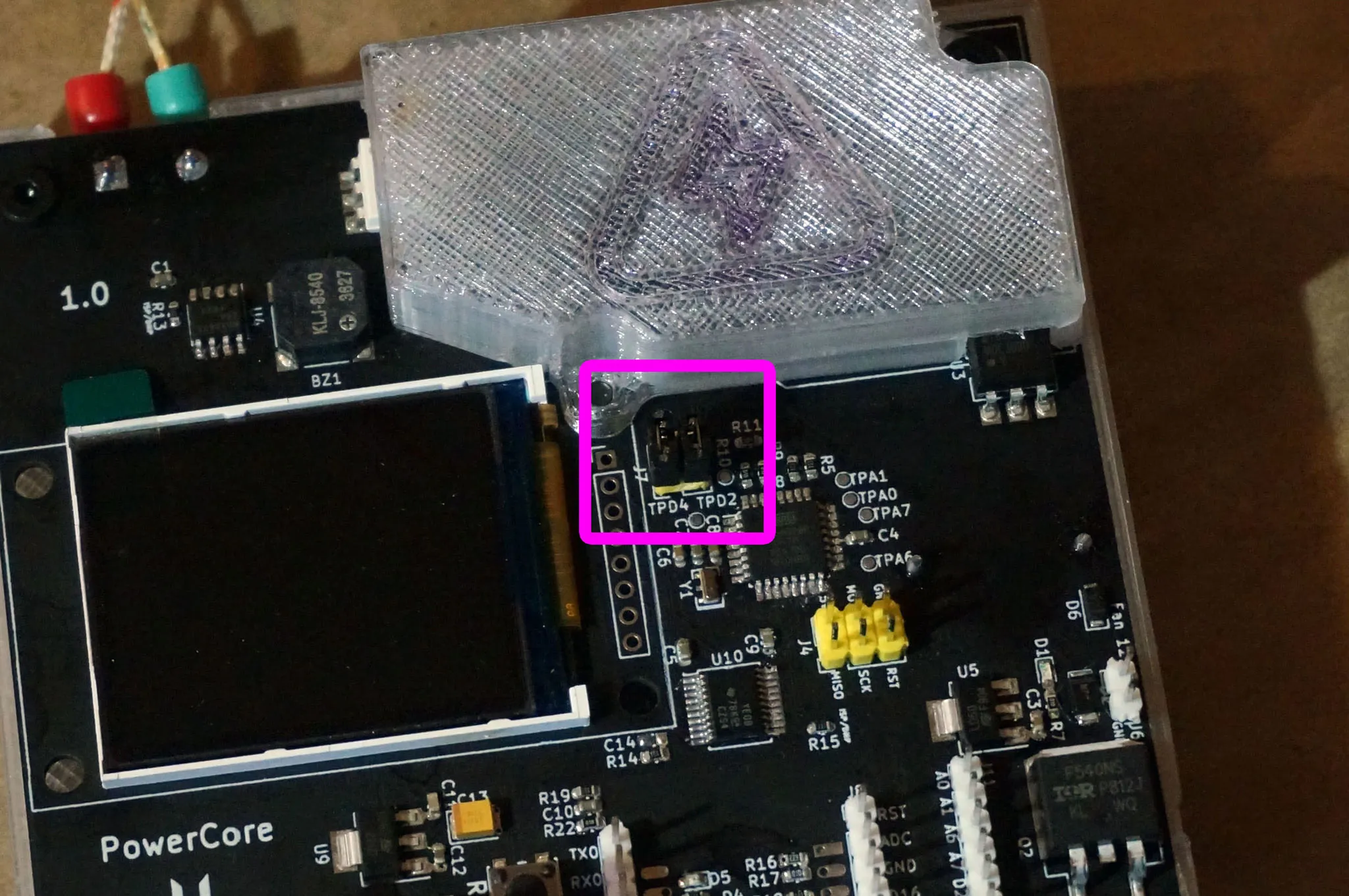
I’ve also added an ESP8266, which will enable firmware updates without an ISP programmer or USB-UART adapter. The WiFi module shares a serial port with the ATmega328p, allowing WiFi control. J7 connects the ATmega328p serial port to the ESP8266 via a level shifter. It is designed for 2.54mm headers or a solder bridge, depending on whether you want to be able to easily connect and disconnect the UART connection.
You can read more about the PowerCore design in the
Design and Development
Being a software engineer, the hardware design process was relatively new to me, but inspired by James Bowman, I decided to design some hardware! Instead of starting with the BGA chip I wanted to use in a new camera design, I thought it might be a bit more prudent to begin with some QFP/QFN devices.
I used KiCad 5 to design the PCB. I did explore using Eagle, Altium, and OrCad as well. My expectations were low for KiCad, but after working with KiCad 5, I am very impressed.
Parts
If you’re building one of these yourself—which I highly recommend—you’ll need to order a control board. I’m getting ready to launch the Indiegogo campaign, so sign up here if you’re interested and I’ll let you know when it launches: https://goo.gl/forms/NL6RoZNbVZ8R6ZUR2.
I think there are several different ordering options, from fully assembled to partially assembled to raw PCBs. One of the advantages of buying an assembled board is that it will come tested and loaded with a bootloader and firmware, possibly saving a bit of headache. For the full experience, though, assembling your own board from scratch can be a thrilling experience! A good middle ground might be getting a board that has been reflowed with the SMD components and the through-hole components supplied in a kit. On the form, there is a place to mark which option you are interested in.
-
A 500W Portable Halogen Work Light. I’ve ordered this exact model myself and tested with it. It works great!
-
The 3D printed enclosure, which may be available on Indiegogo when the campaign launches and is freely available on Thingiverse.
-
5x 3mm x 5mm screws (3mm diameter) to hold the PowerCore in the mount.
-
An optional 40mm x 40mm 12V Fan, for cooling down the board.
The following are optional and not necessary if you have an assembled board:
If you’ve got a new ATmega328p chip without a bootloader, you’ll need a USBasp to flash the bootloader once.
If you have a brand new ESP8266 without the PowerCore firmware, you’ll need a UART to USB converter. I like CP2102-based devices.
Build Guide
With an assembled PowerCore and 3D printed mount, building your own soldering reflow oven is easy!
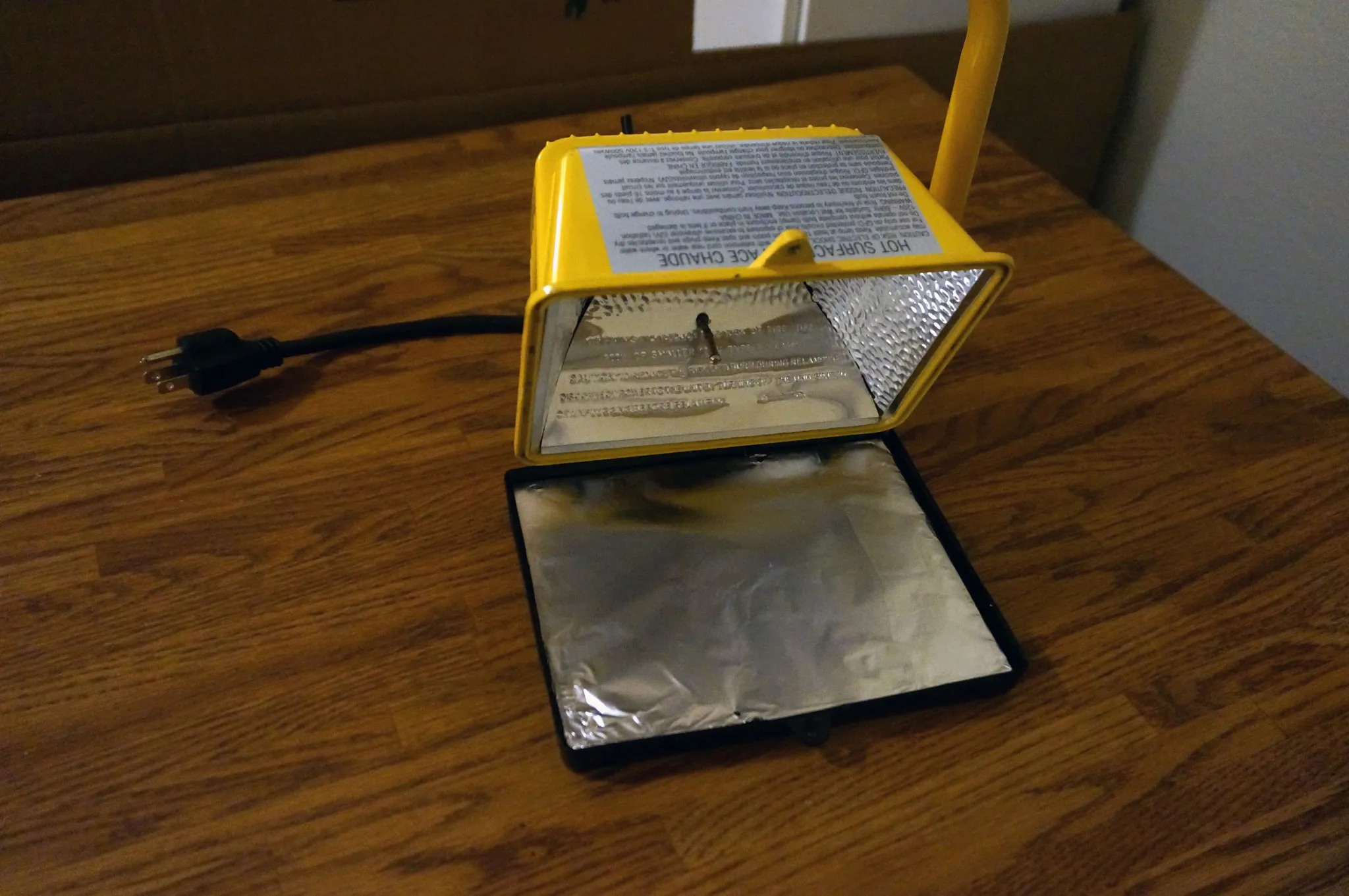
Open up your new 500W Portable Halogen Work Light.
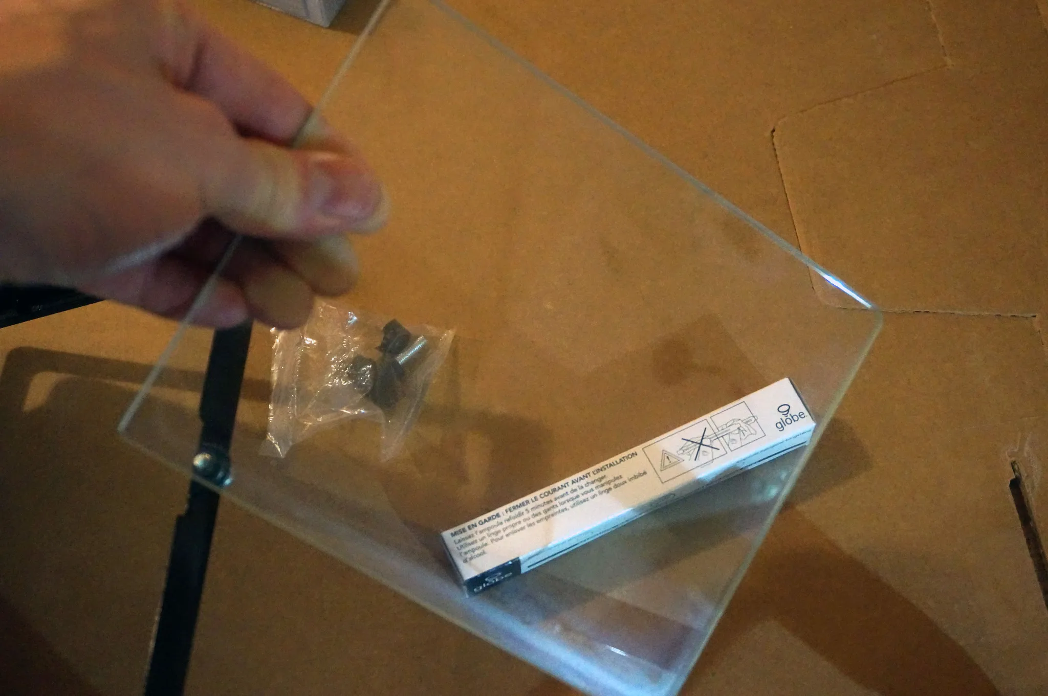
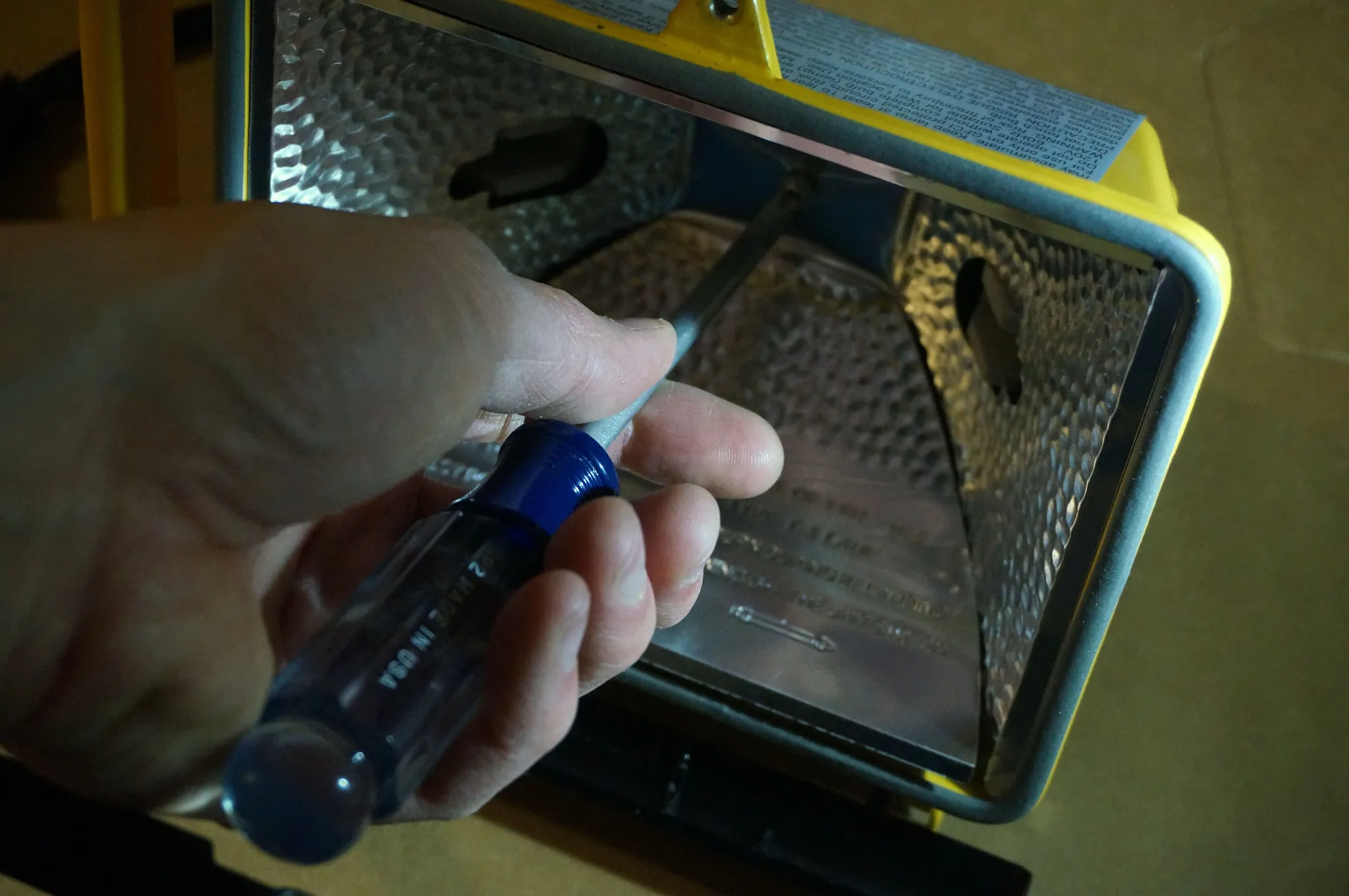
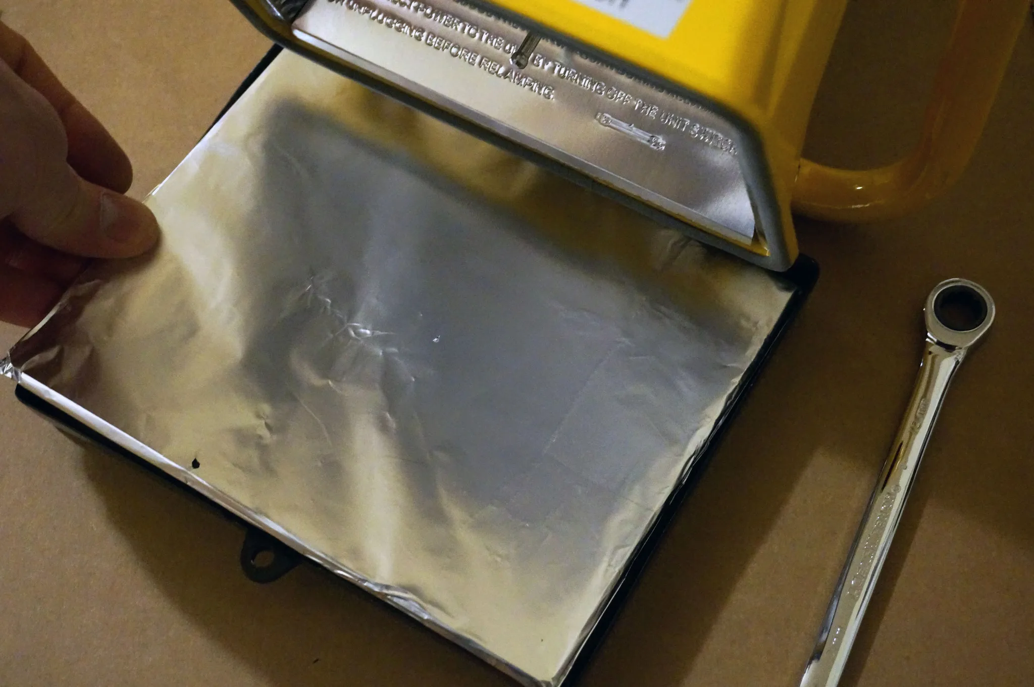
Remove the glass.
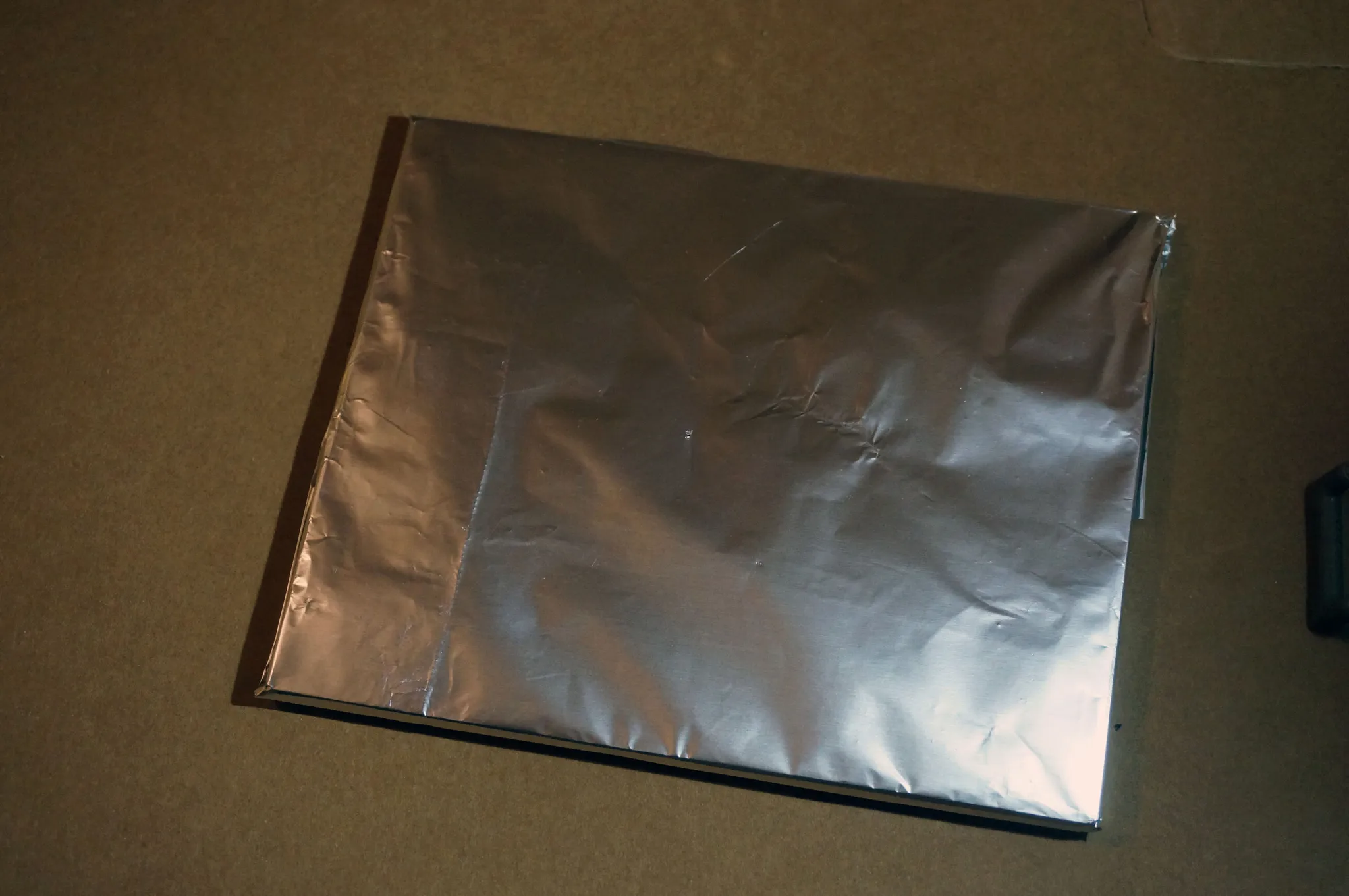
Cover the glass with aluminum foil.
Remove the back cover of the electrical housing.
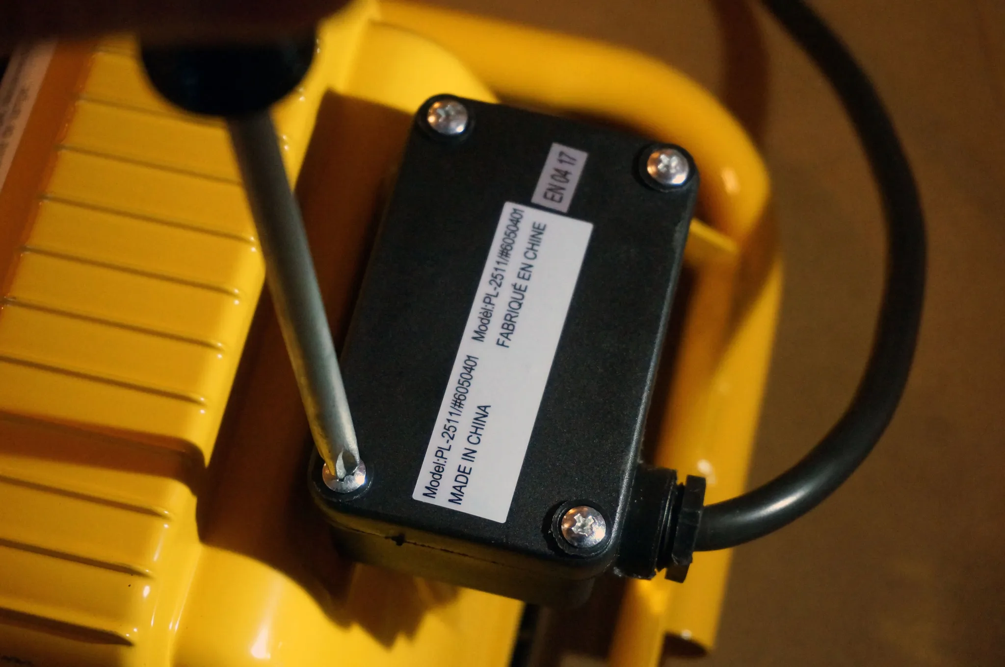
Remove the screws holding the housing to the lamp. This will make it easier to install the thermocouple.
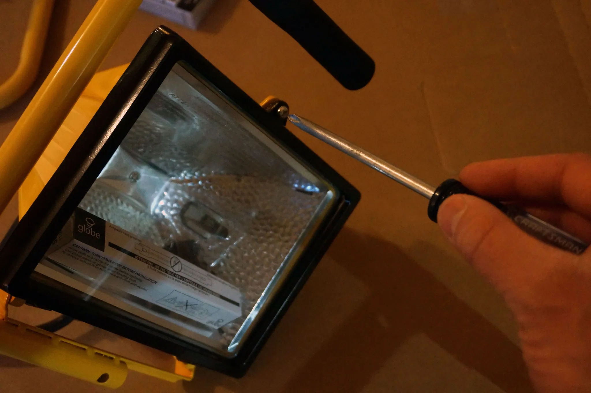
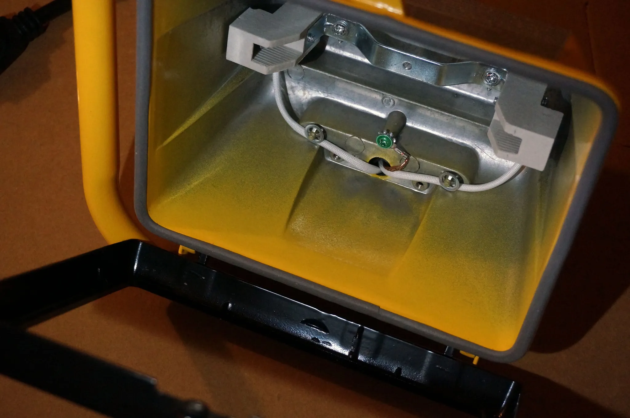
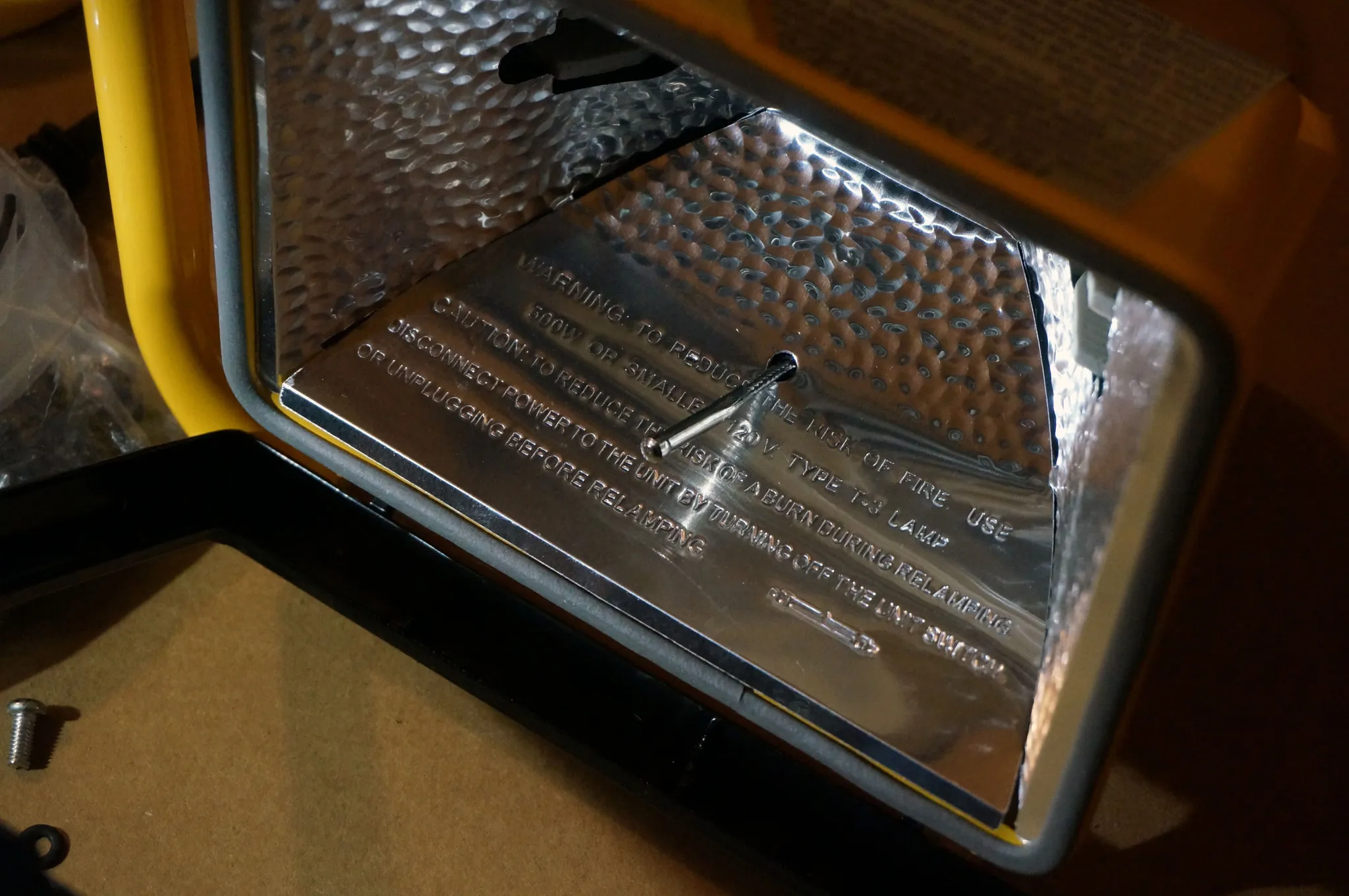
Remove the screw holding in the reflector.
The inside of the lamp looks like this:
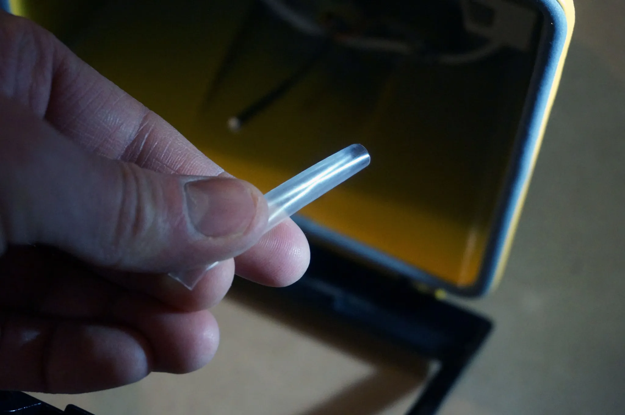
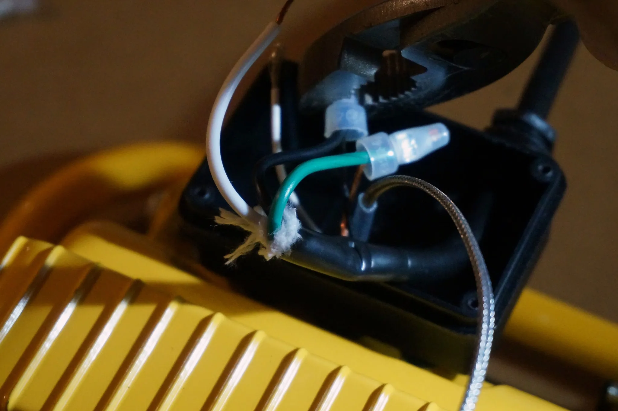
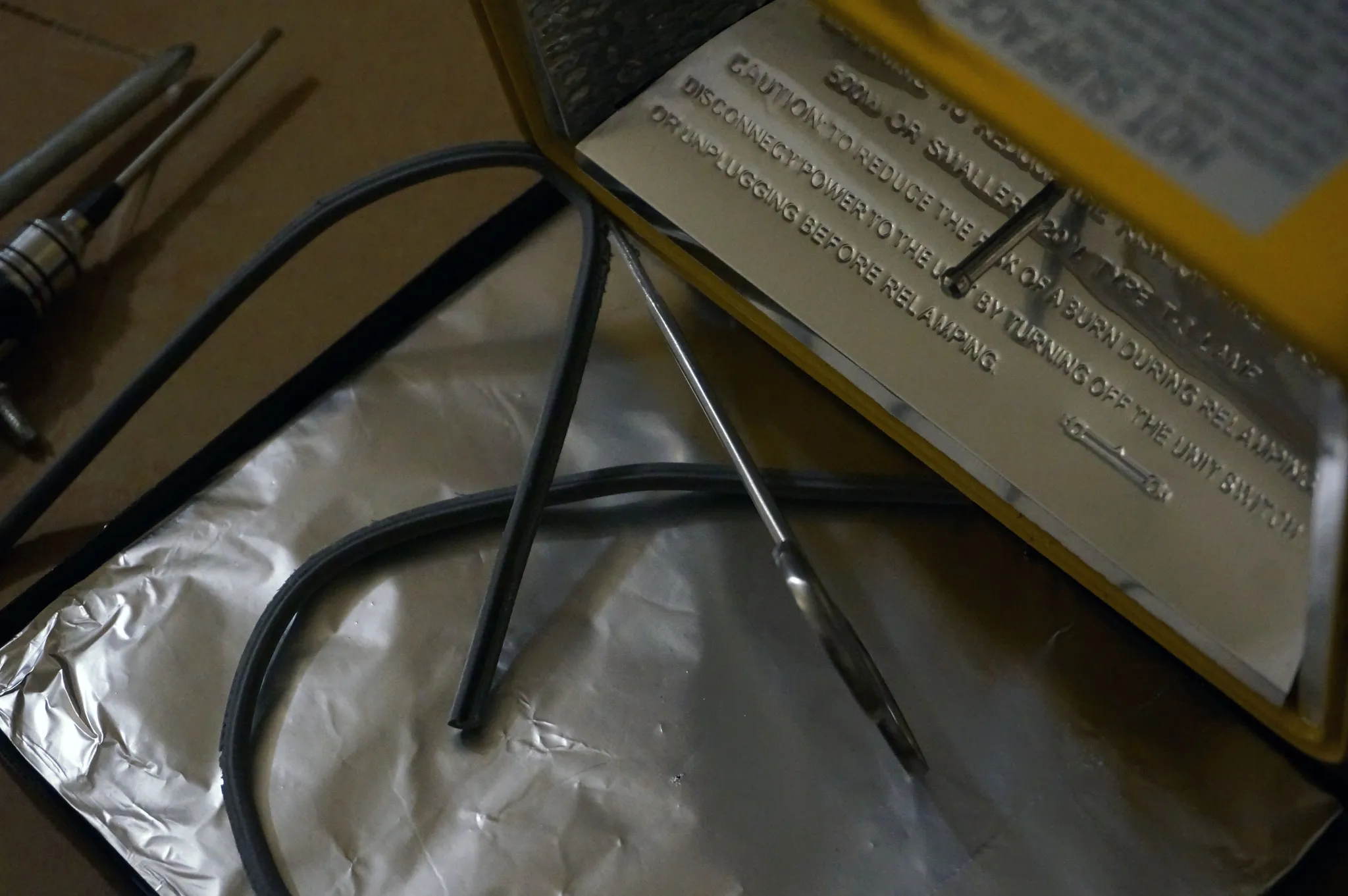
Crimp the thermocouple housing down so you can slide back the nut.
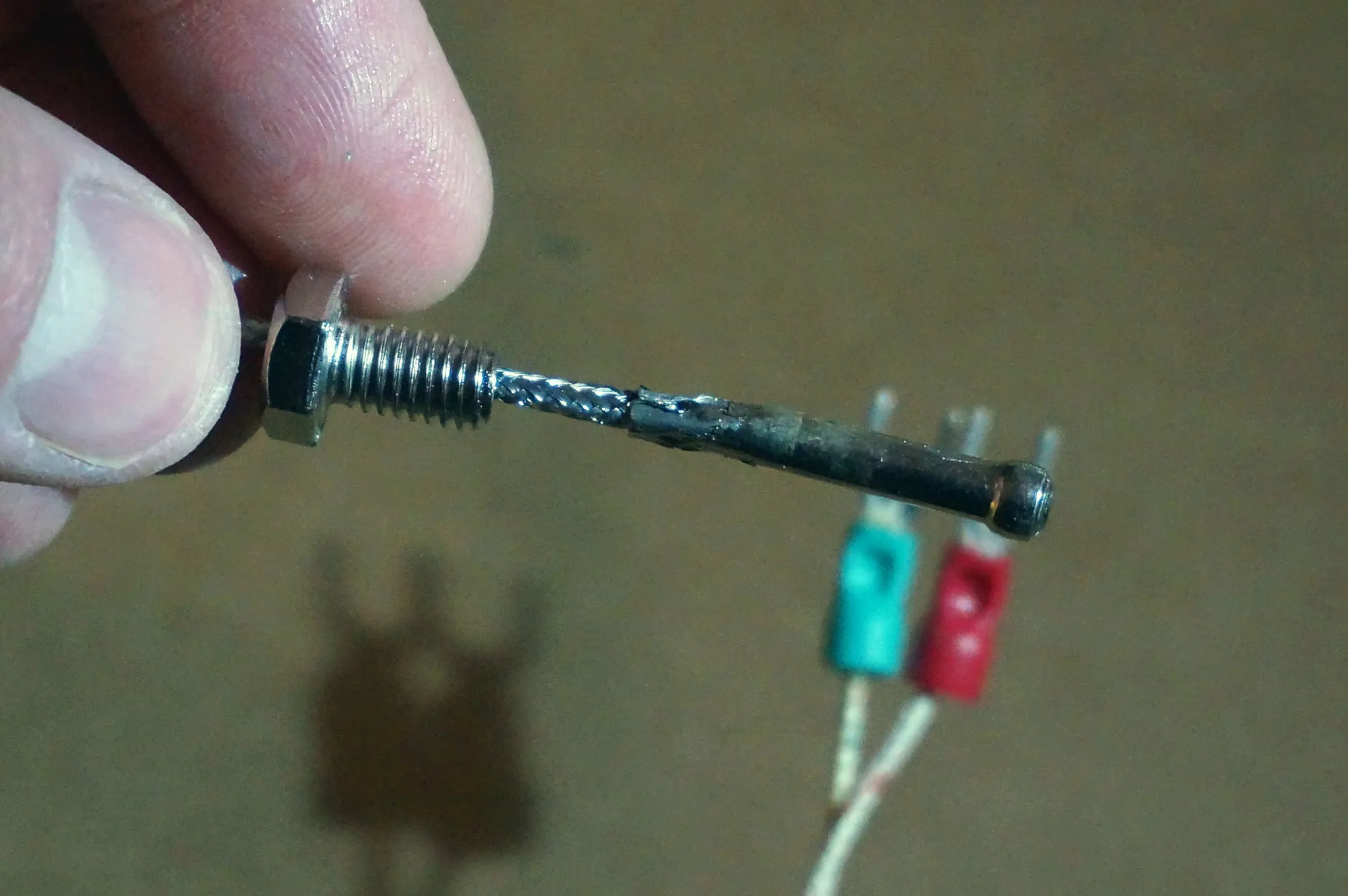
Slide the thermocouple through the plastic case into the lamp body. It will be a tight fit, but it will fit.
Since the thermocouple casing is metal, I want to make sure it doesn’t cause any shorts. I put a short piece of heat shrink tubing (I’m using Polyolefin, which can withstand higher temperatures than PVC heat shrink tubing) on the thermocouple lead.
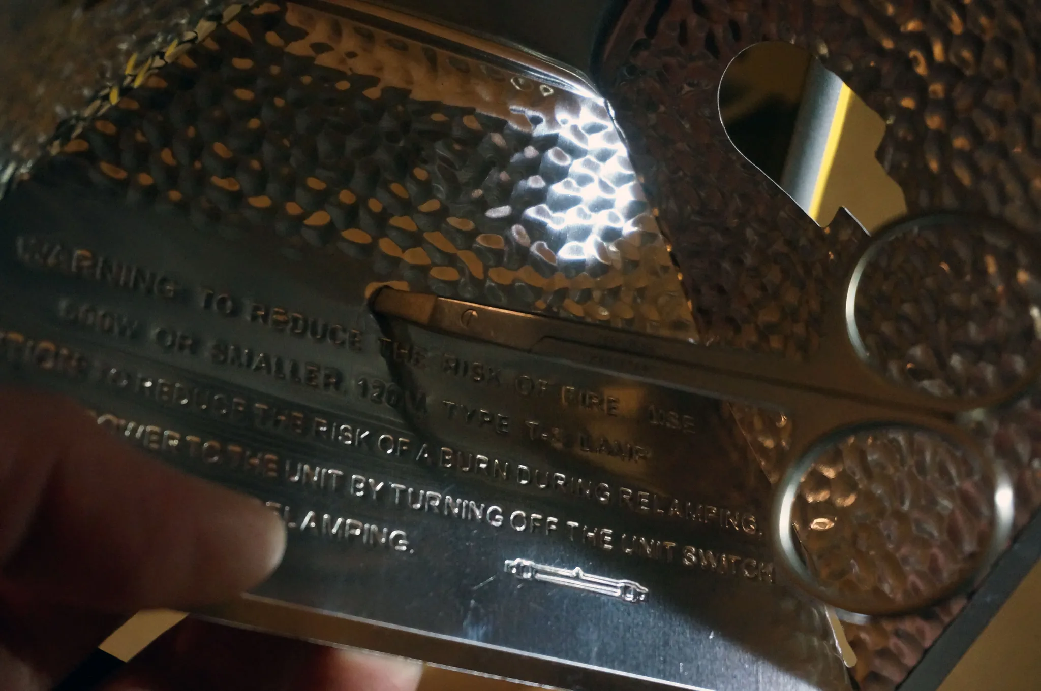
Poke a hole in the reflector using something sharp (I used some small scissors).
Pull the thermocouple back up a bit and re-install the reflector. I tried to position the end of the thermocouple as far down as possible, but not so far that it will touch a PCB being soldered. This doesn’t need to be exact, as you can always bend it out of the way later.
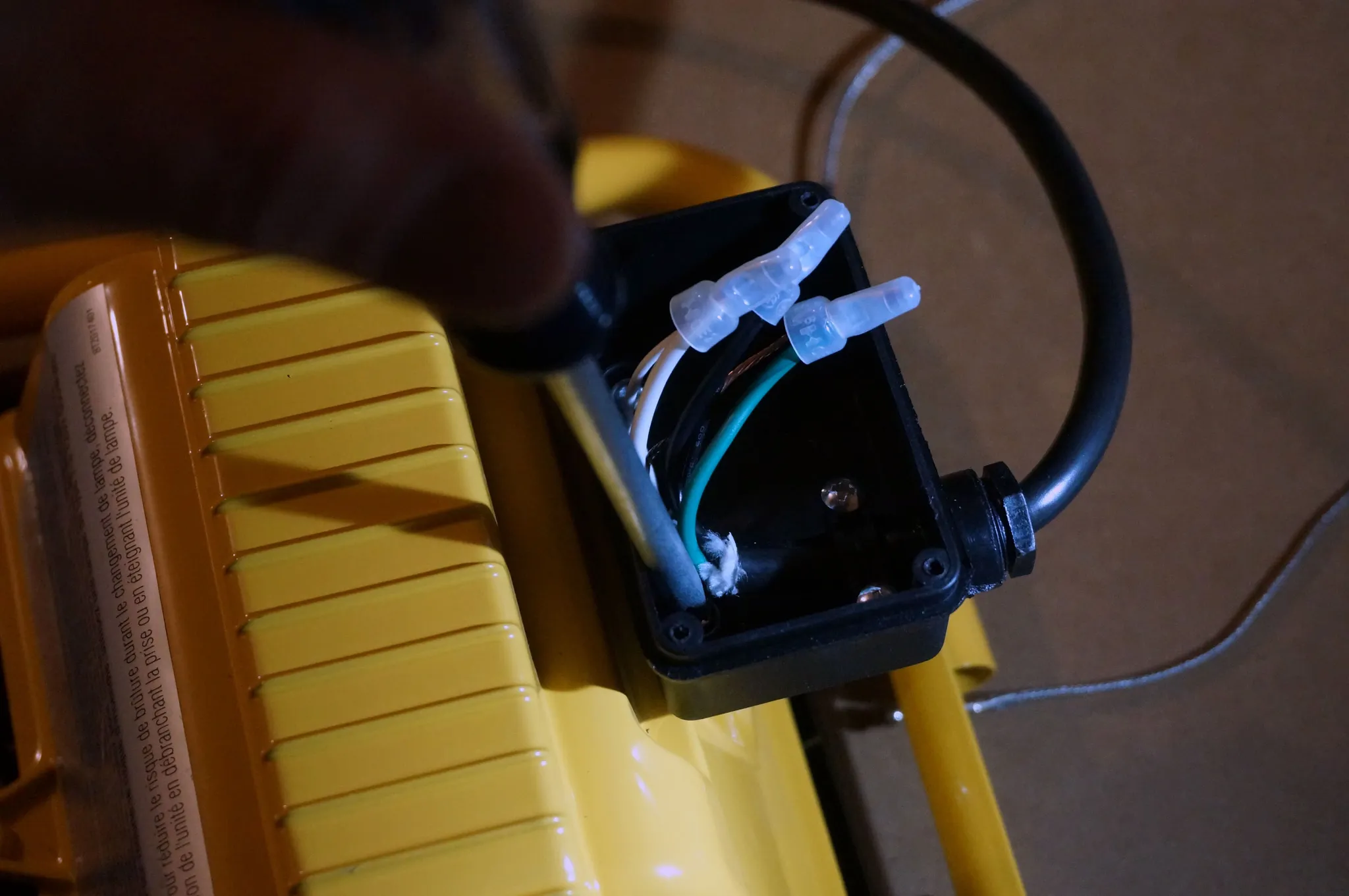
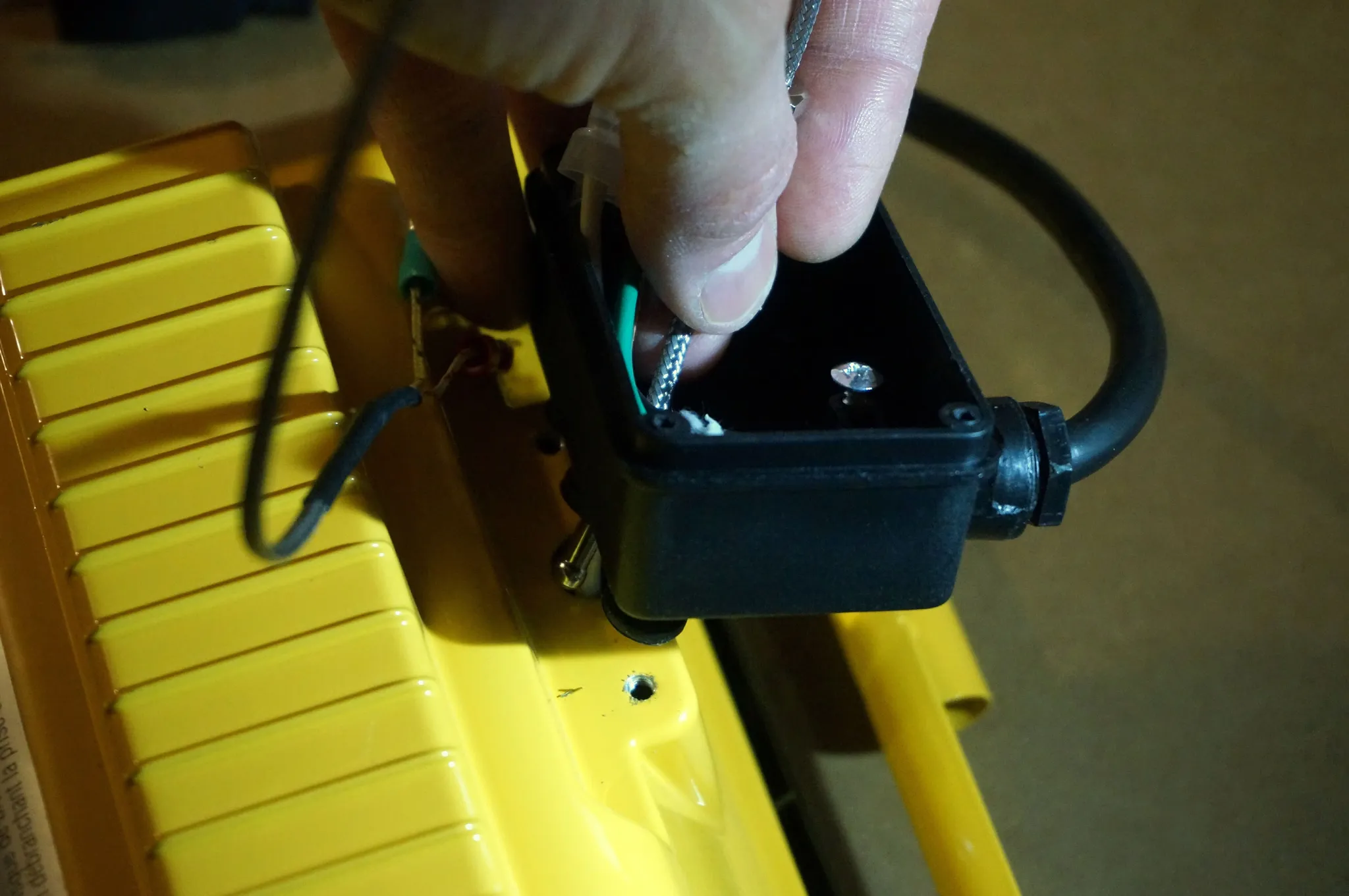
Loosen the screws holding the power cable.
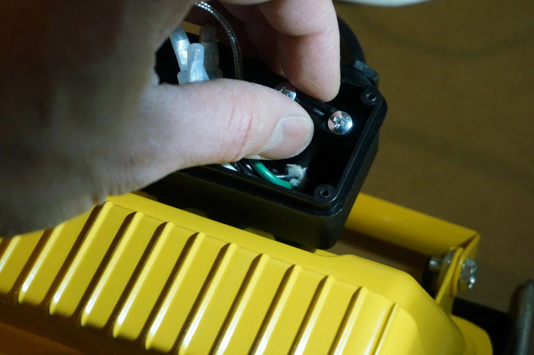
Loosen the big plastic nut holding the power cable.
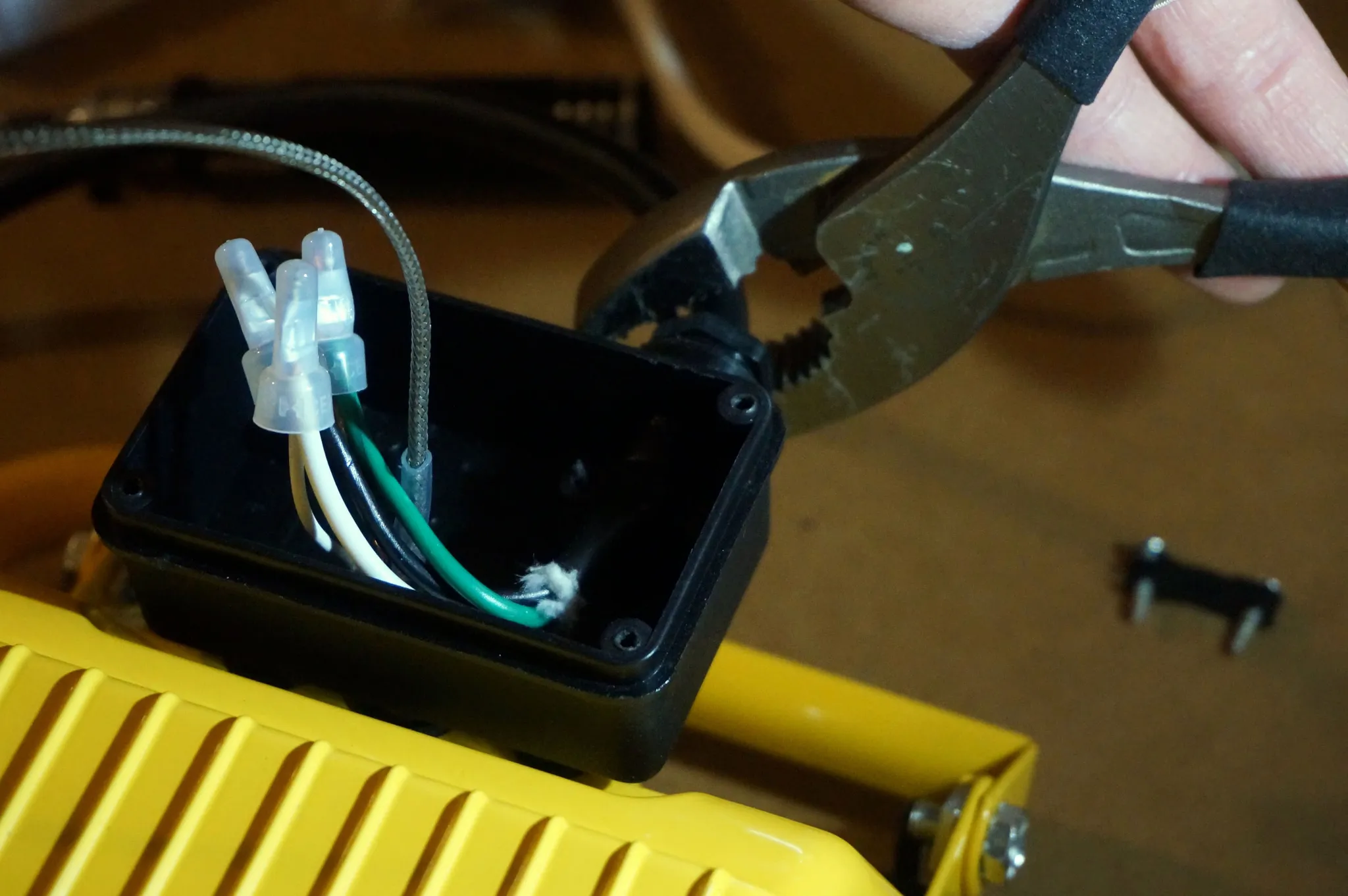
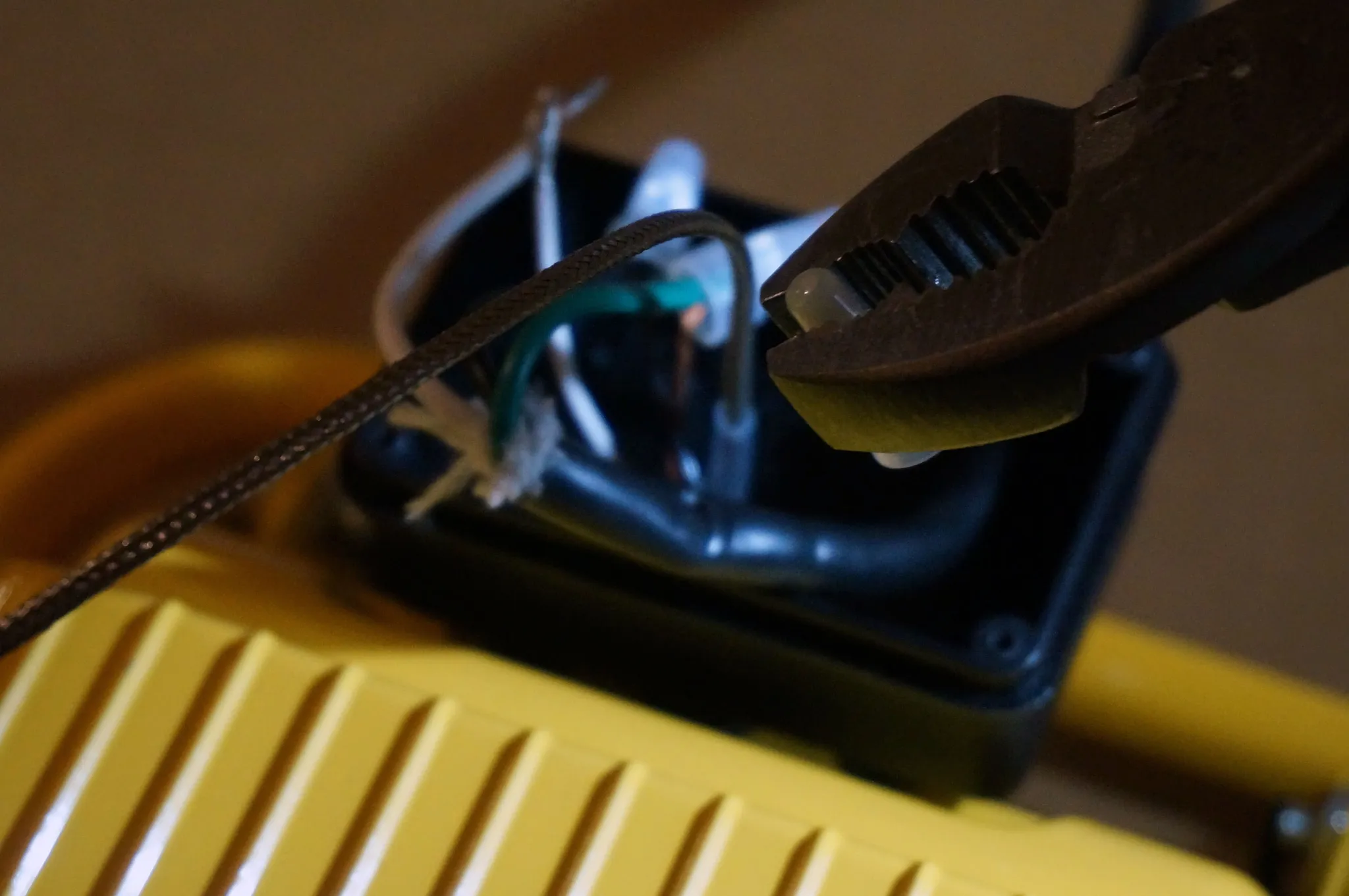
The wire crimps can be removed with a pair of pliers. Just press lengthwise, opposite the direction of the original crimp, to re-open.
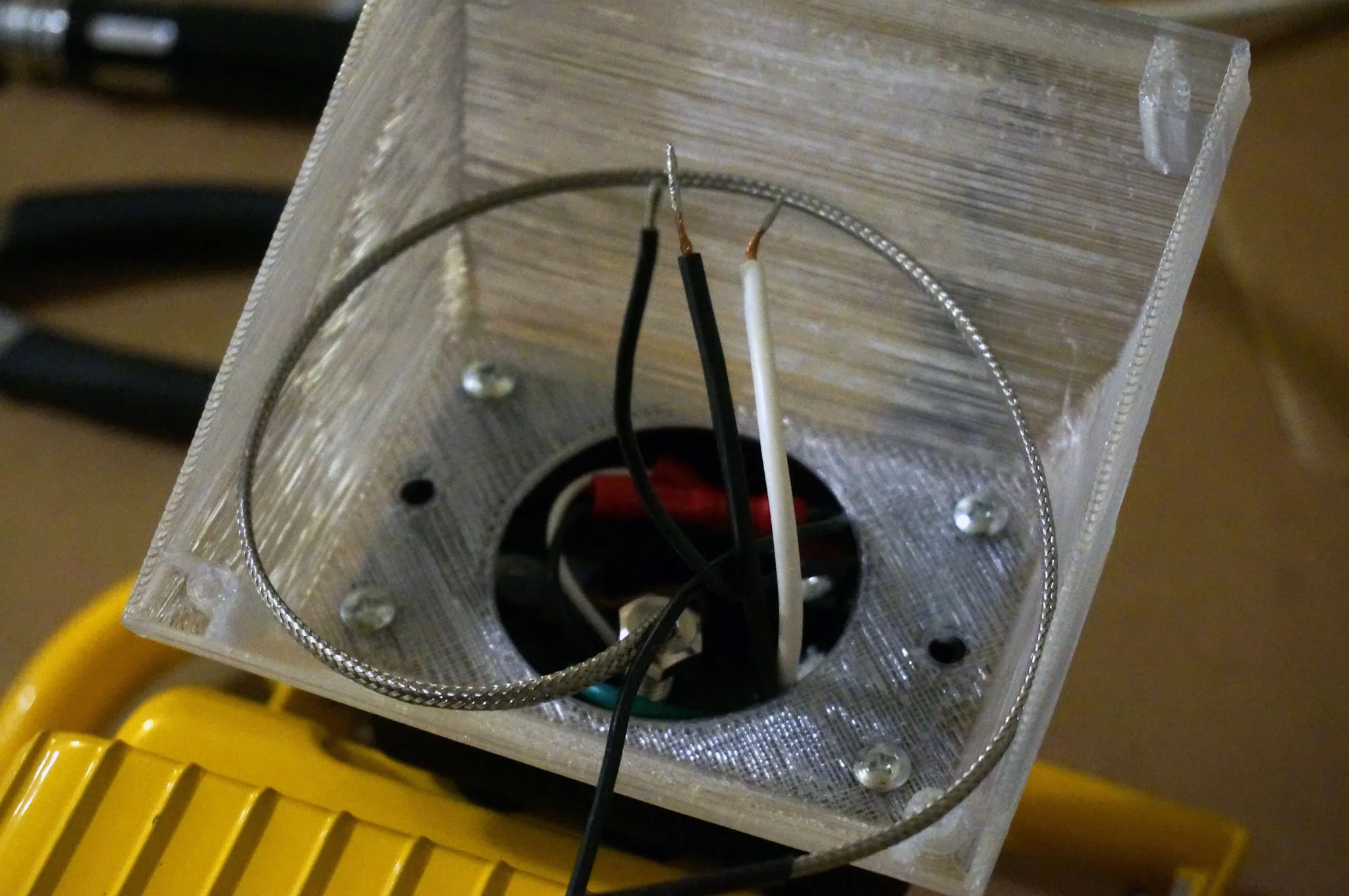
Now all the wires except the bare copper ground wire should be free, so grab your 3D printed mount, set it on the black plastic wire box, and pull the extension cord back a bit until the wires reach into the corner of the 3D printed mount. Route the ground out of the way. If the power leads don’t reach, use a knife to cut back a bit of the power cord casing.
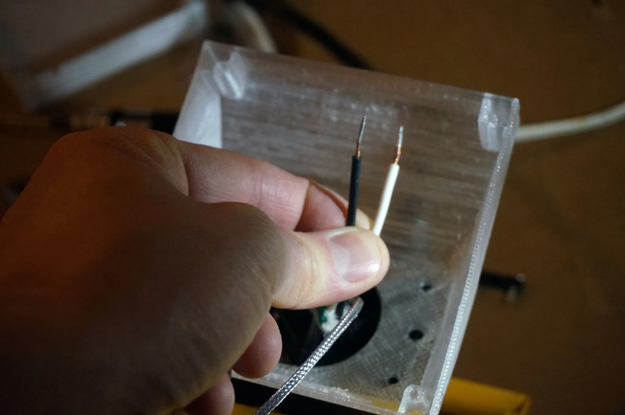
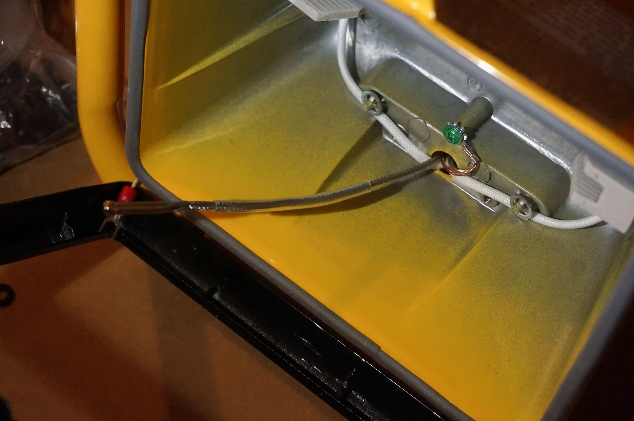
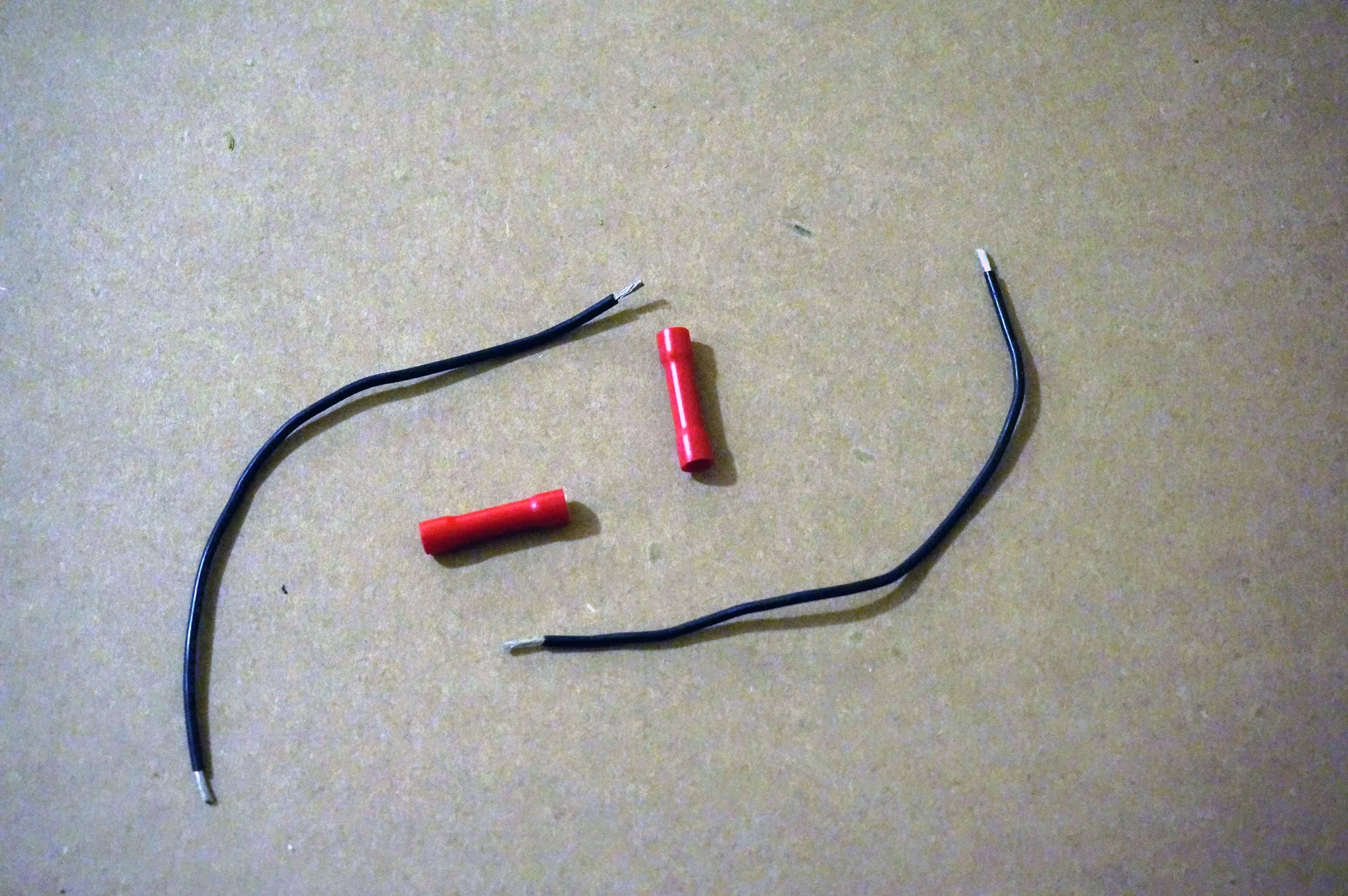
You’ll need a couple of short leads to lengthen the wires for the lamp fixture. You can re-use the crimps you loosened earlier or grab some new ones (I used some new ones, but either will work fine).
Use the original screws from the black plastic cover to secure the new mount. With the extensions installed on the lamp side of the wiring and the power leads adjusted for sufficient length, it should look like this:
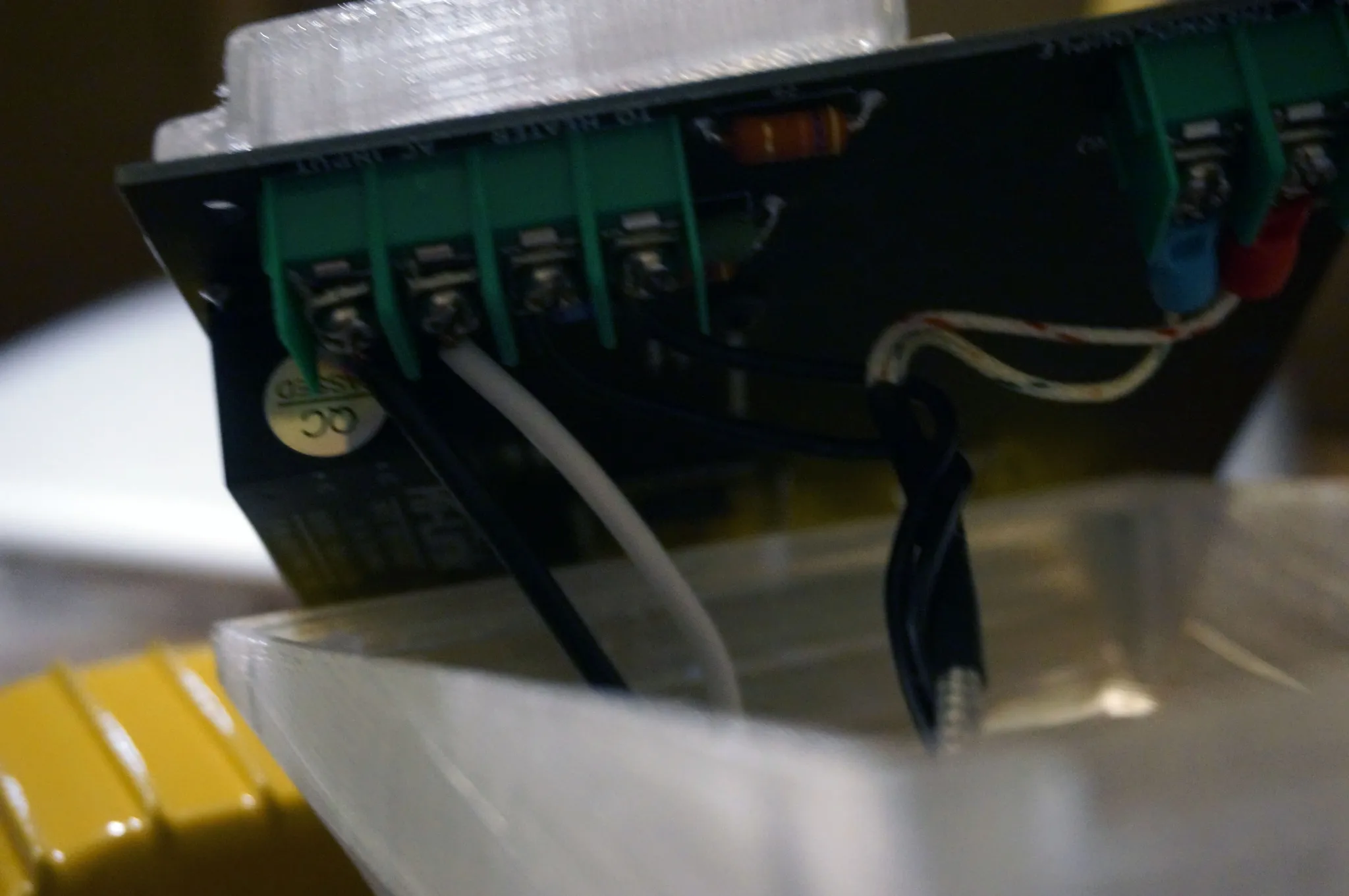
Time to prep the board for installation by adding the high voltage cover to the front.
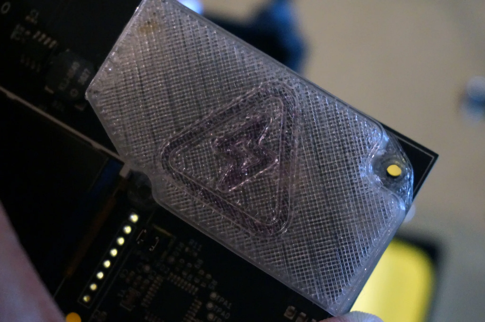
There is one 3mm screw that holds this part on. The screw goes in the back.
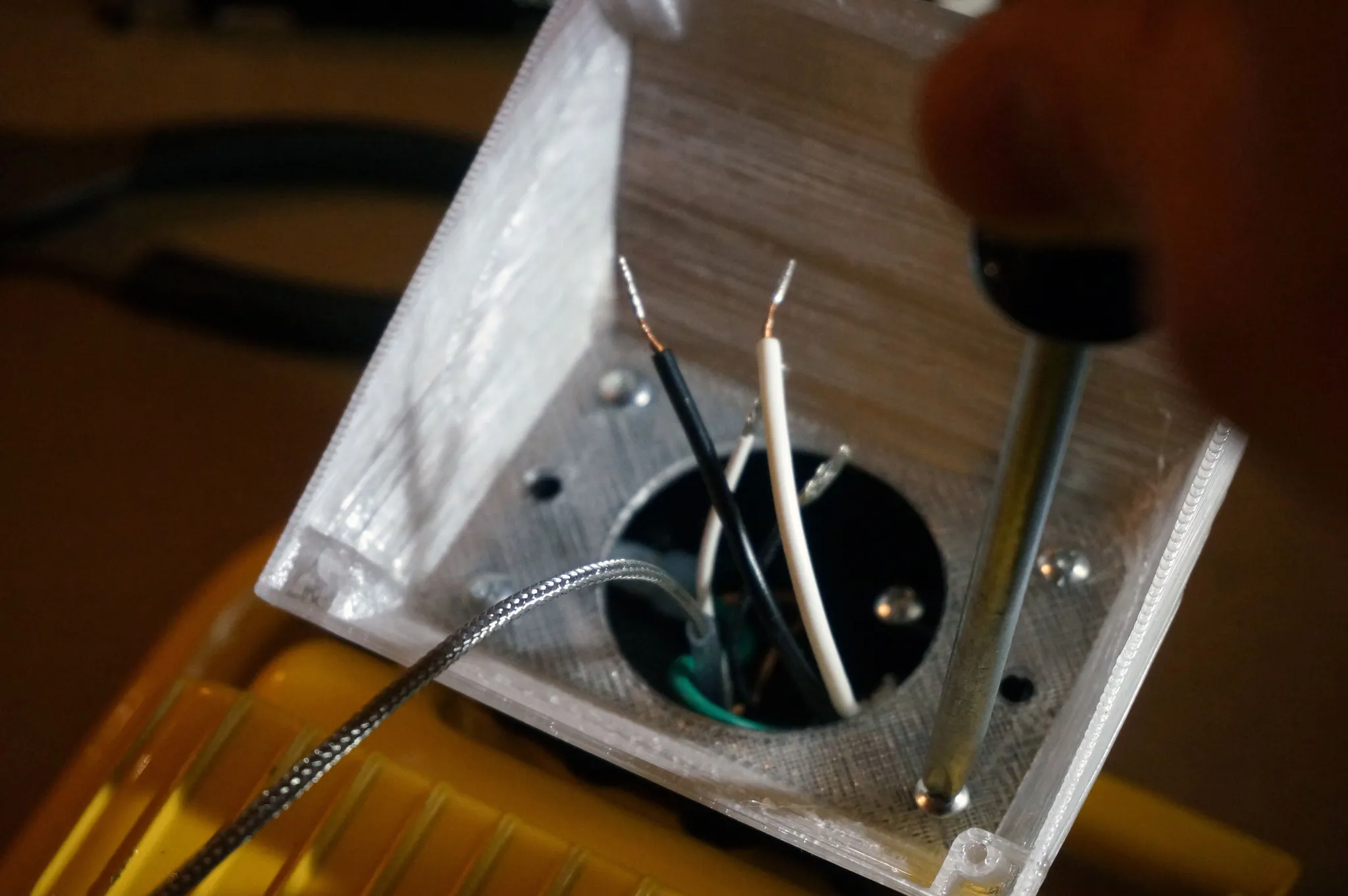
Now we can wire up the board. Install the thermocouple. The board is labeled correctly, but I noticed some k-type thermocouples I ordered had the colors on the leads switched. If the temp goes down when it should be going up, the leads are on the wrong way. It doesn’t hurt the sensor to just try one way, and if it’s backwards, switch it.
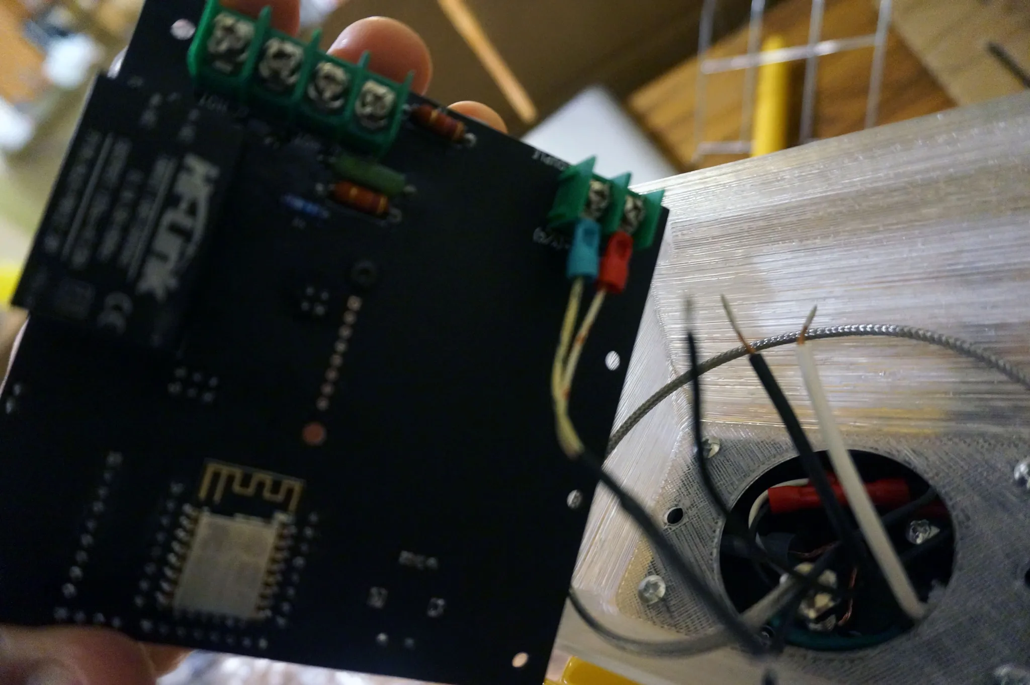
Attach the (lengthened) leads to the lamp.
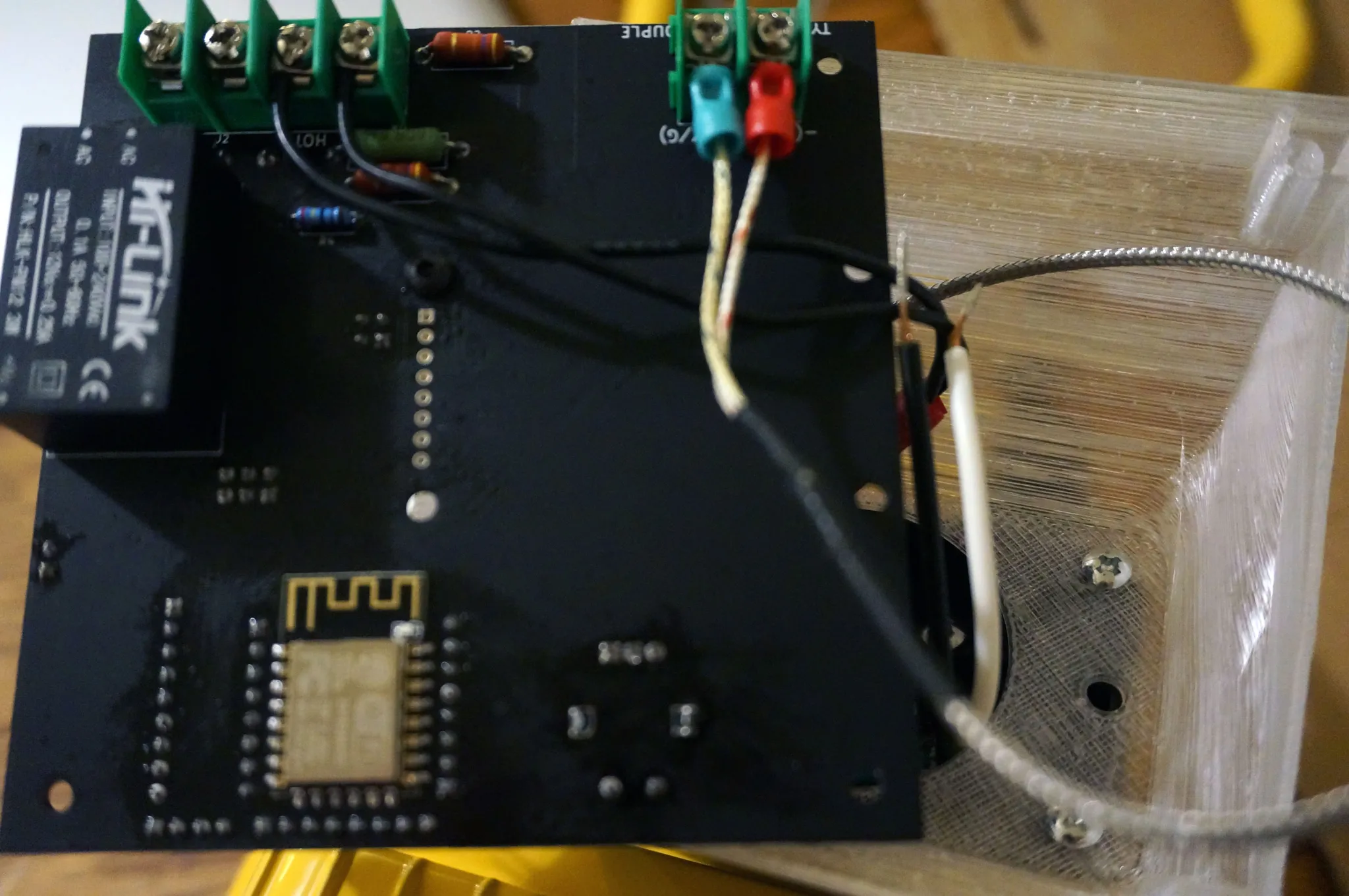
Finally, attach the leads to the power cable. These should just fit, so it’ll be a bit weird holding everything in the right place as you tighten the screw terminals.
Put the last 4 screws in to hold the PowerCore in place.
You’ll notice the handle is a bit weird with the lamp face down on the table (as it will be used), so use a 10mm socket wrench to loosen and switch the side of the handle, which will put it in a nice, usable angle.
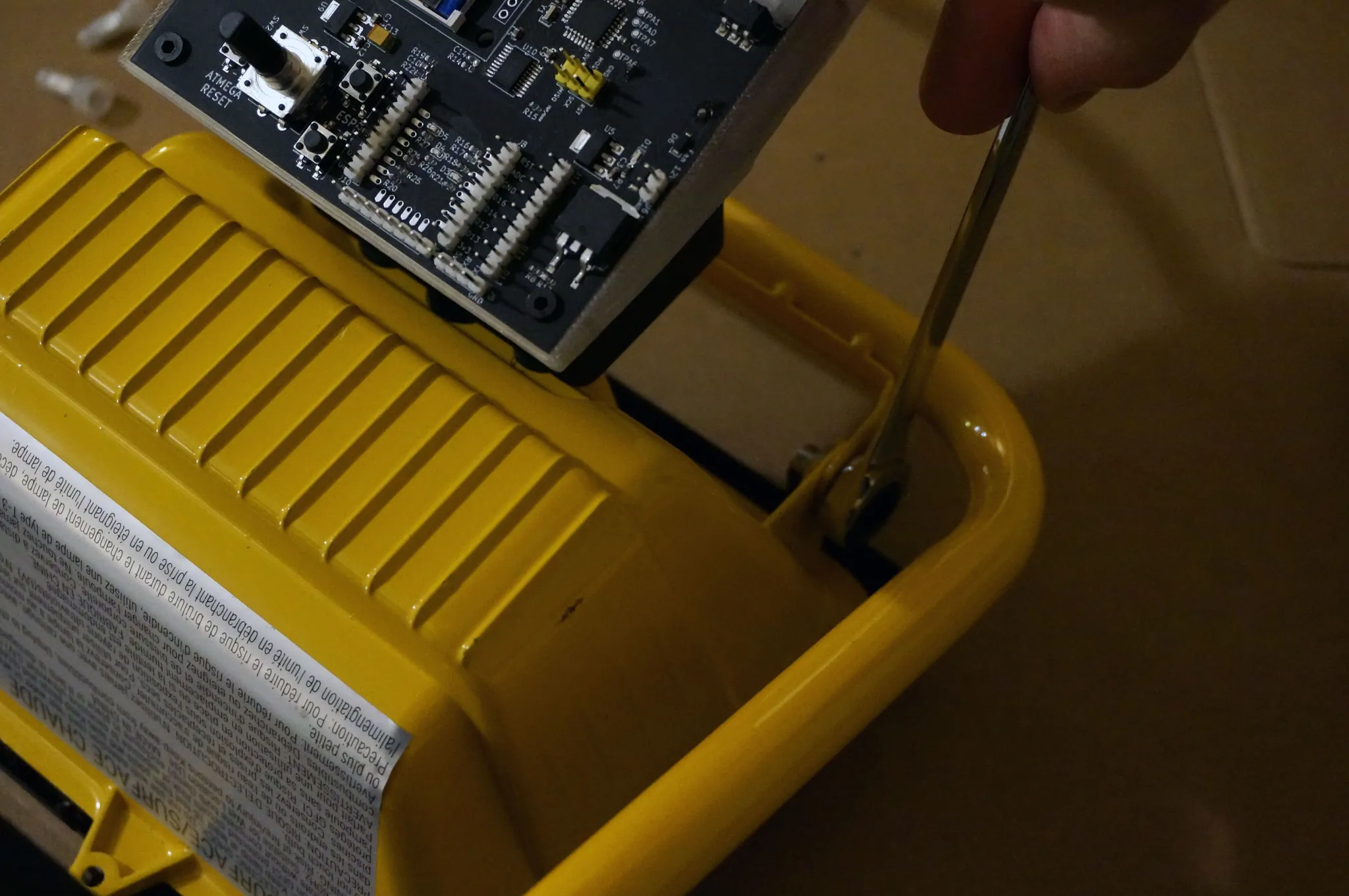
Note the angle of the handle in this photo.
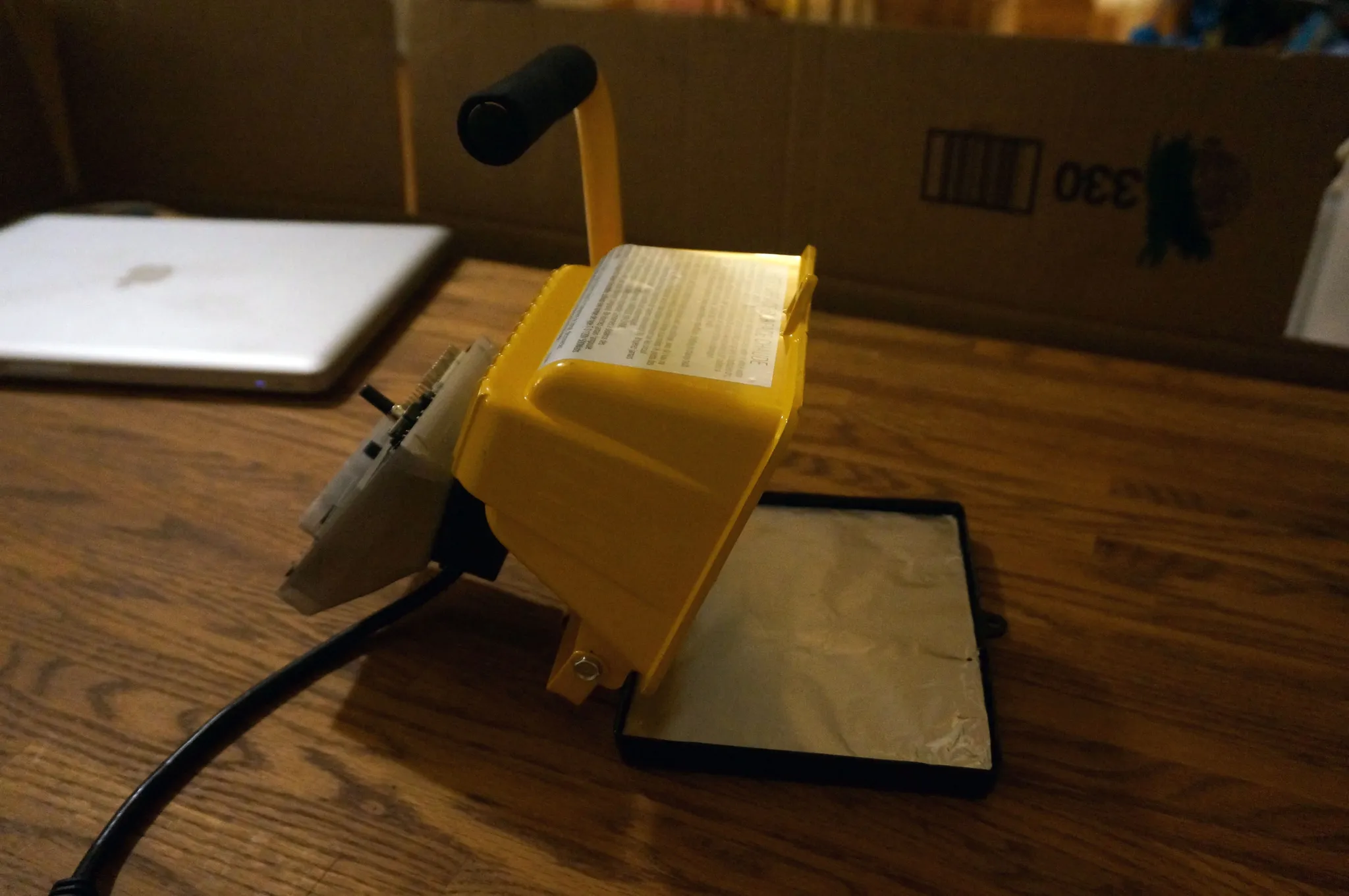
Install the aluminum-covered glass plate.
Removing the gasket will make it easier to open and close the lamp.
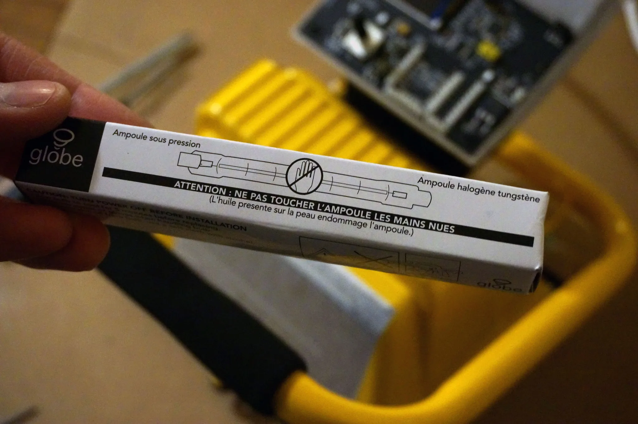
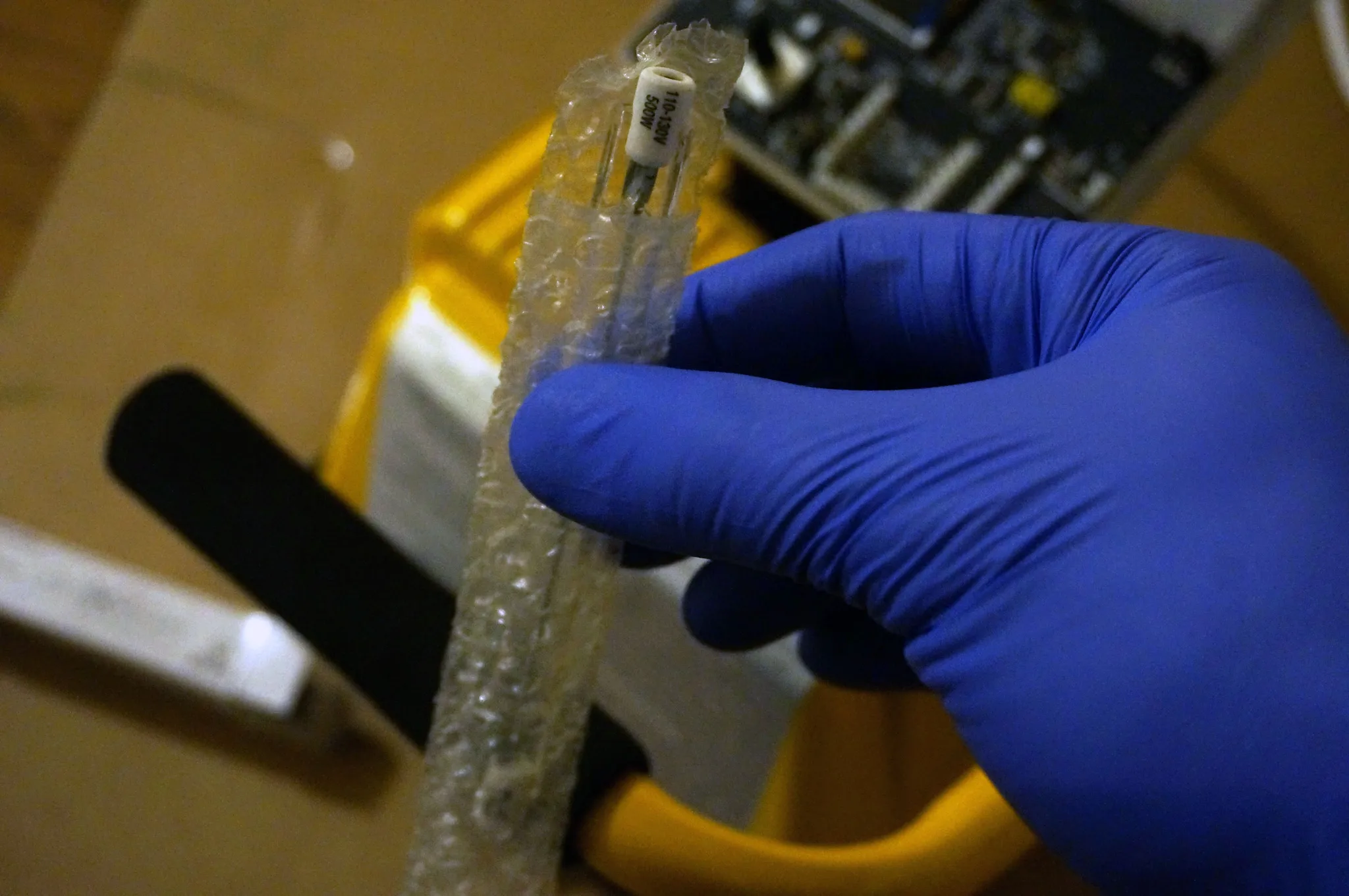
Install the included bulb, but be sure not to touch it with your bare hands! You should also be careful to avoid direct contact between the bulb and any liquid, now or in the future. I’ve never seen it happen, but I understand moisture on the bulb can cause catastrophic failure. If anyone knows of a quartz or infrared element that could be put in this fixture, I think that might be a better long-term option.
That’s it, we’re ready to load the firmware!
First-time Firmware Installation
You can skip this section if you’ve ordered an assembled board, as the firmware will already be flashed. You can use the WiFi firmware updating functionality to easily flash new firmware without connecting the board to your computer using the ESP8266.
Flashing the ATmega328p Bootloader
If you’ve purchased an ATmega328p without a bootloader, you can use the in-system programmer (ISP) headers to program the chip with a USBasp.
Be sure to set your USBasp to “slow mode” by putting a shunt on JP3.
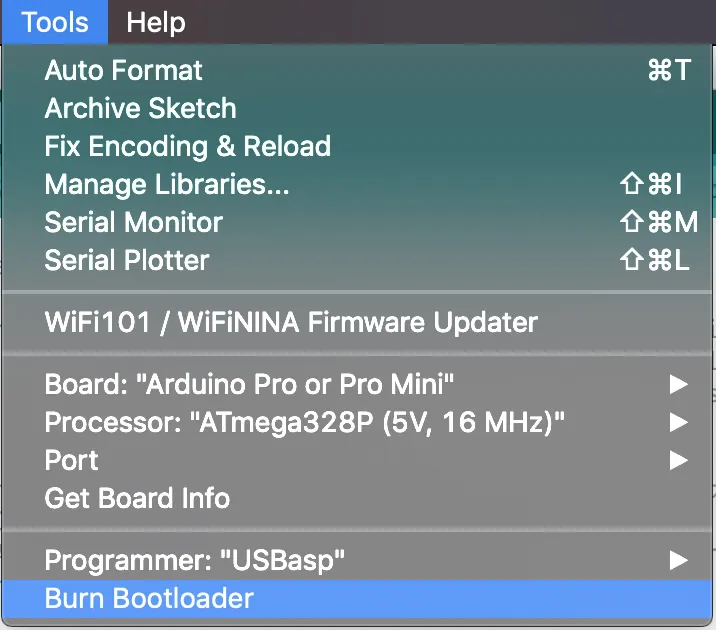
Download and open the Arduino Software package and open the Tools menu. Choose your Board: Arduino Pro or Pro Mini, Processor: ATmega328p (5V, 16MHz), then click Burn Bootloader.
Flashing the PowerCore esp-link firmware
An ESP8266 installed in a pre-assembled PowerCore will already have the firmware installed. If this is not the case for you, simply check out the code (to be released publicly with the Indiegogo campaign, email me if you need it before then) and open the esp-link project.
Set up your path by adding the top-level bin directory, as described in the project’s readme, and run:
esp make
pipenv install
pipenv run flash
While it says Connecting........____, press the ESP FLASH and RESET buttons, then release RESET, then FLASH.
WiFi Firmware Updating
The first time you use your PowerCore / FluxLamp, you’ll need to connect it to your WiFi.
Power up the PowerCore and connect to the ESP8266 WiFi network. The name will be FairyLink... or ESP....
Connect to the web interface via the default IP: http://192.168.4.1
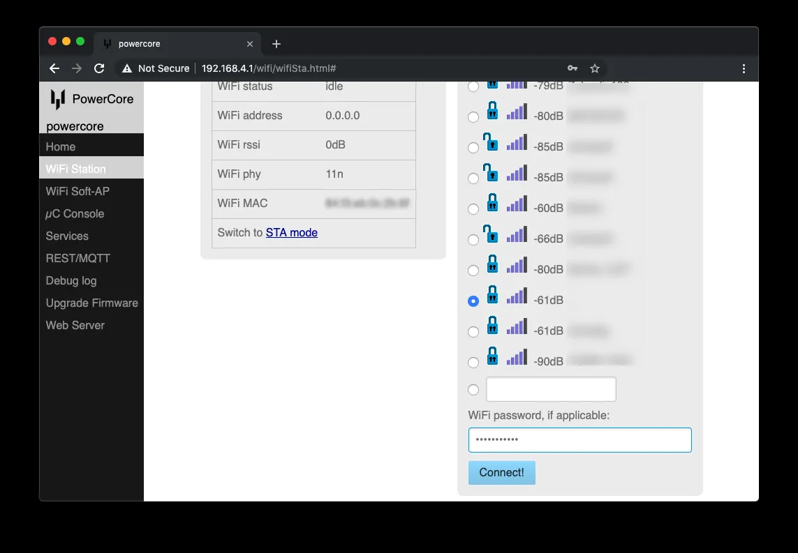
Under WiFi Station, click Switch to STA+AP mode, pick your WiFi network on the right, and click Connect!.
At the top, it will say your new IP.
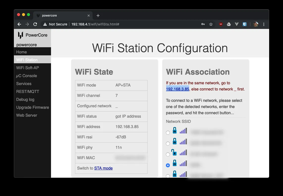
Go to the new IP and connect back to your normal WiFi network.
Under Pin Assignments, pick esp-12 swap, then switch Conn LED to GPIO4 and Serial LED to GPIO5 and hit Change!.
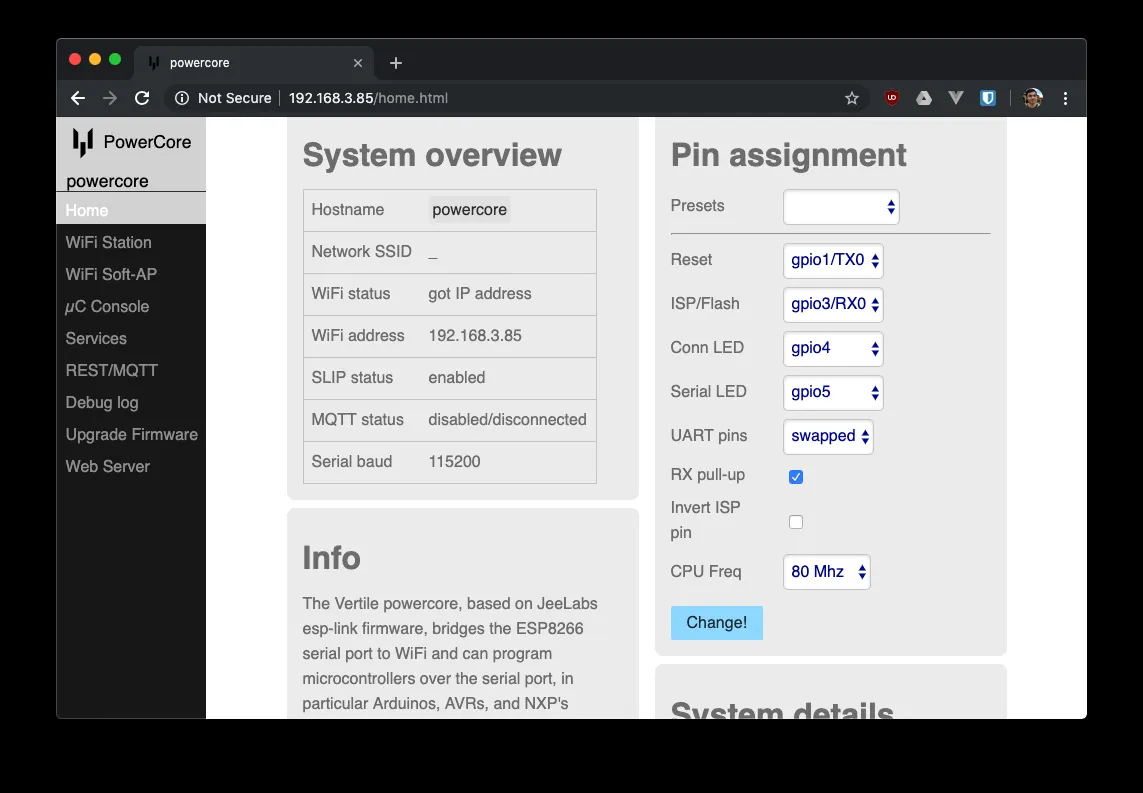
Make sure the jumpers on the UART port are installed and you can now upload an Arduino Sketch (see the FluxLamp app README.md).
Conveniently, from the fluxlamp app in the code, you can simply run (with the IP of your PowerCore):
IP=192.168.3.85 pio run -t uploadIf you would like to program another sketch, under “Info” you’ll see the flashing instructions to upload a sketch:
/home/arduino/hardware/tools/avrdude \
  -DV -patmega328p \
  -Pnet:192.168.3.85:23 \
  -carduino -b115200 \
  -U flash:w:my_sketch.hex:i\
  -C /home/arduino/hardware/tools/avrdude.conf
Acknowledgements
This project is inspired by work from a long line of folks. These people include David Kirbis, Karl Pitrich, and Ed Simmons; however, I am certain I have missed others that have contributed to open work in this area. The ESP8266 firmware is based on the esp-link by Jean-Claude Wippler. My immense thanks go out to these individuals and all others that have done work along this same vein.