Drone Building 101 with the HobbyKing FPV Starter Setup
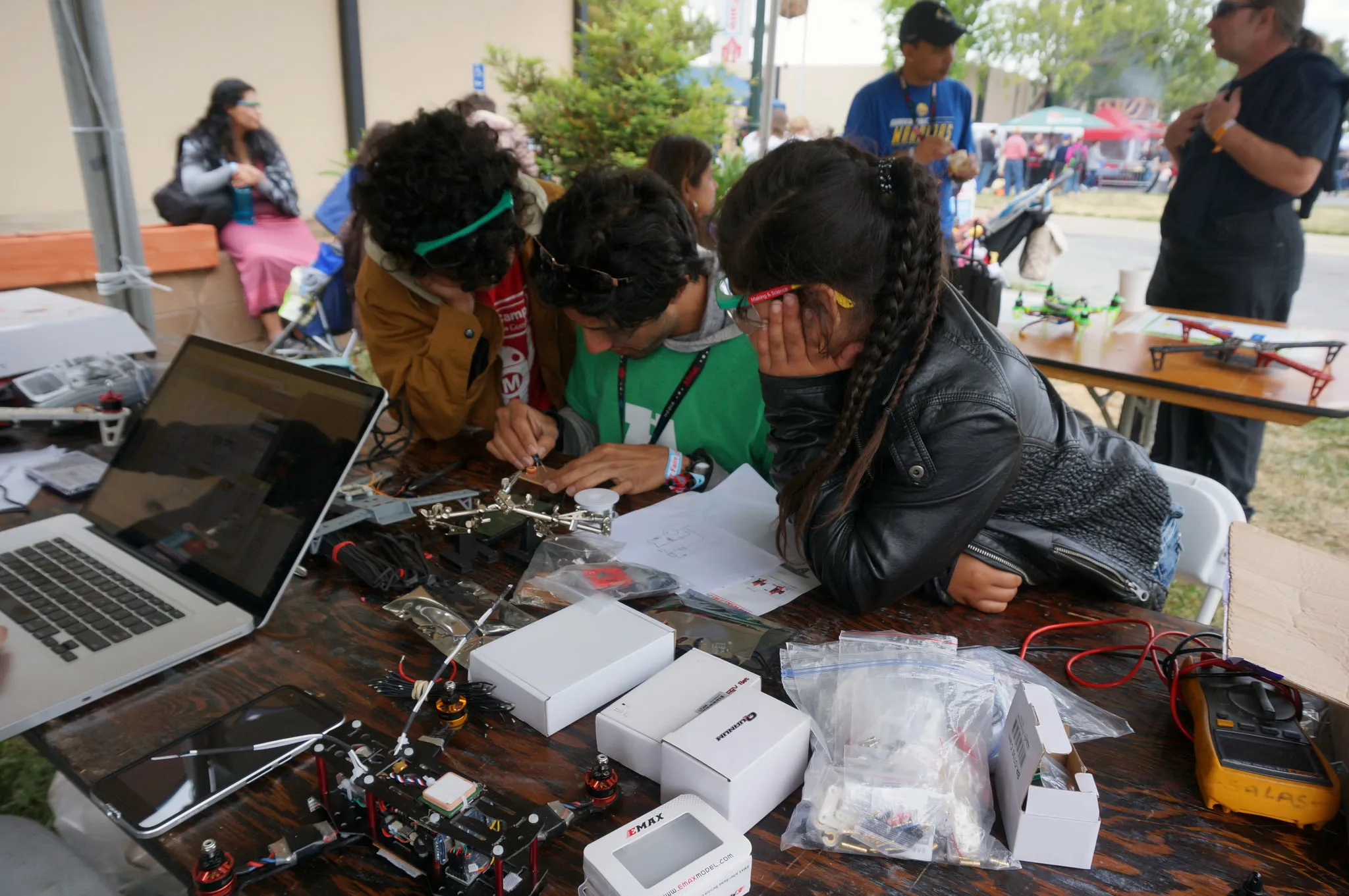
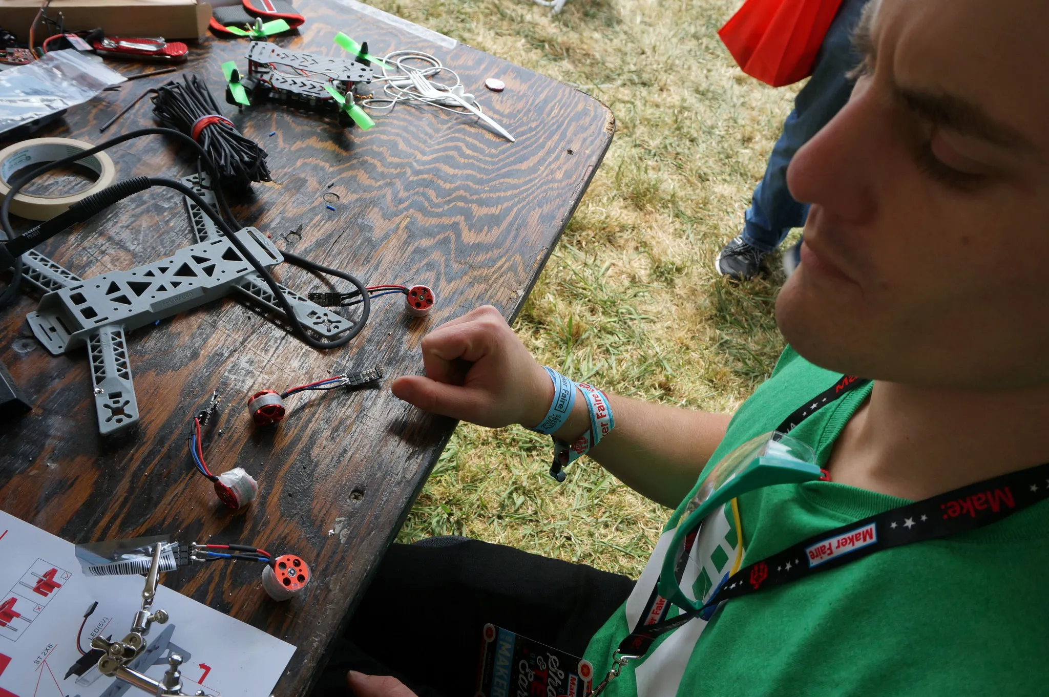
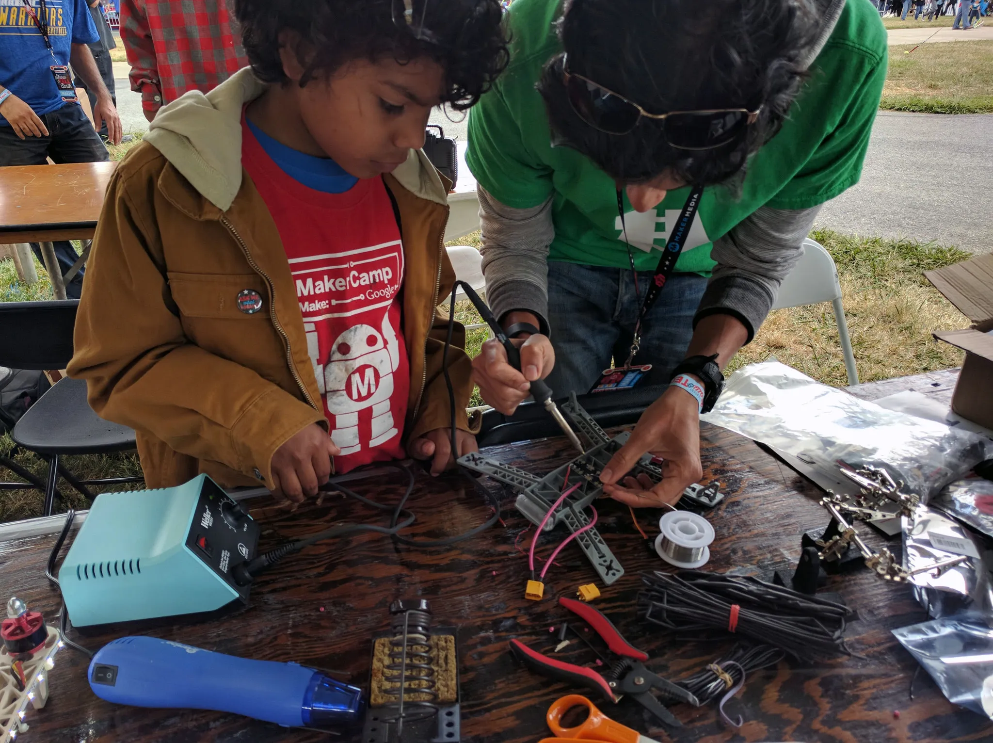
At Maker Faire Bay Area 2016, David, Jack, Huned and I built a drone with the help of some kids. This is the story of that drone.
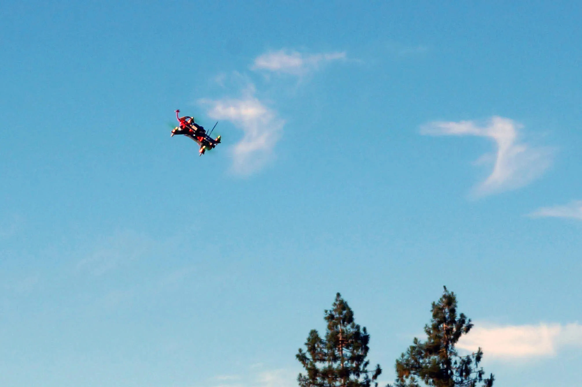
Let’s start with the results. Here is some video of the drone flying with the BetaFlight 3.0 firmware.
And chasing the drone with the
Parts
Here are all the parts we used:
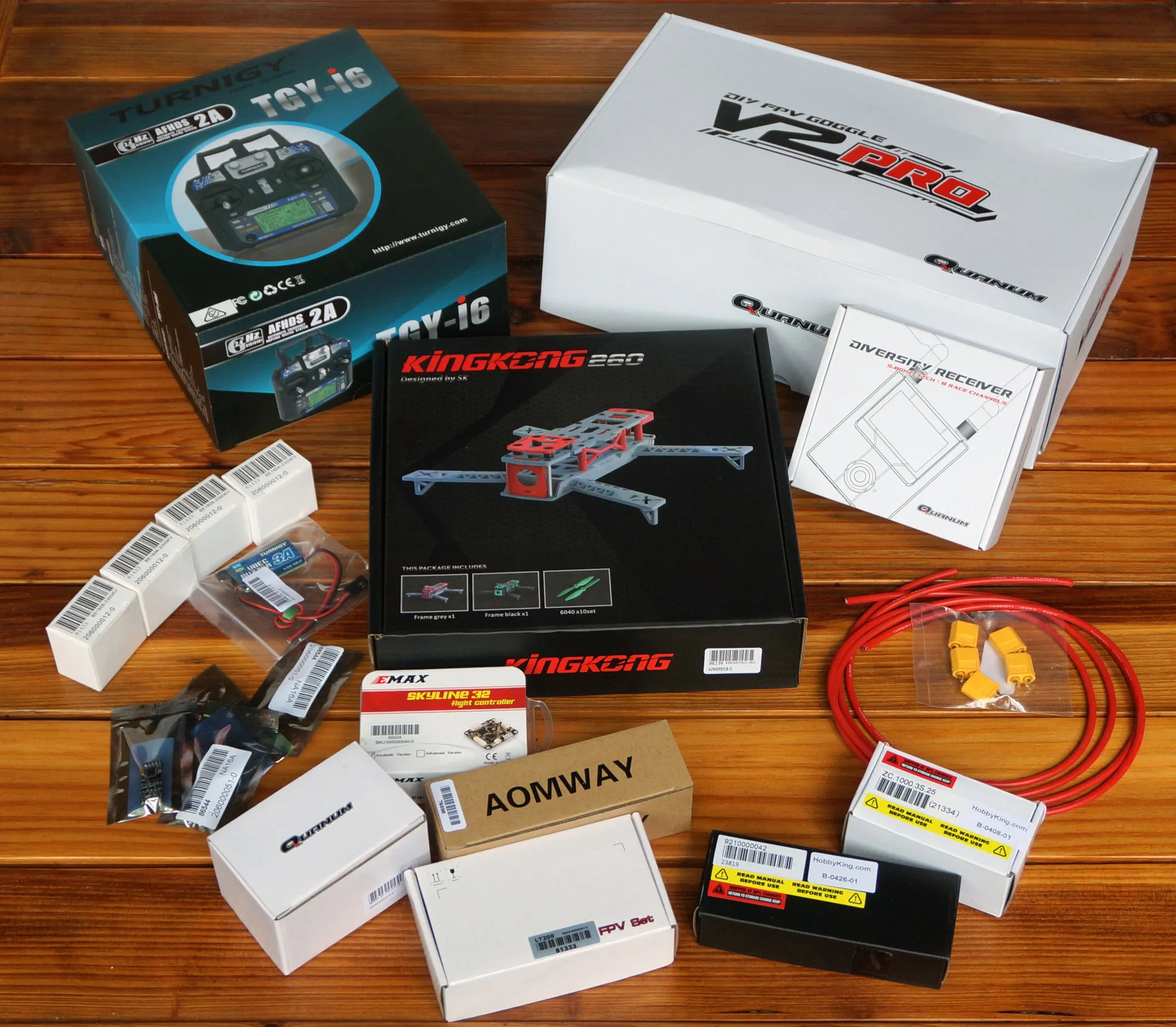
| Image | Description |
|---|---|
 | KingKong 260 FPV Frame Set (Pair) w/ props, $17.69 |
 | 4x DYS BLHeli 16A Mini ESCs 2-4s, $4.99 |
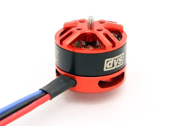 | 4x DYS BE1806 2300kv Motors, $8.95 |
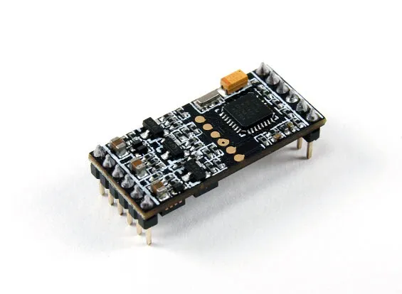
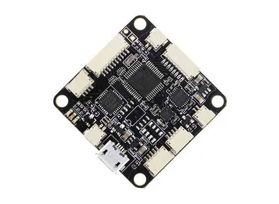 | Skyline Skyline32 Flight Controller, $14.99 |
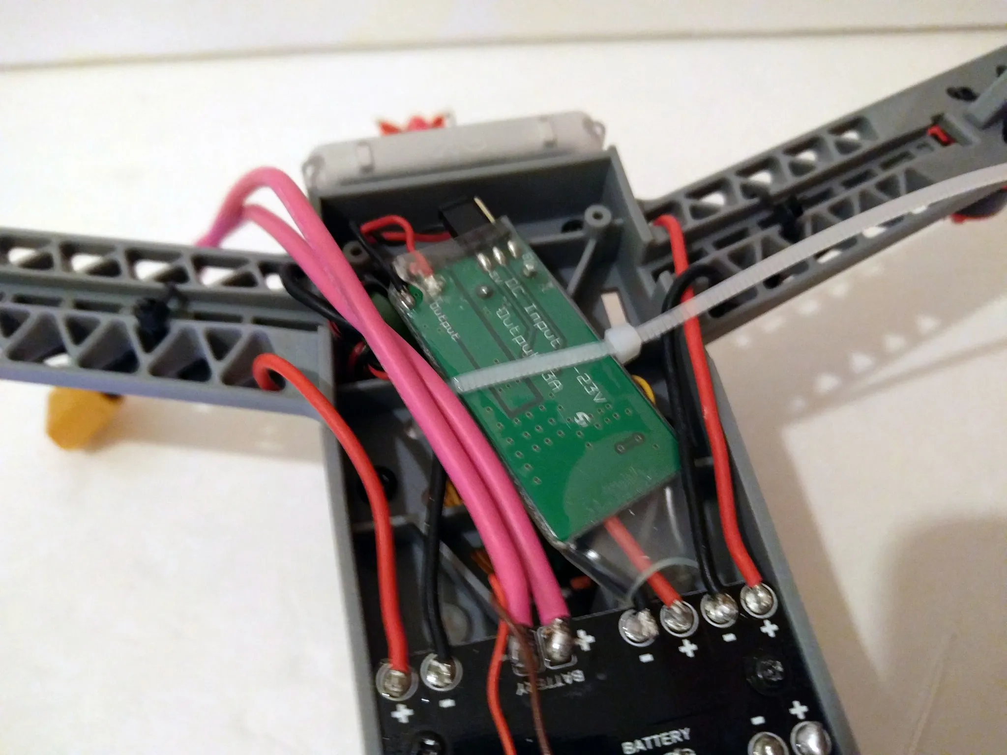
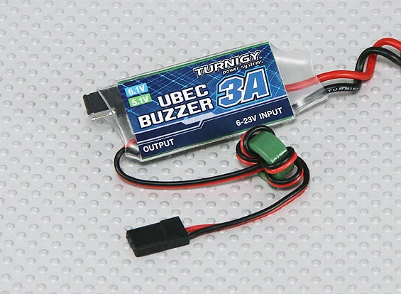 | 3A UBEC with Low Voltage Buzzer, $2.99 |
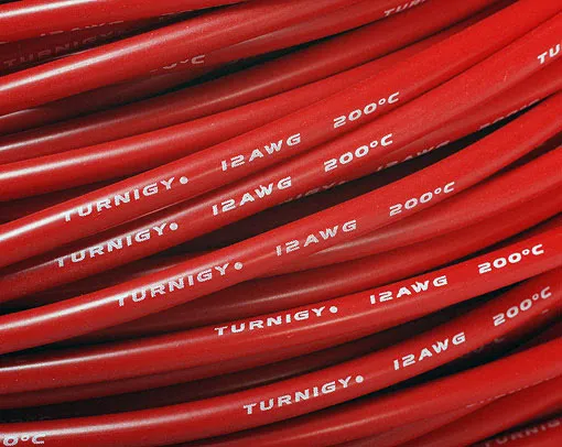 | 12ga Silicone Wire, $2.52 |
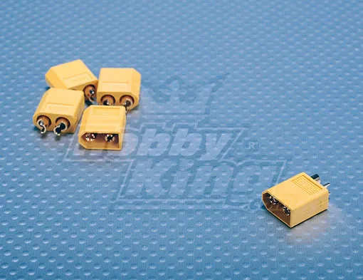 | XT-60 Connector, $1.94 |
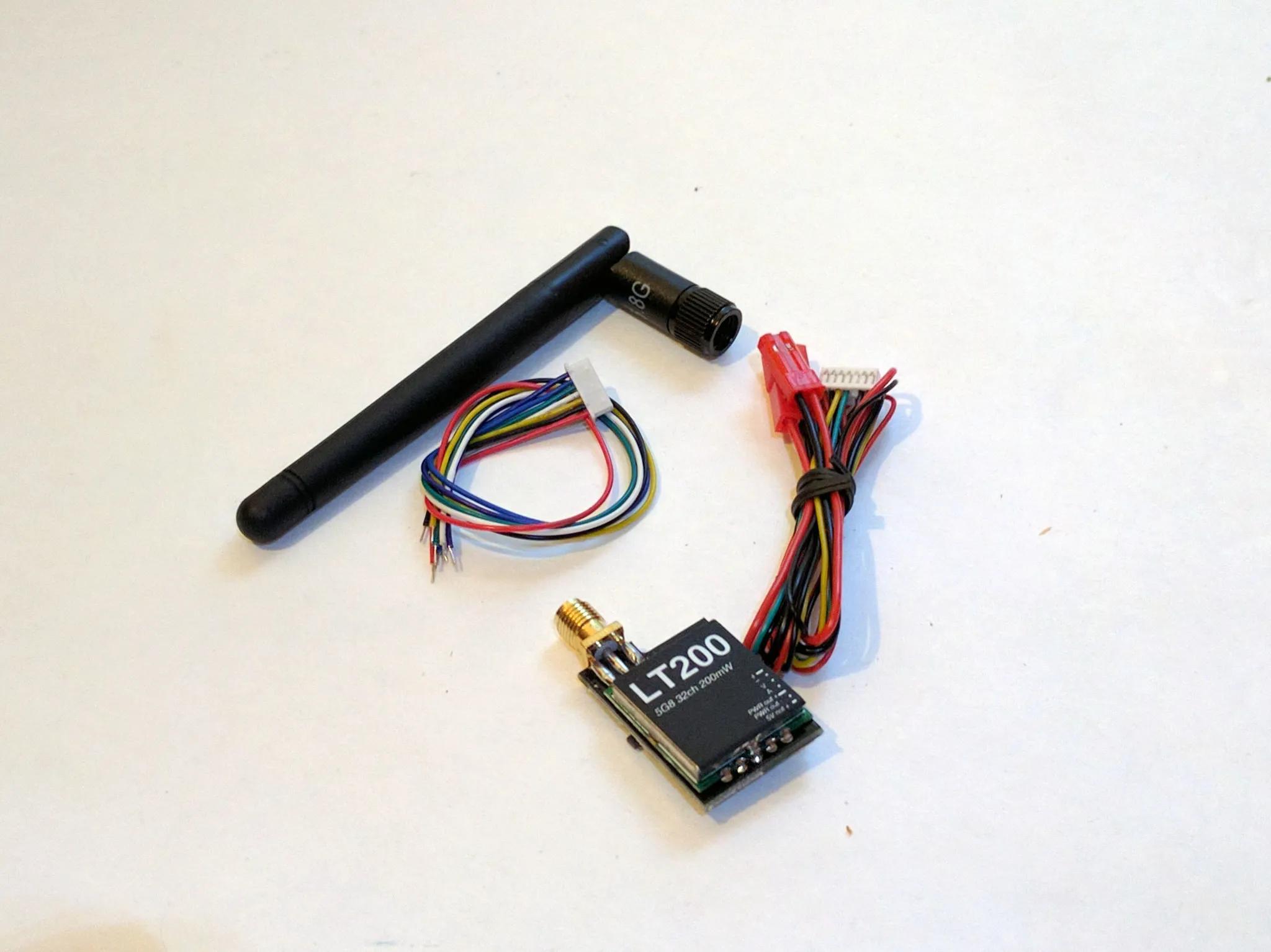
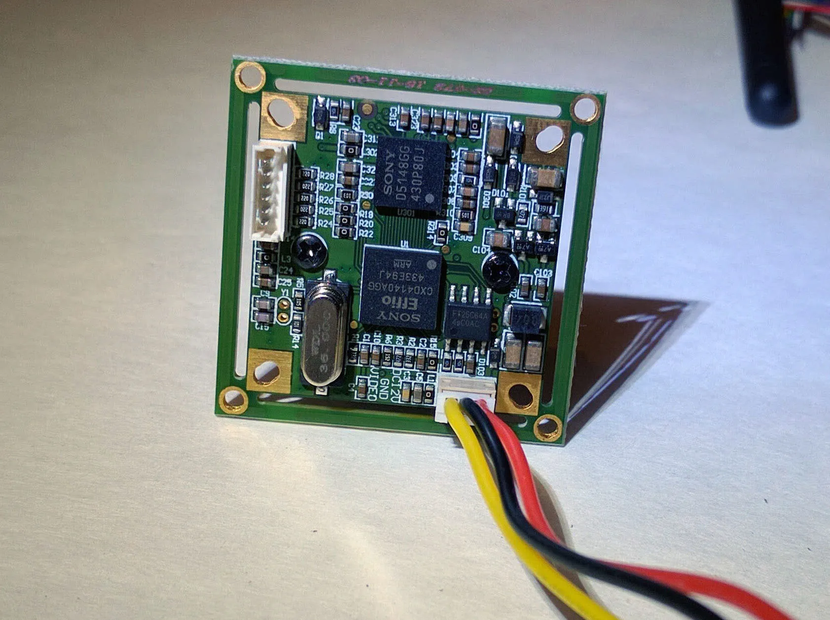
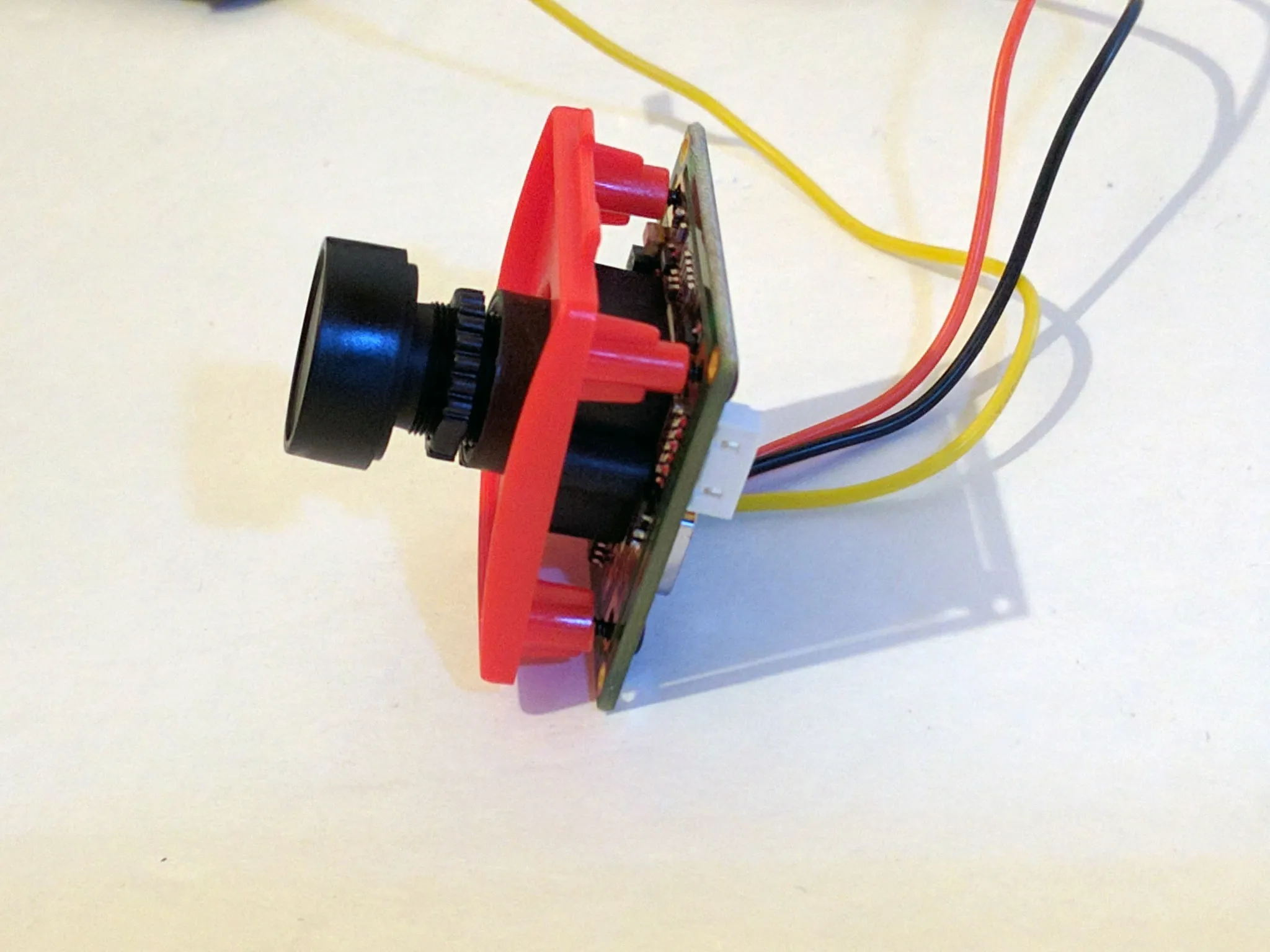
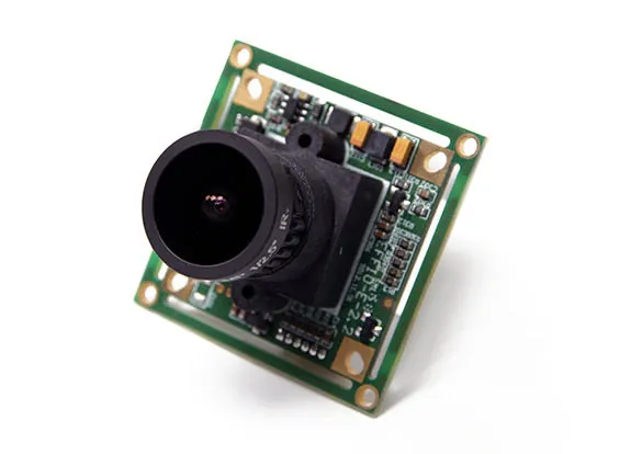 | 700TVL 1/3 2.1mm Sony CCD Camera, $34.49 |
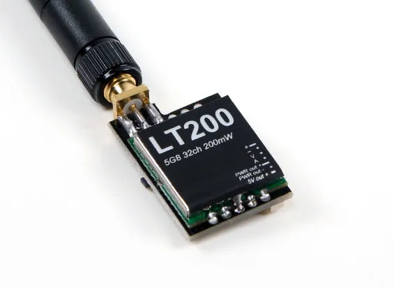 | LT200 5.8GHz 200mw 32 Channel FPV Transmitter, $16.48 |
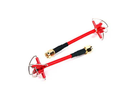 | Aomway 5.8GHz 4-Leaf Clover Antenna Set for TX/RX (RP-SMA) (RHCP), $7.40 |
Total: $153.55
Note, I ordered the ESCs listed above because they were the lightest weight and cheapest ESCs available. However, they are very small and very difficult to solder as well. If this is your first build, I highly recommend that you choose an easier ESC to work with. The Turnigy Multistar 20A V2 Slim BLHeli Multi-Rotor Brushless ESC 2-6S is an excellent value and should be much easier to work with.
| Image | Description |
|---|---|
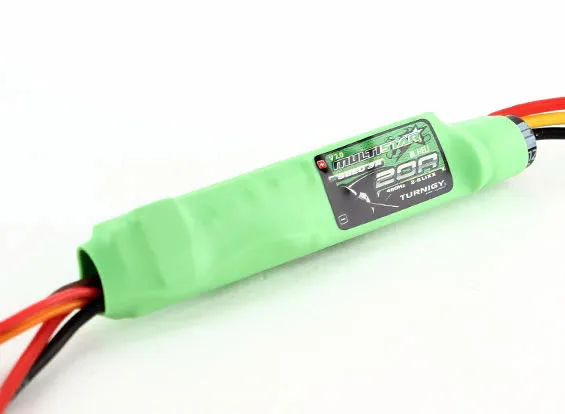 | 4x Turnigy Multistar 20A V2 Slim BLHeli Multi-Rotor Brushless ESC 2-6S, $4.99 |
Getting Started
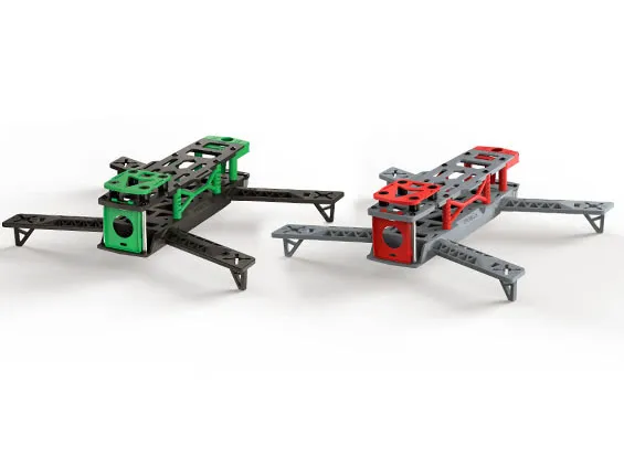
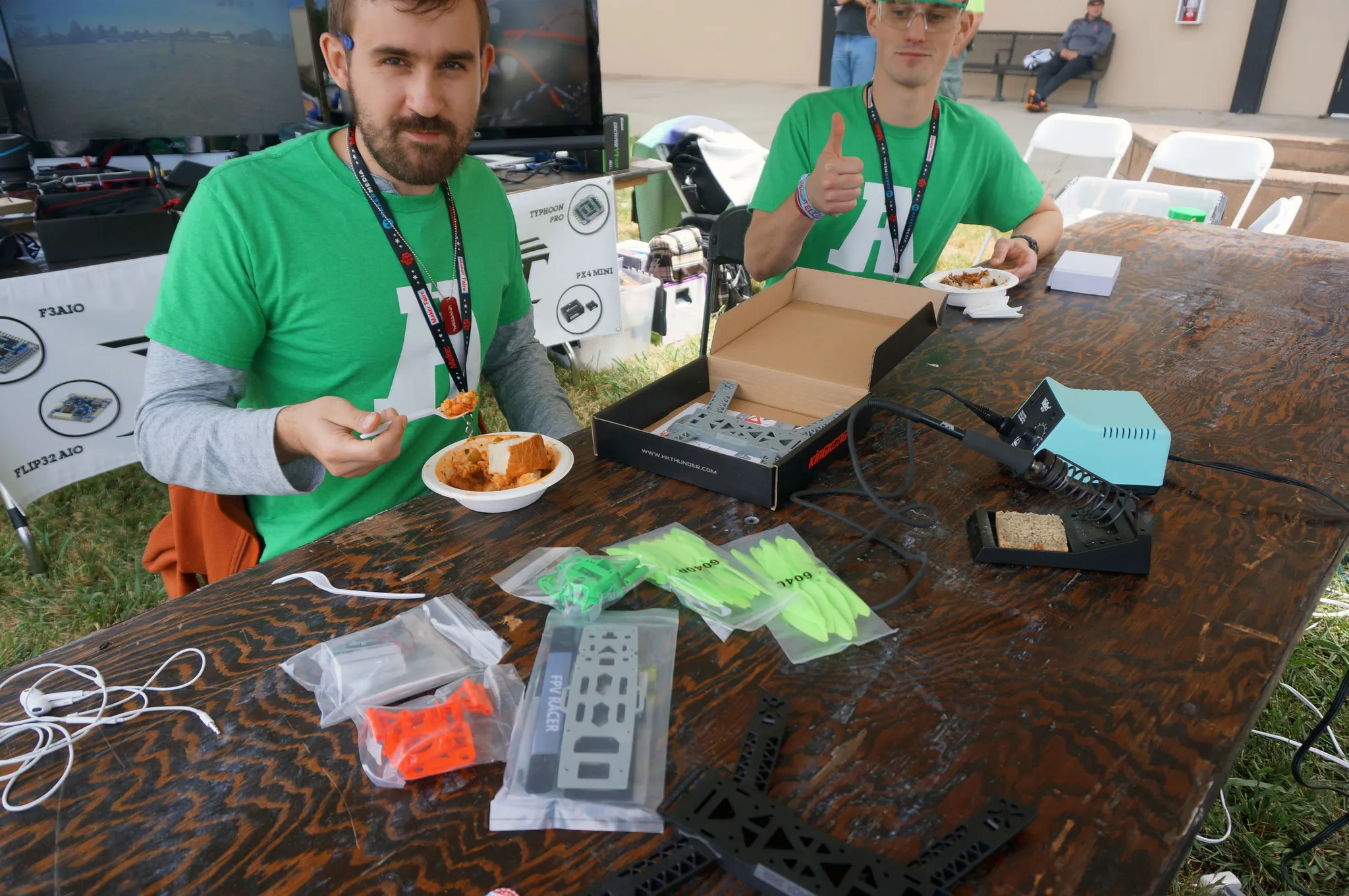
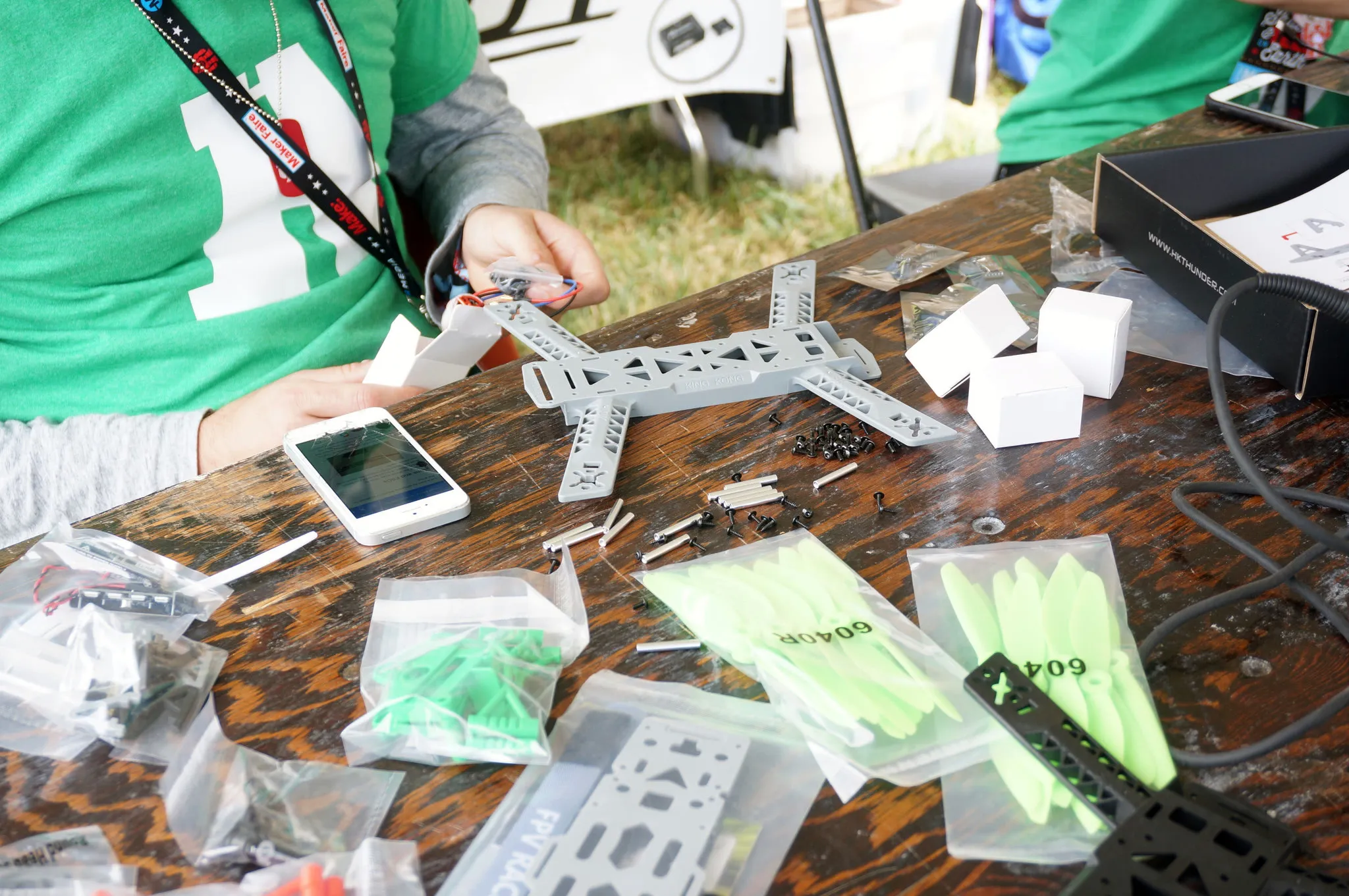
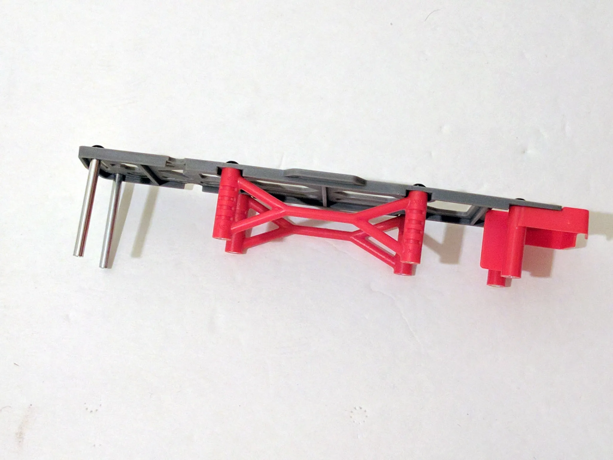
Start with the frame, and lunch, if you’re hungry. The frame kit is awesome, it comes with two whole frame sets, so if you break any parts, you’ll have plenty of backups.
You’ll be really tempted to get out all the little screws and stuff for the frame and start assembling it. Don’t do that yet though.
Power System
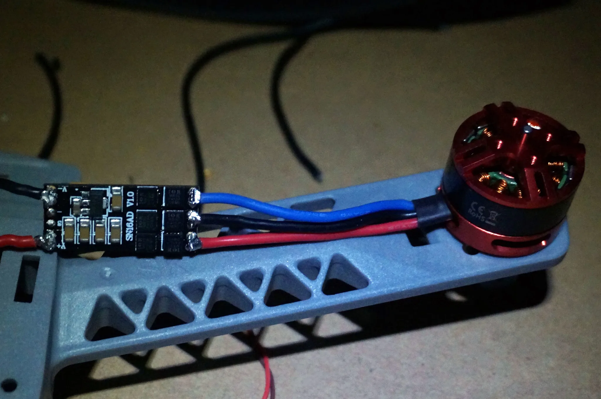
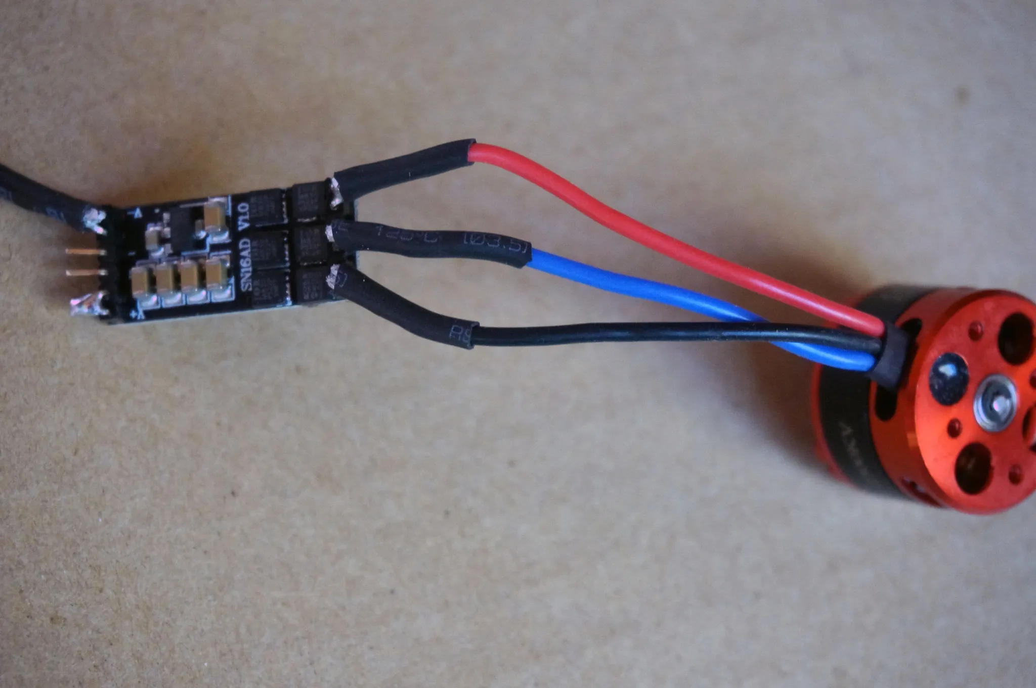
Instead, we’ll prep the motors and ESCs.
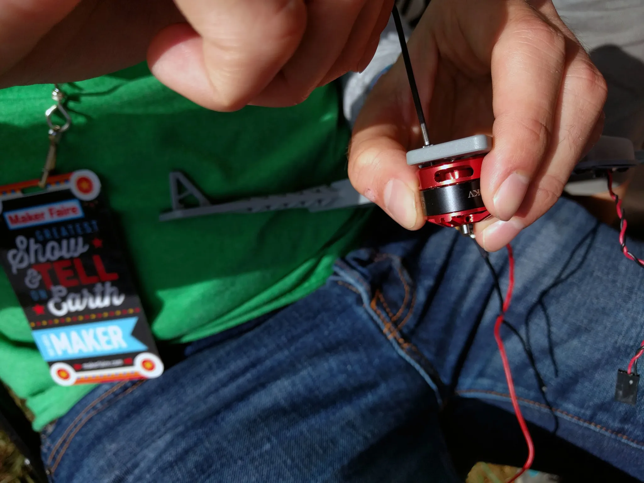
Cut the motor wires to length. We’ll be putting the ESCs on the arms, but if you want, there might be room to mount them under the body, in which case you would want slightly longer wires.
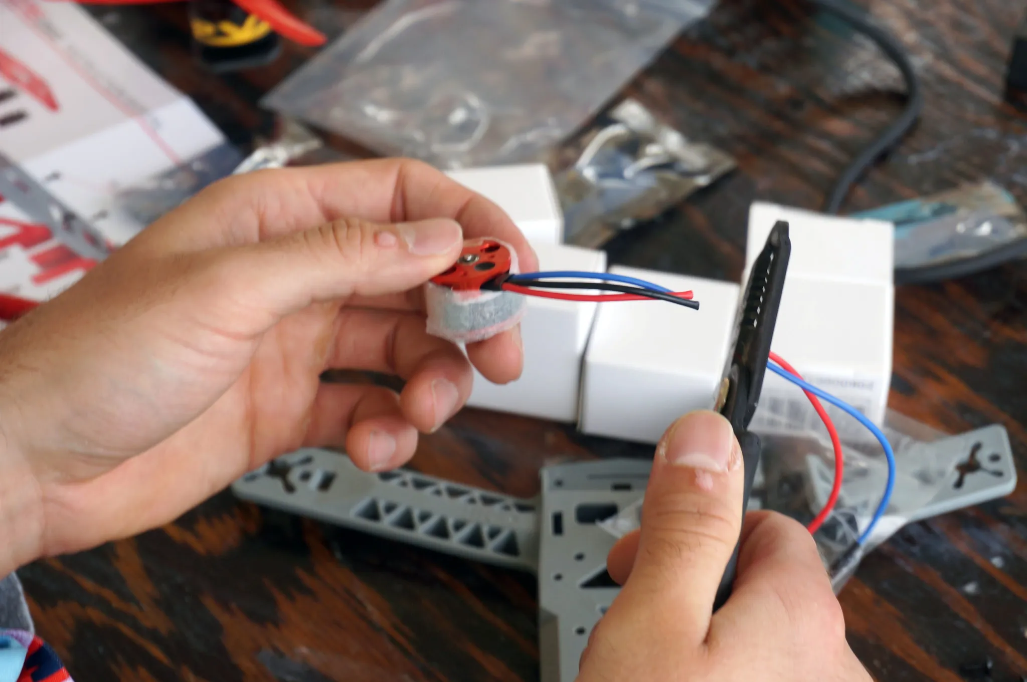
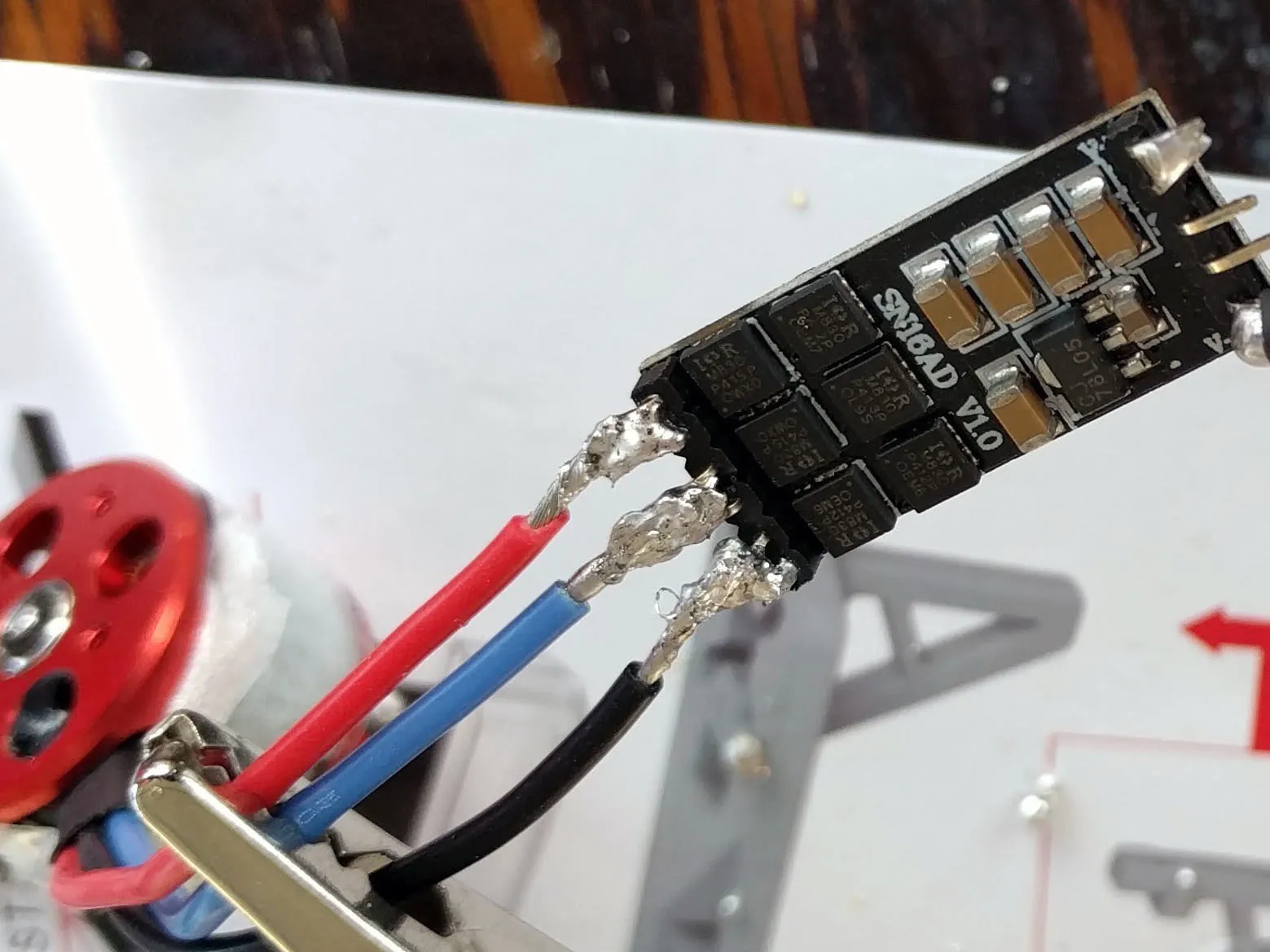
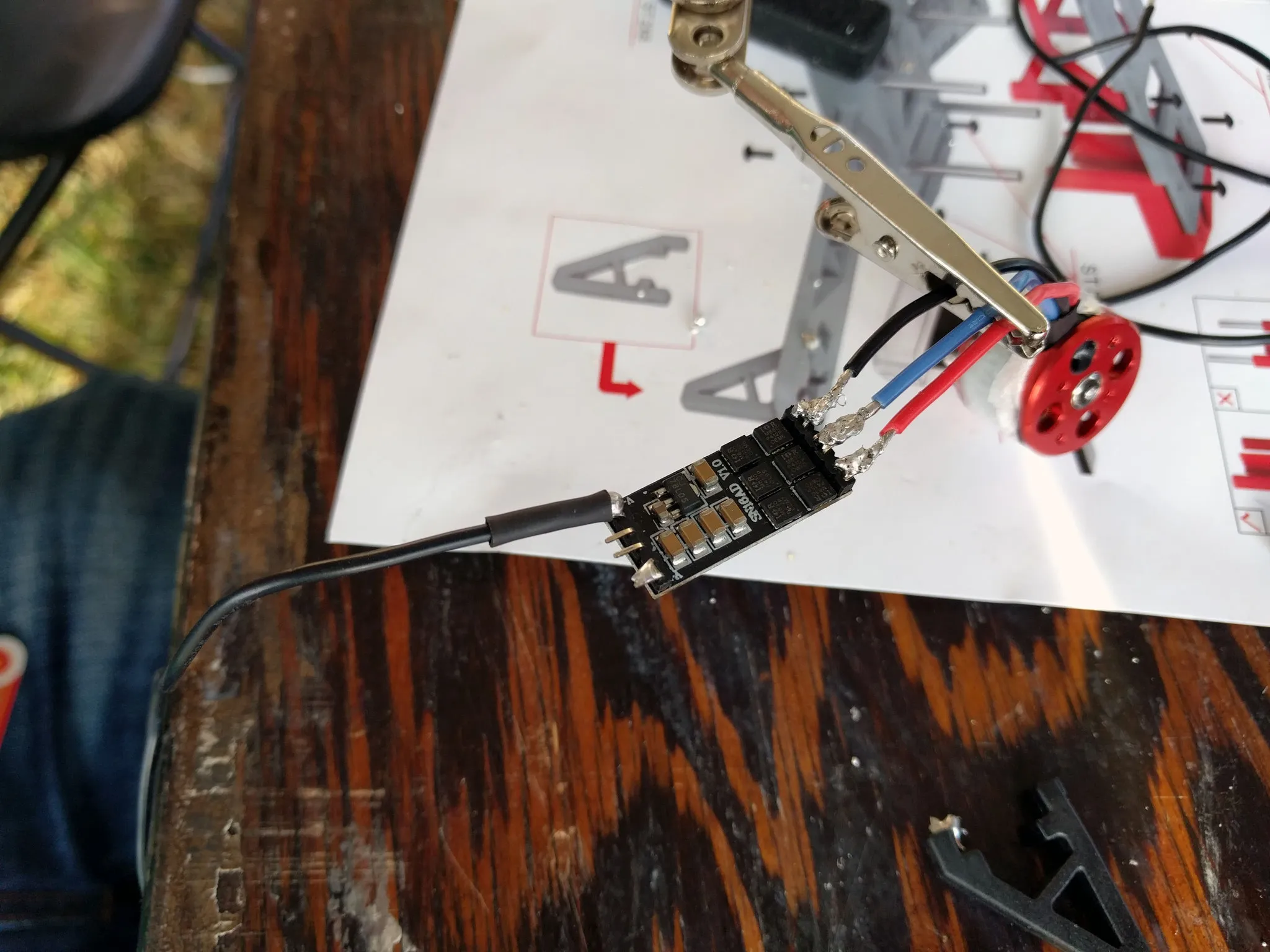
Prepare the ESCs by bending all the pins down at a 90 degree angle
Now strip the wires and tin them, it helps to have some helping hands. You’ll also want to bend the pins on the ESC down and together into pairs of two, so they’re easier to solder.
Be sure to slide some heat shrink onto the motor wires before soldering them on.
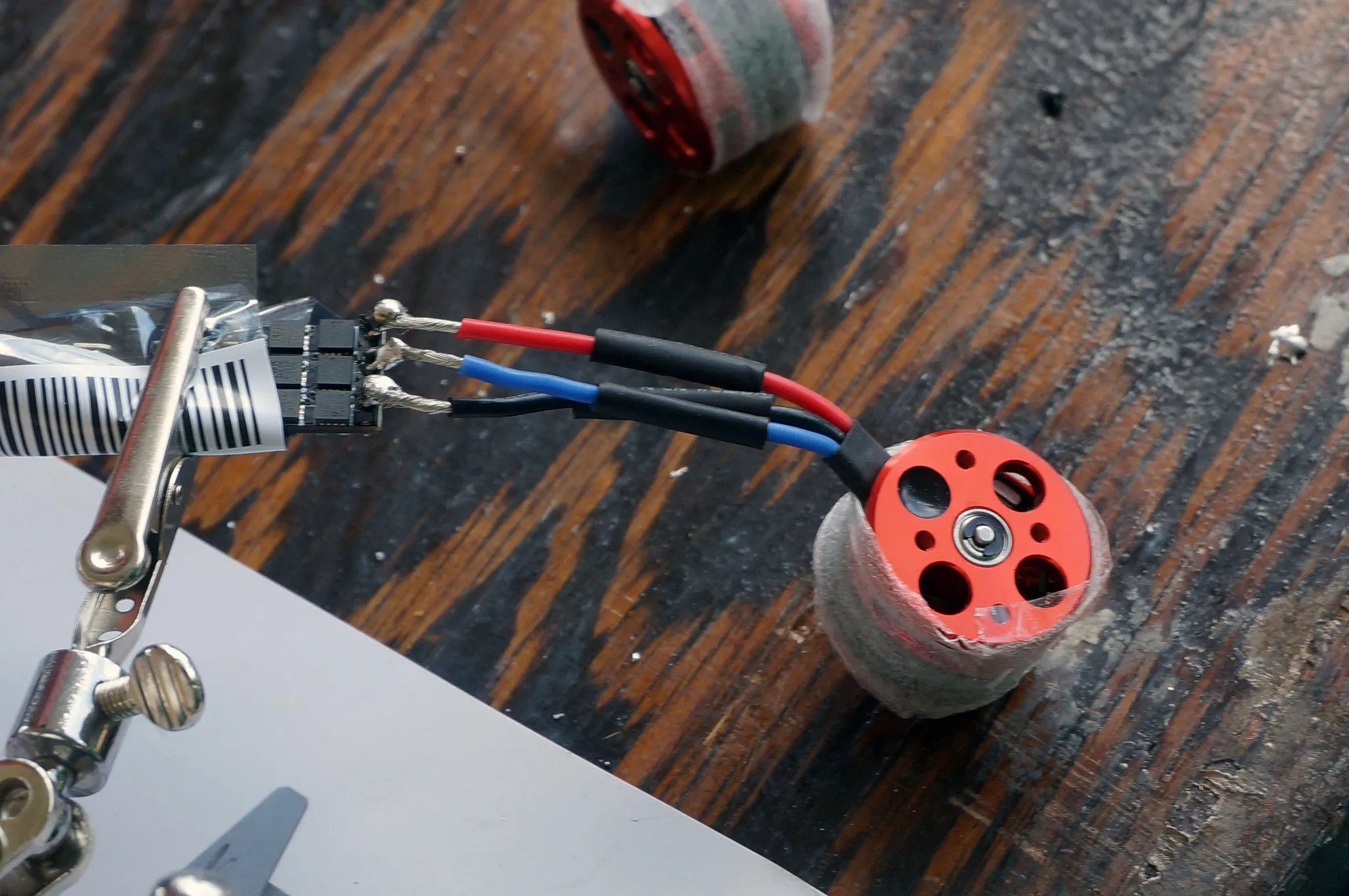
Notice we’re soldering the motor to the “bottom” side, if you orient the text upright.
Motor Order
The wiring order between the motors and ESCs determines which way the motors will spin. I’ll refer to the motors by their number as shown in this diagram:

Two motors should have the wires directly connected, not crossed. These motors will spin counter-clockwise and should be positioned at motors 2 and 3.
The other two motors should have two of the wires crossed, like so. They’ll be placed at position 1 and 4.
Complete all four motor / ESC sets. Frowning inquisitively when done is optional.
Next solder on the power and ground wires to the V+ and V- pins respectively, using the same technique of bending and soldering the pins together.
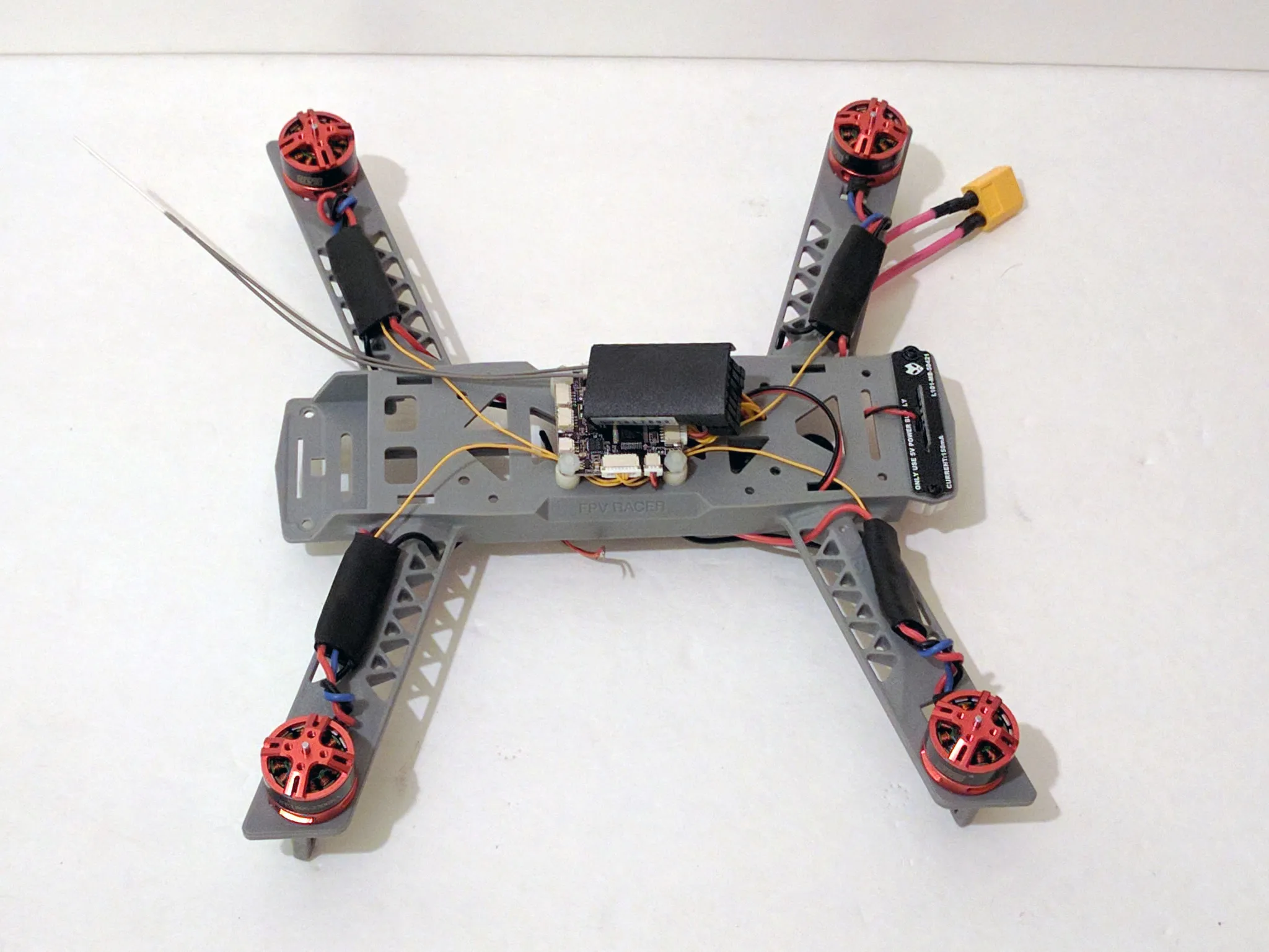
Repeat with all four ESCs and then screw the motors onto the frame, placing them in the proper position as noted in the motor order section above.
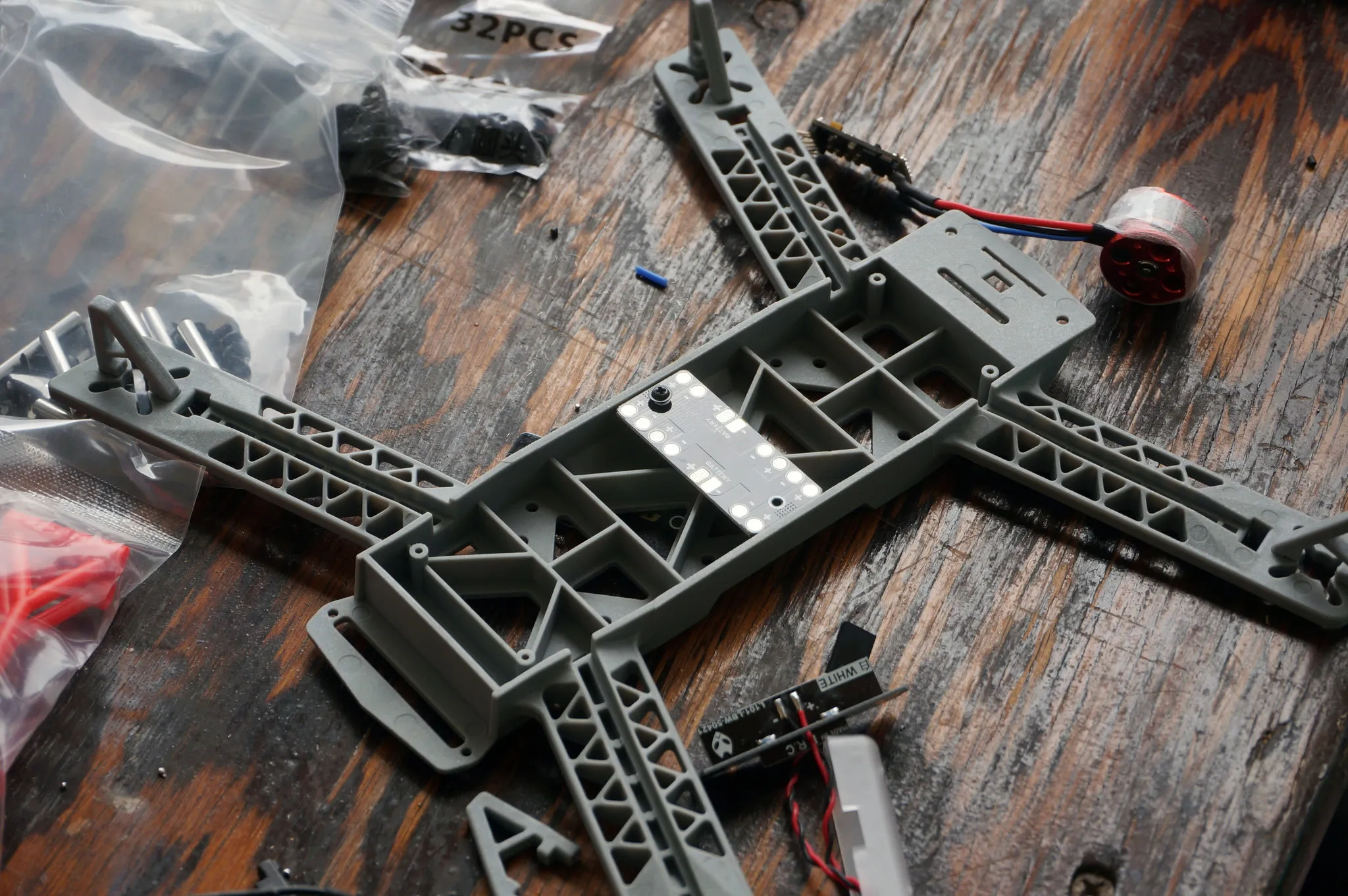
PDB
Now would be a good time to install the PDB on the bottom of the quadcopter.
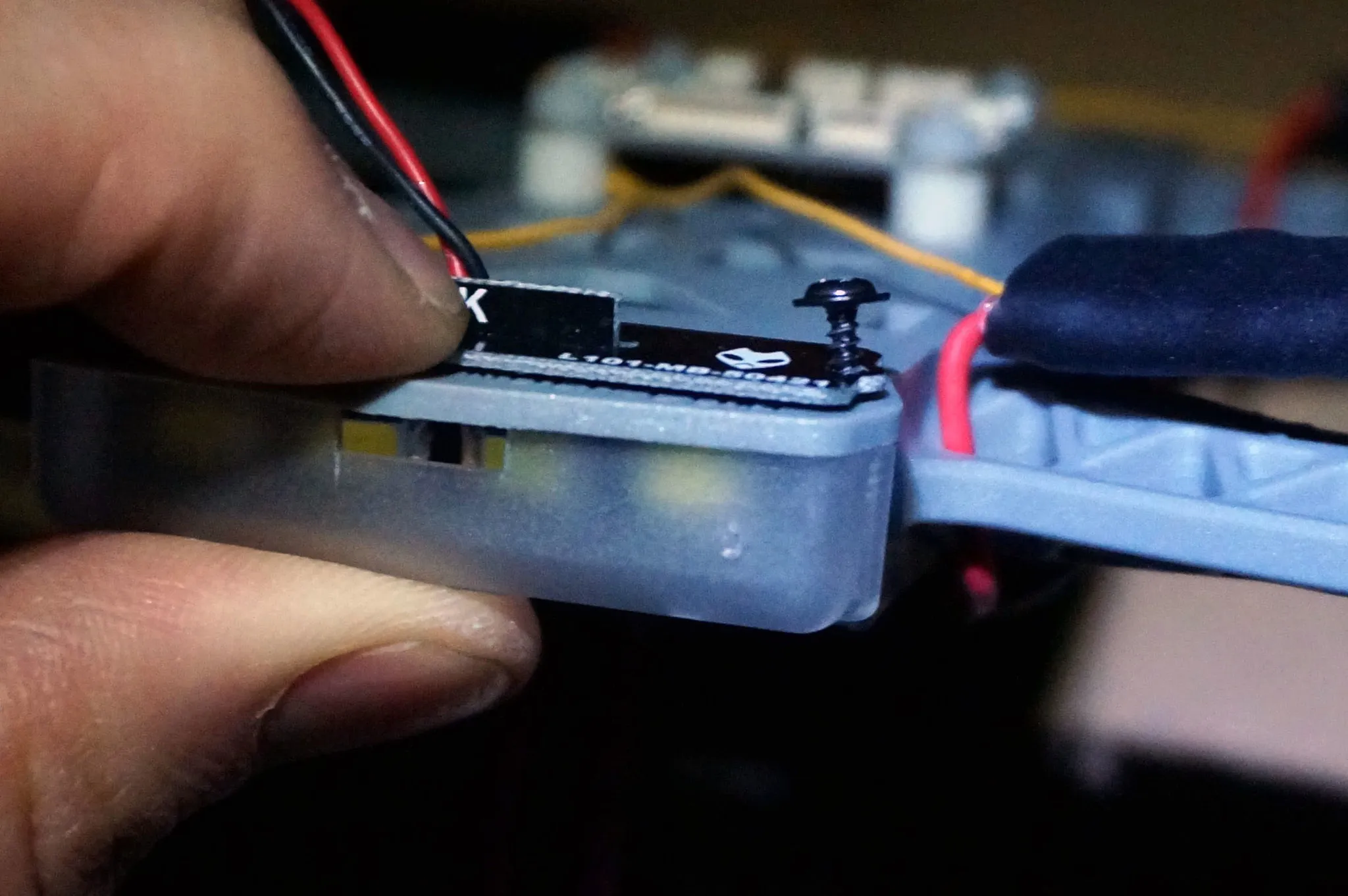
Install the LEDs onto the back of quad copter, make sure the LEDs point out towards the back.
Whoops, we installed them the wrong way the firs time. This is how they should be installed.
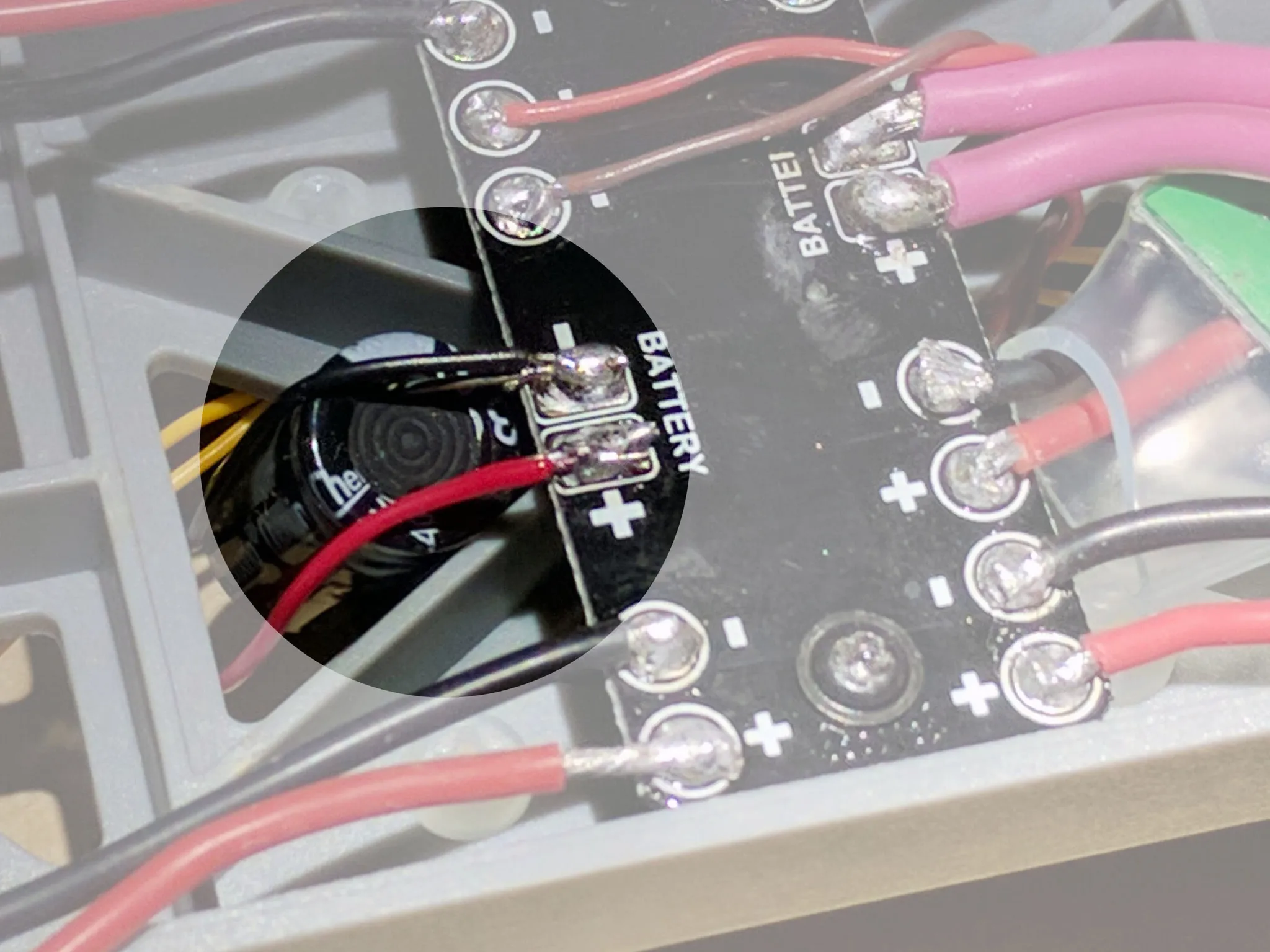
Also, if you want to use heat shrink to protect the ESCs, slide some over before soldering the power wires to the PDB. I came back and did this later.
Now route the power wires from the ESC down through the frame and solder them to the PDB.
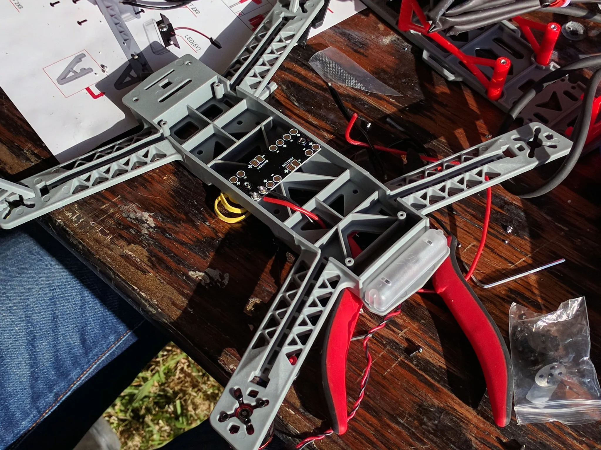
Solder the wires onto the XT-60 plug.
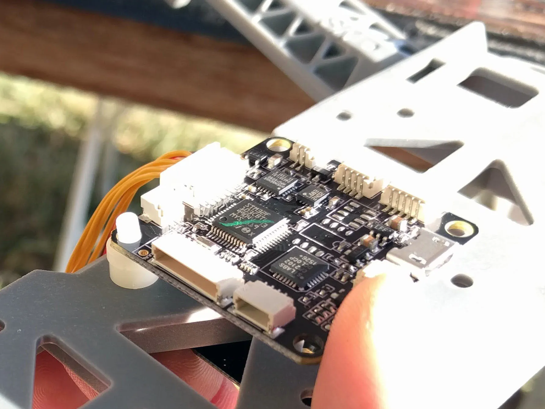
Flight controller
Ok, time for the flight controller.
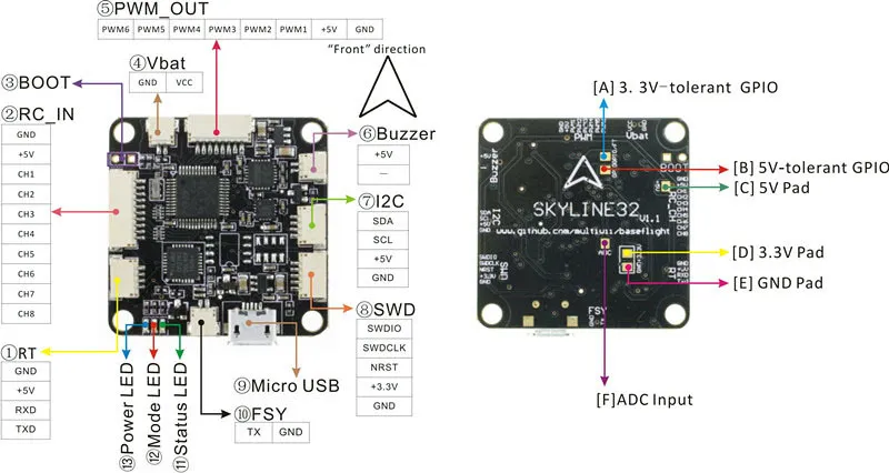
Here is the pinout diagram
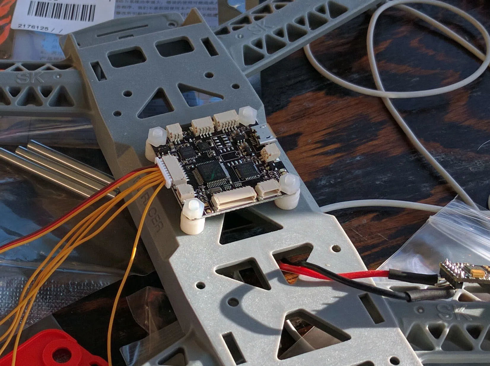
Install the standoffs.
Here’s what it looks like when it’s done.
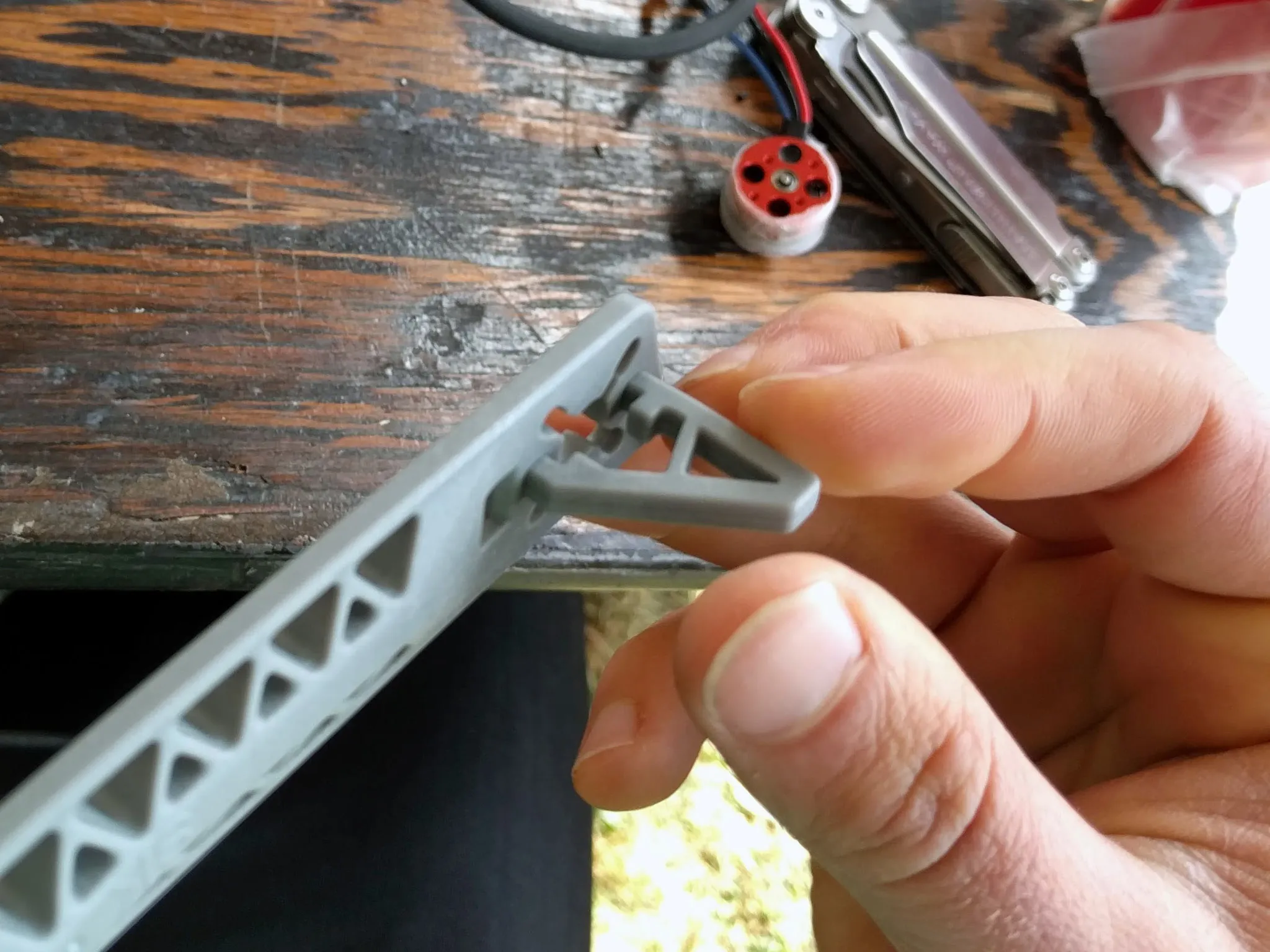
Now is a good time to install the landing gear.
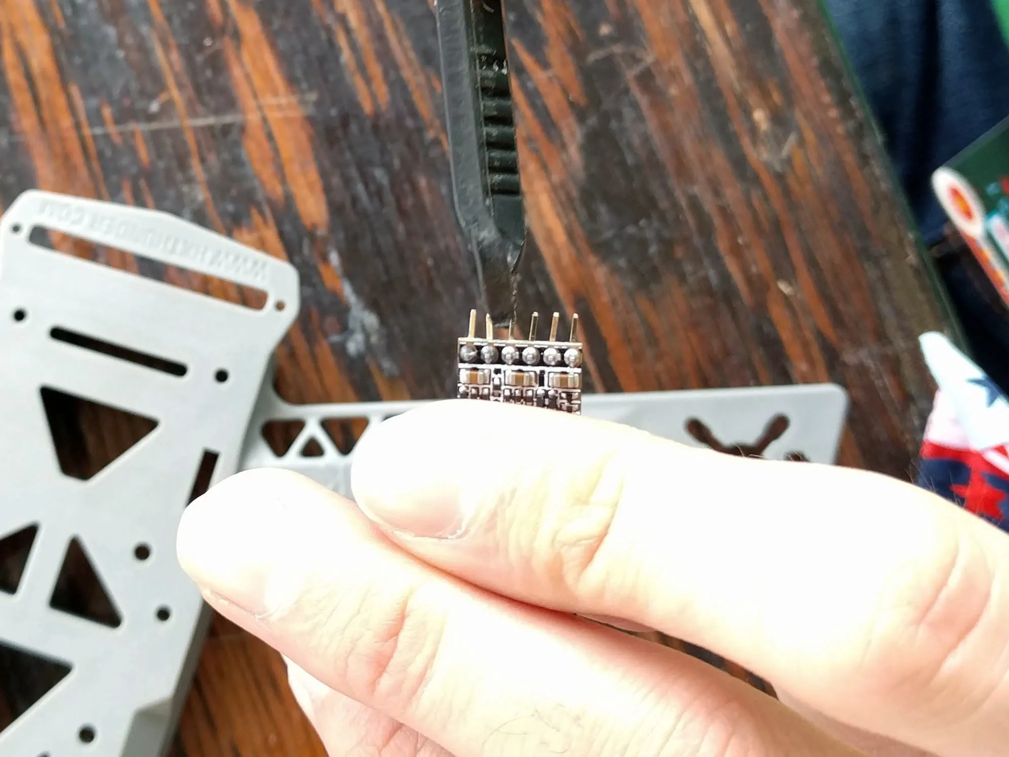
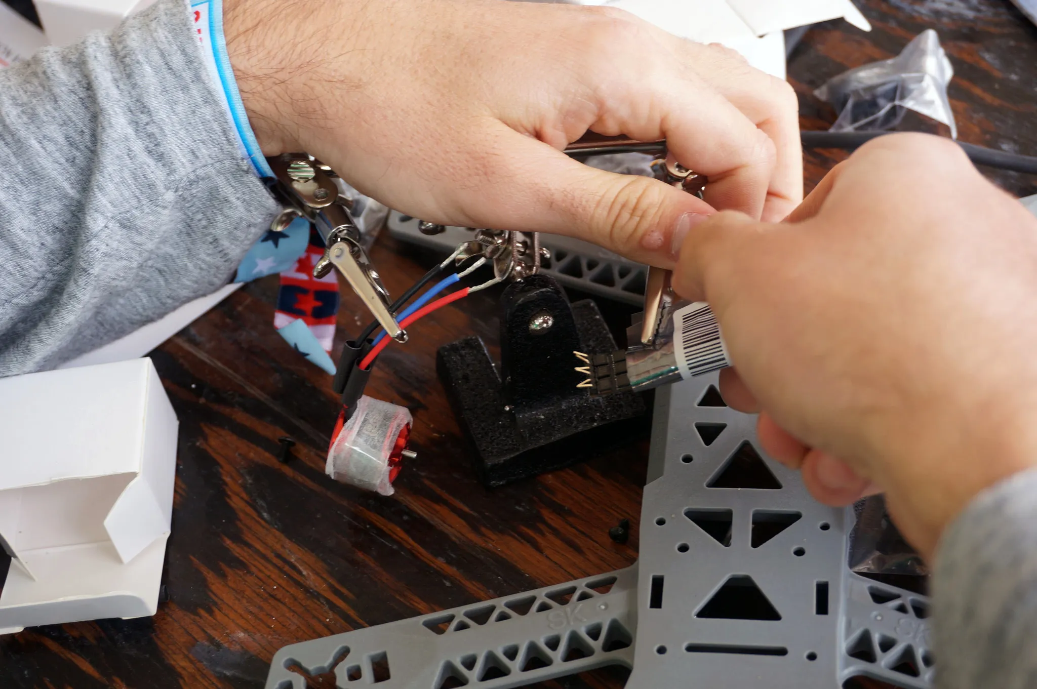
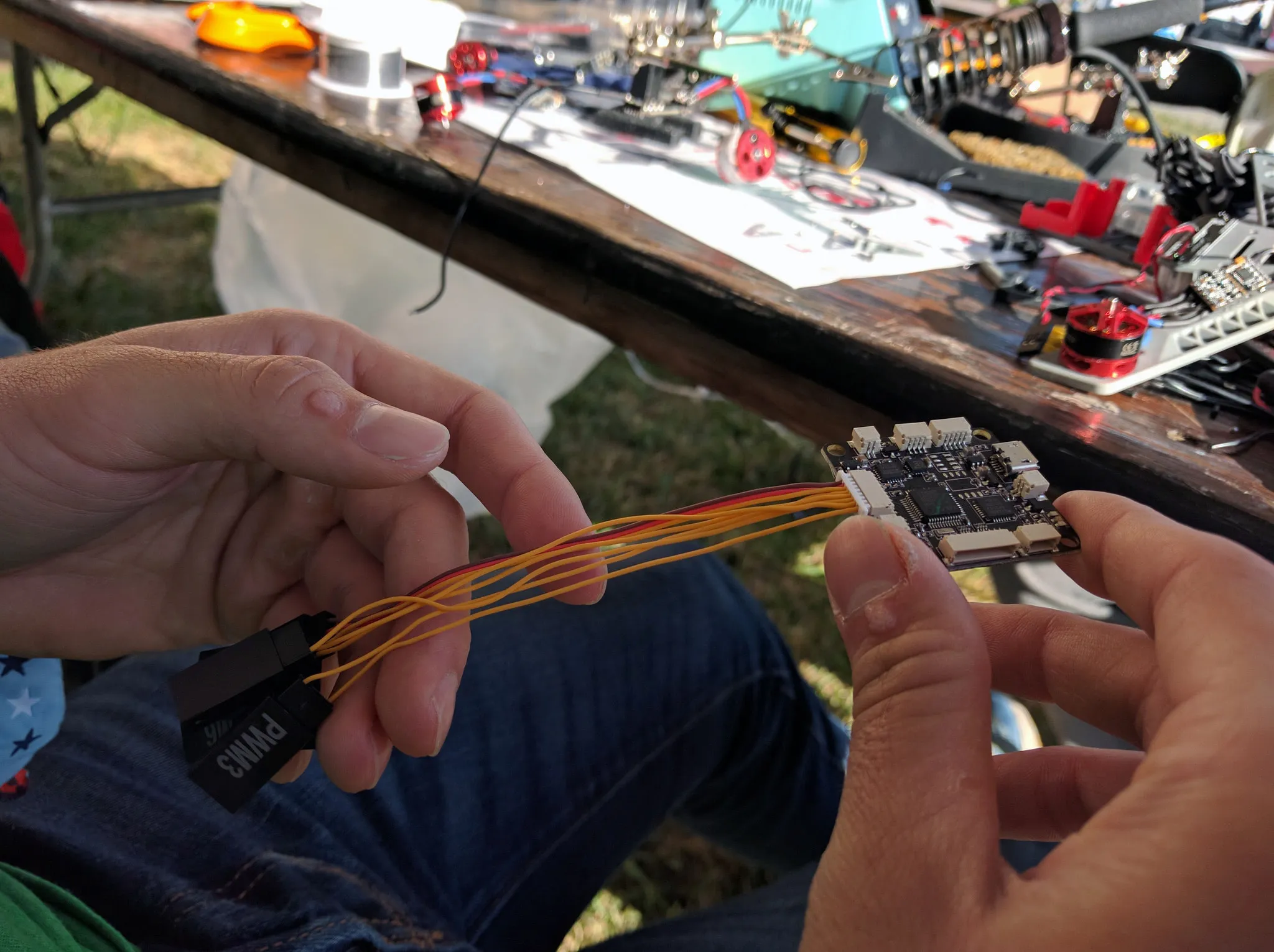
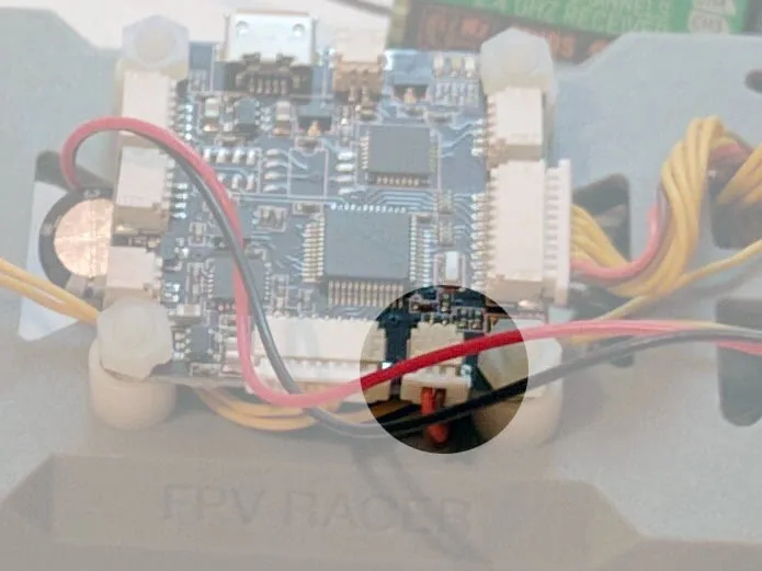
Much later in the day, we got around to connecting the single wires from the flight controller to the ESCs like so.
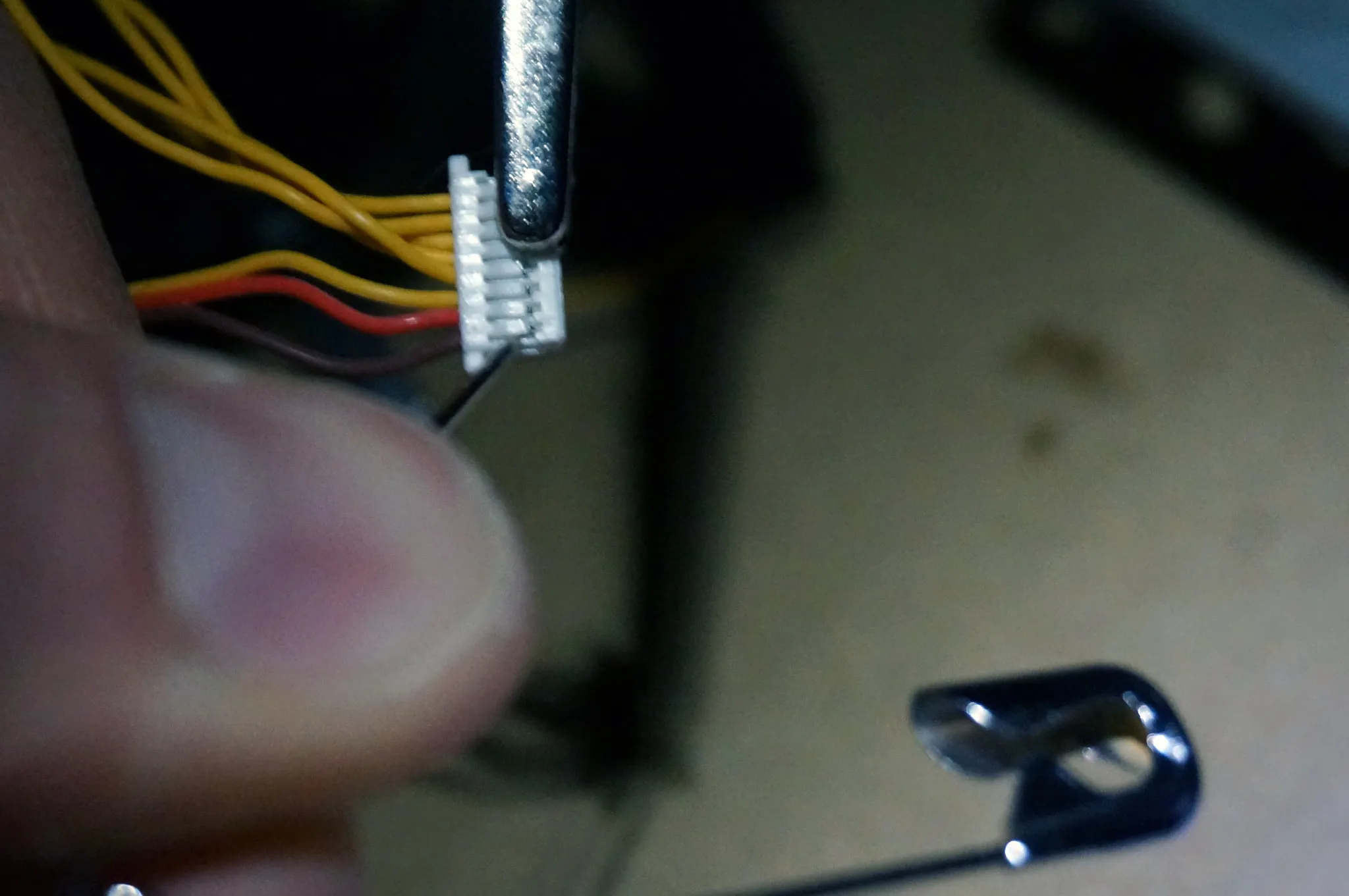
Using a pin, remove the power, ground, PWM5 and PWM6 from the header that plugs into the flight controller. We won’t need these. Clip the connectors off the ends of the PWM cables and solder them to the ESC.
Optionally, you can connect the Vbat pins to the PDB. This will allow the flight controller to check the battery voltage.
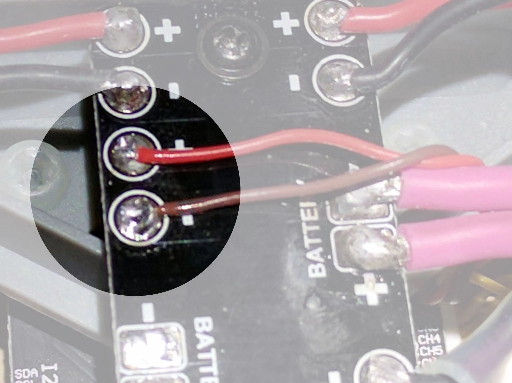
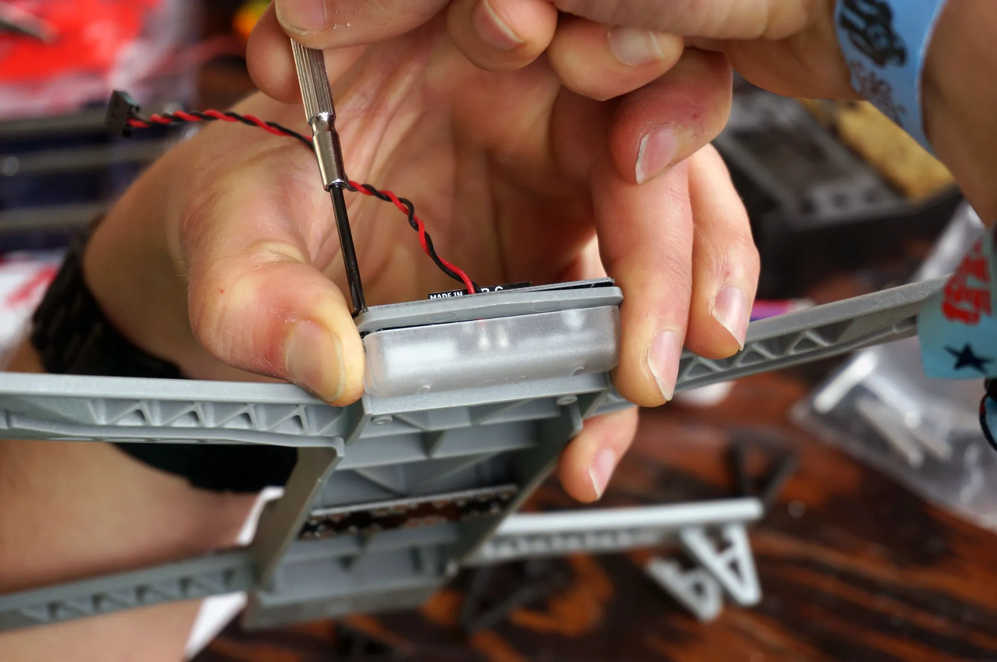
Next, get out your BEC and wire the battery side into the PDB.
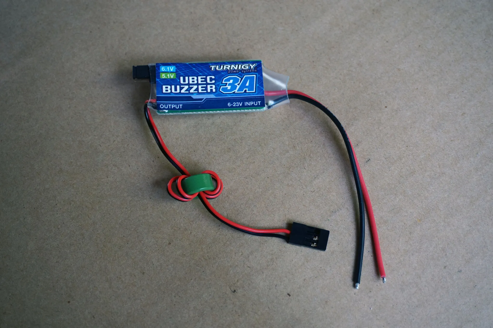
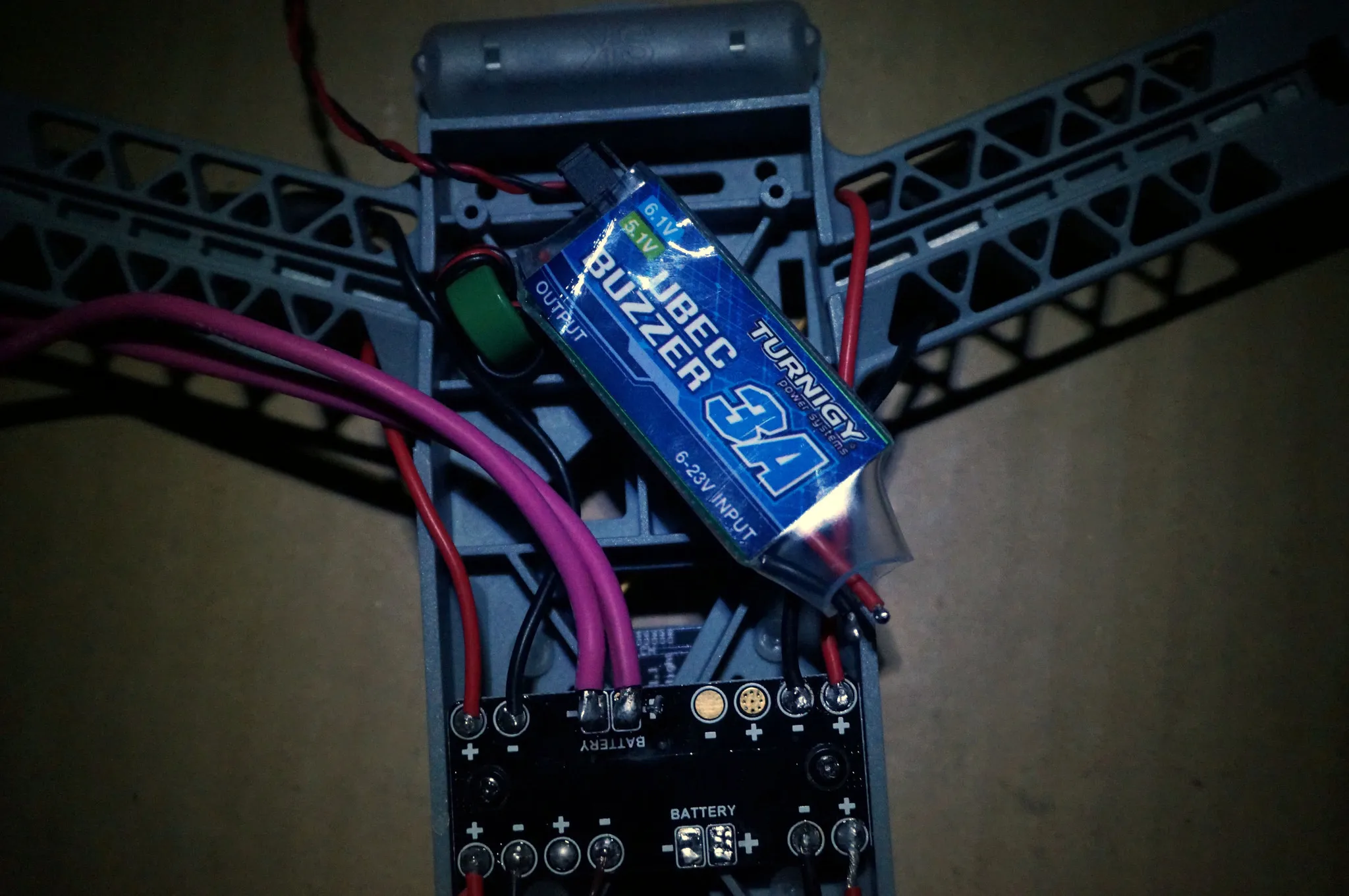
I cut the led light wires and soldered them straight onto the output side of the BEC. Route the power cable up through the frame. This will be plugged into the receiver.
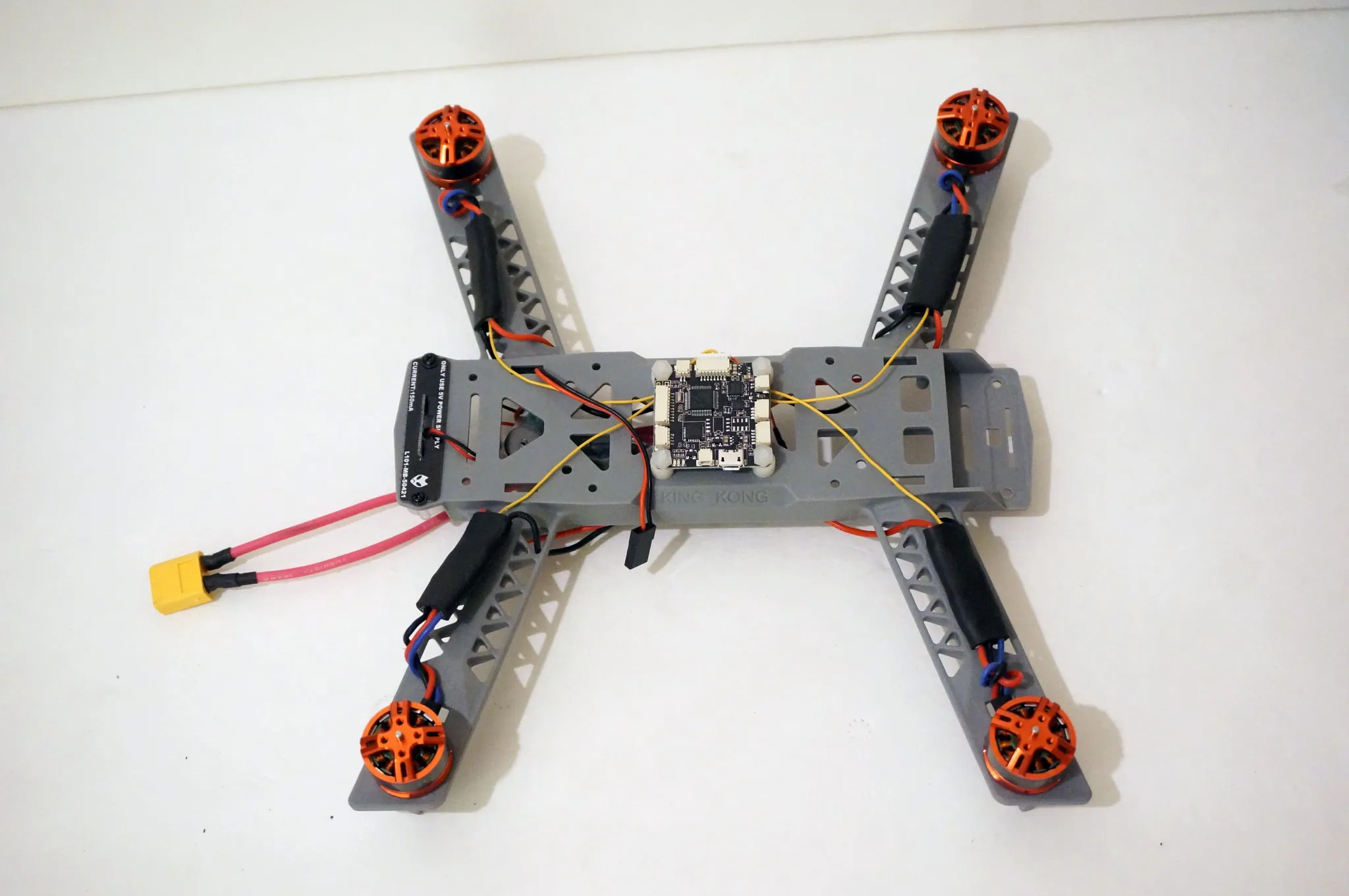
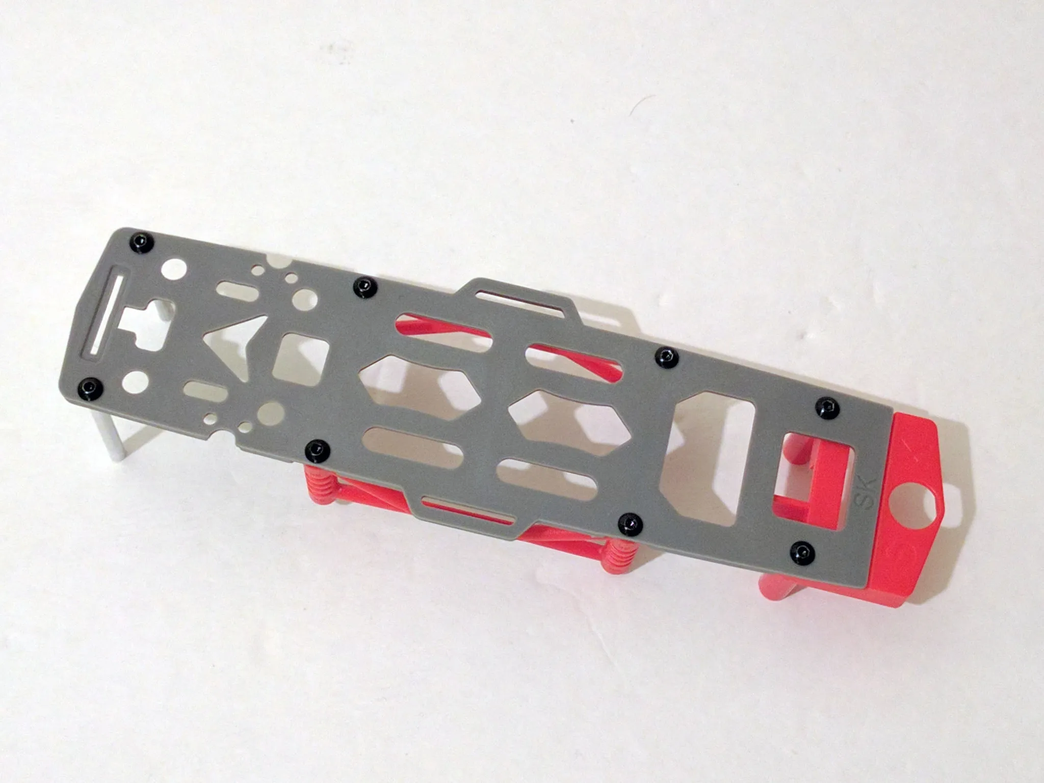
Now would be a good time to assemble the top part of the frame, so we can test fit it.
Reciever
Using the cable included with the flight controller, plug in the receiver.
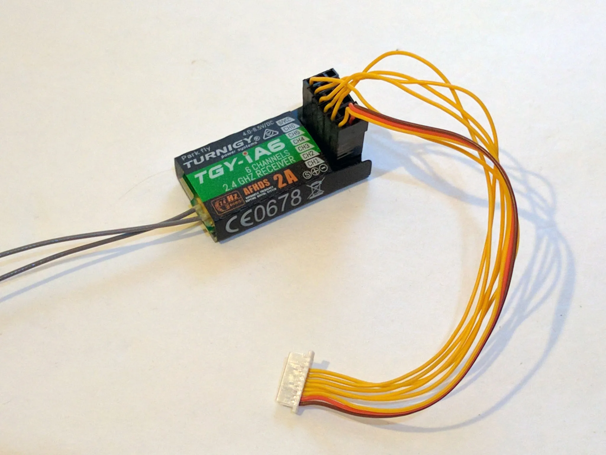
Plug the power wire from the BEC into the receiver and position the receiver.
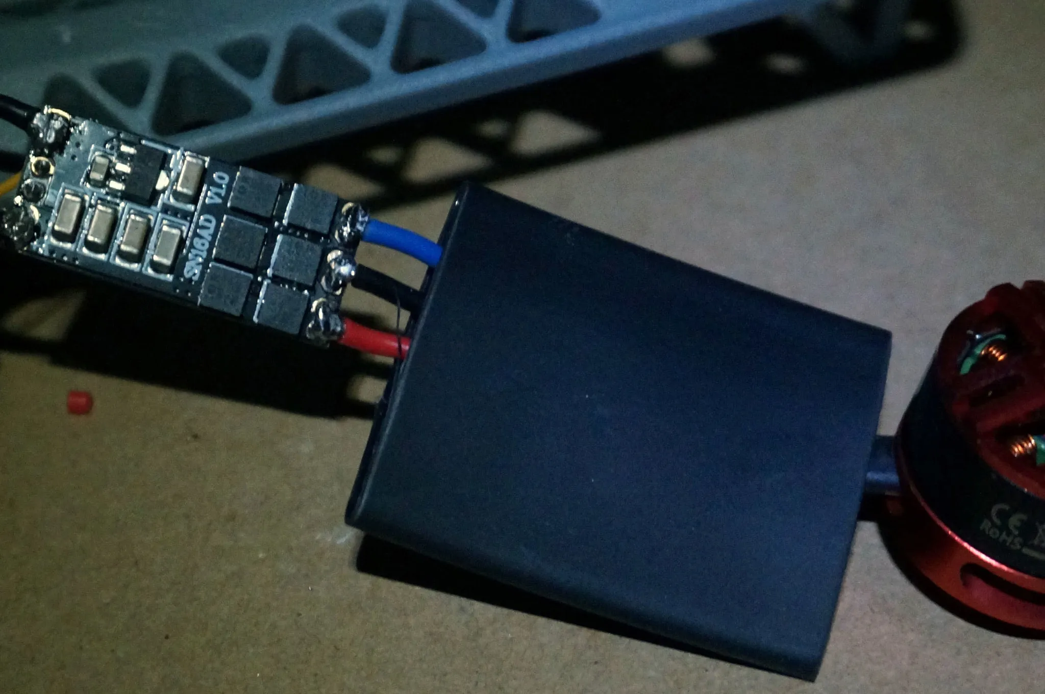
Video system
Let’s get out the video transmitter.
This camera has the SONY Effio chip, which should give it a very nice wide dynamic range. I’m really excited to see how this camera will perform.
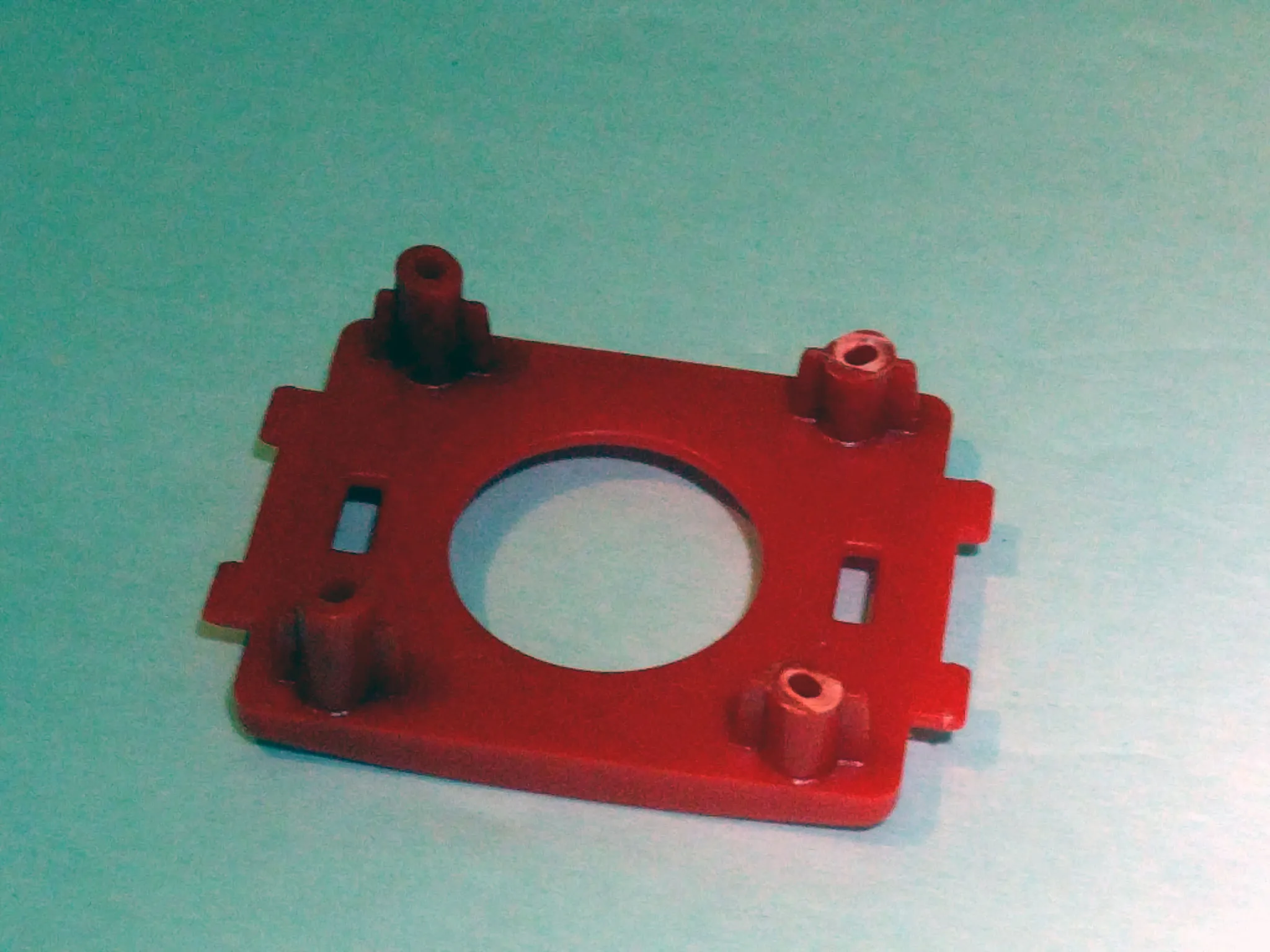
Attach the camera plate to the camera. I followed the directions in the manual and trimmed the bottom posts by about 2cm to get a little bit of up-tilt.
The camera doesn’t actually rest against these posts, so it is possible to get a large amount of up-tilt by adjusting the top and bottom screws.
The text on the front of the camera is the top.
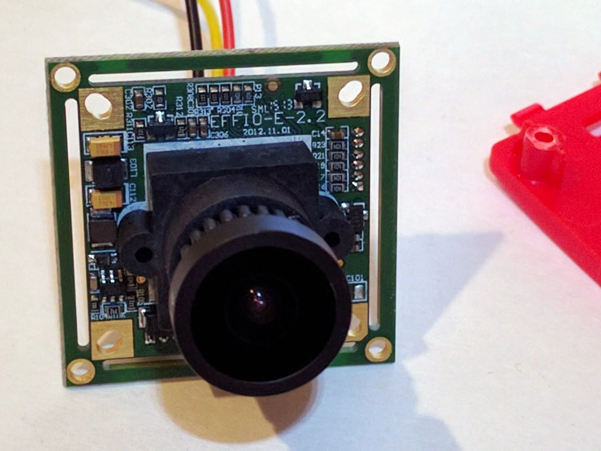
Use the pointy screws to install the camera.
Grab the video transmitter.
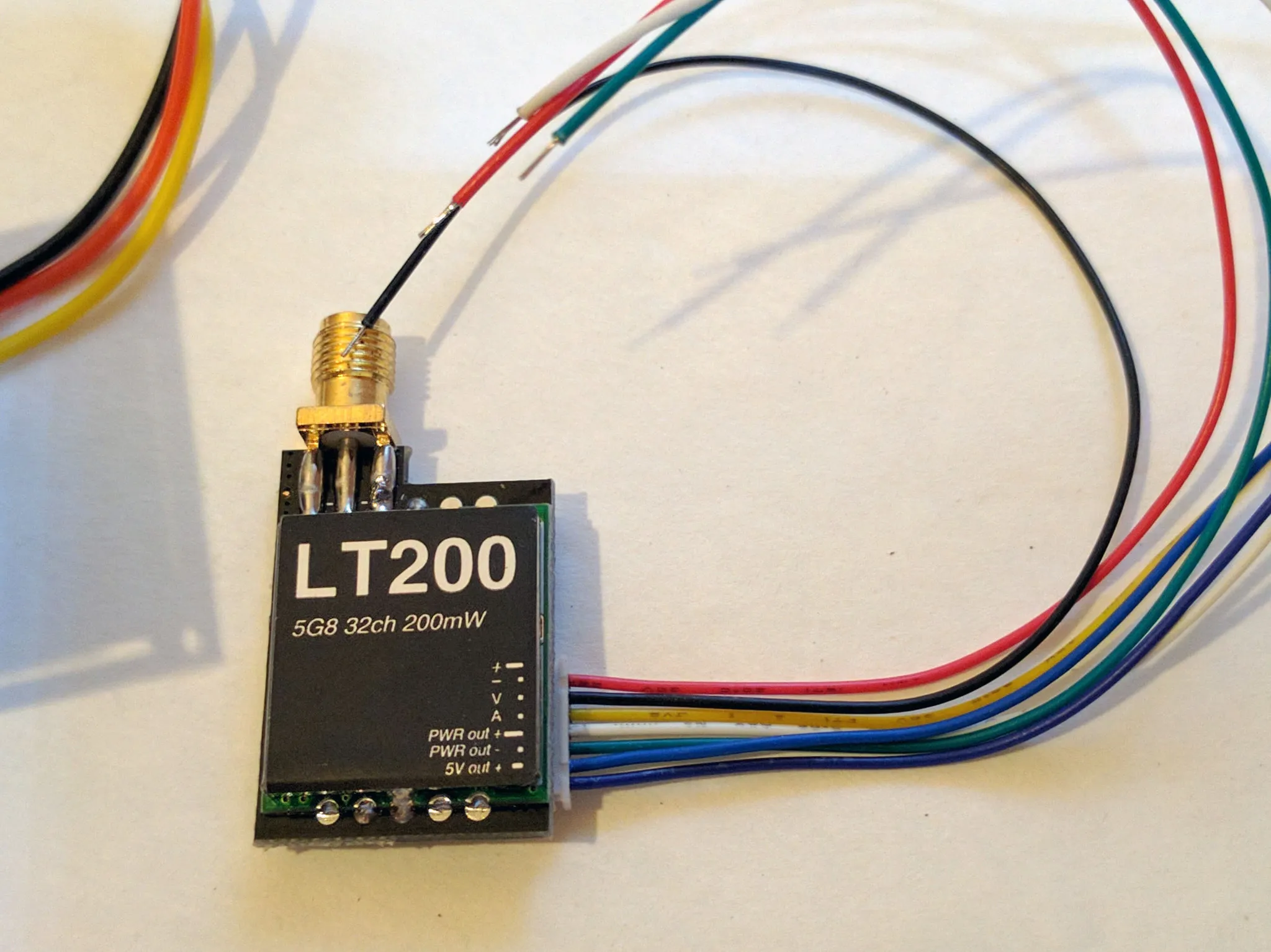
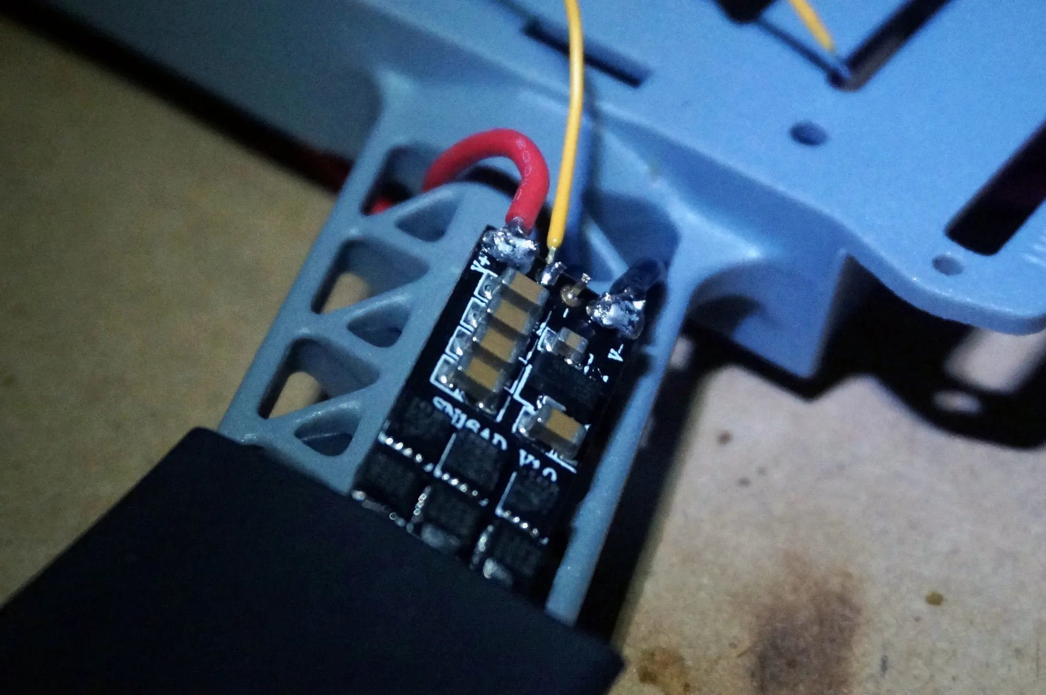
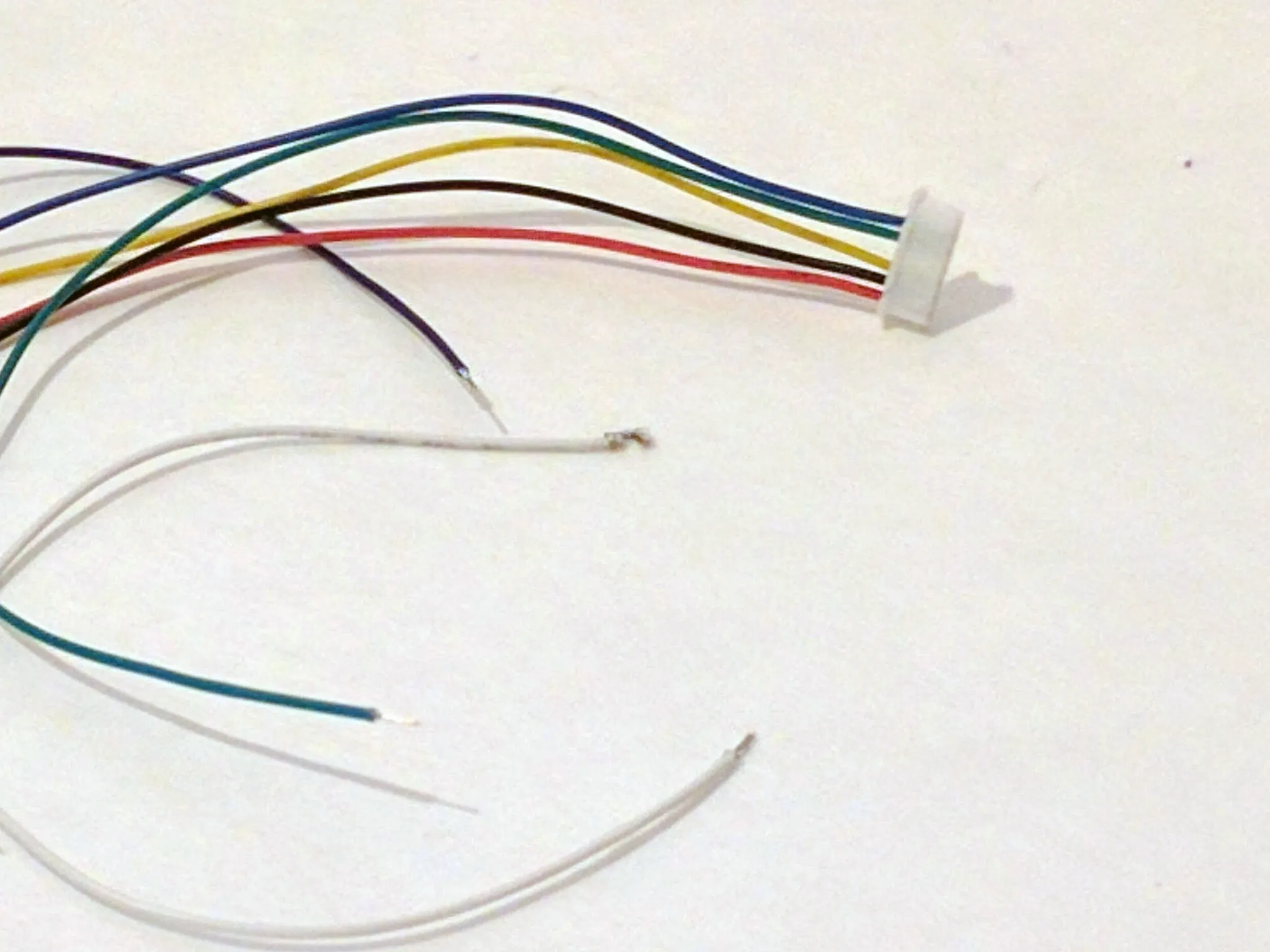
Using the pin technique, remove the unused wires from the video transmitter: audio (white) and 5v out (purple).
Solder the red and black wires from the video transmitter plug to + and - on the PDB. I also soldered on a capacitor to decrease noise. Any capacitor around 470uF, that can handle 25v+ will work well. I used a 330uf 50v capacitor.
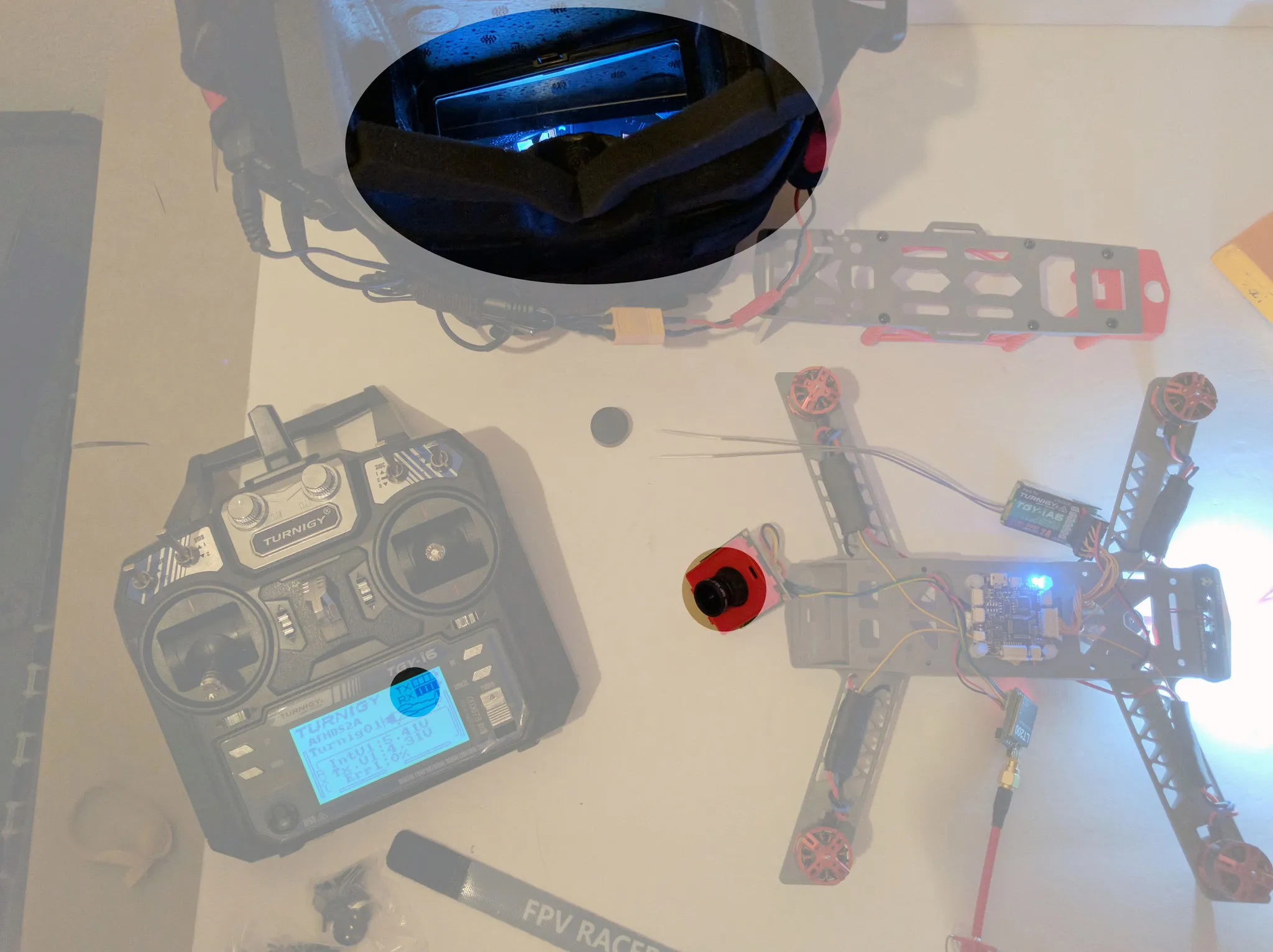
Now would be a good time to pause and test your setup. I assume you’ve already built your goggles. If not, follow
Things to check are:
-
Receiver is bound
- You should see an ‘RX’ symbol with a battery on the top right corner of the transmitter screen.
-
Video is working
- Do you see a picture in the goggles? If not, double check the wiring on your camera and video transmitter.
-
Camera is focused
- You can adjust the focus by unscrewing the lens slightly and loosening the ring on the threads. Adjust to the proper position using your goggles to check the sharpness of an object across the room. Re-tighten the ring when done.
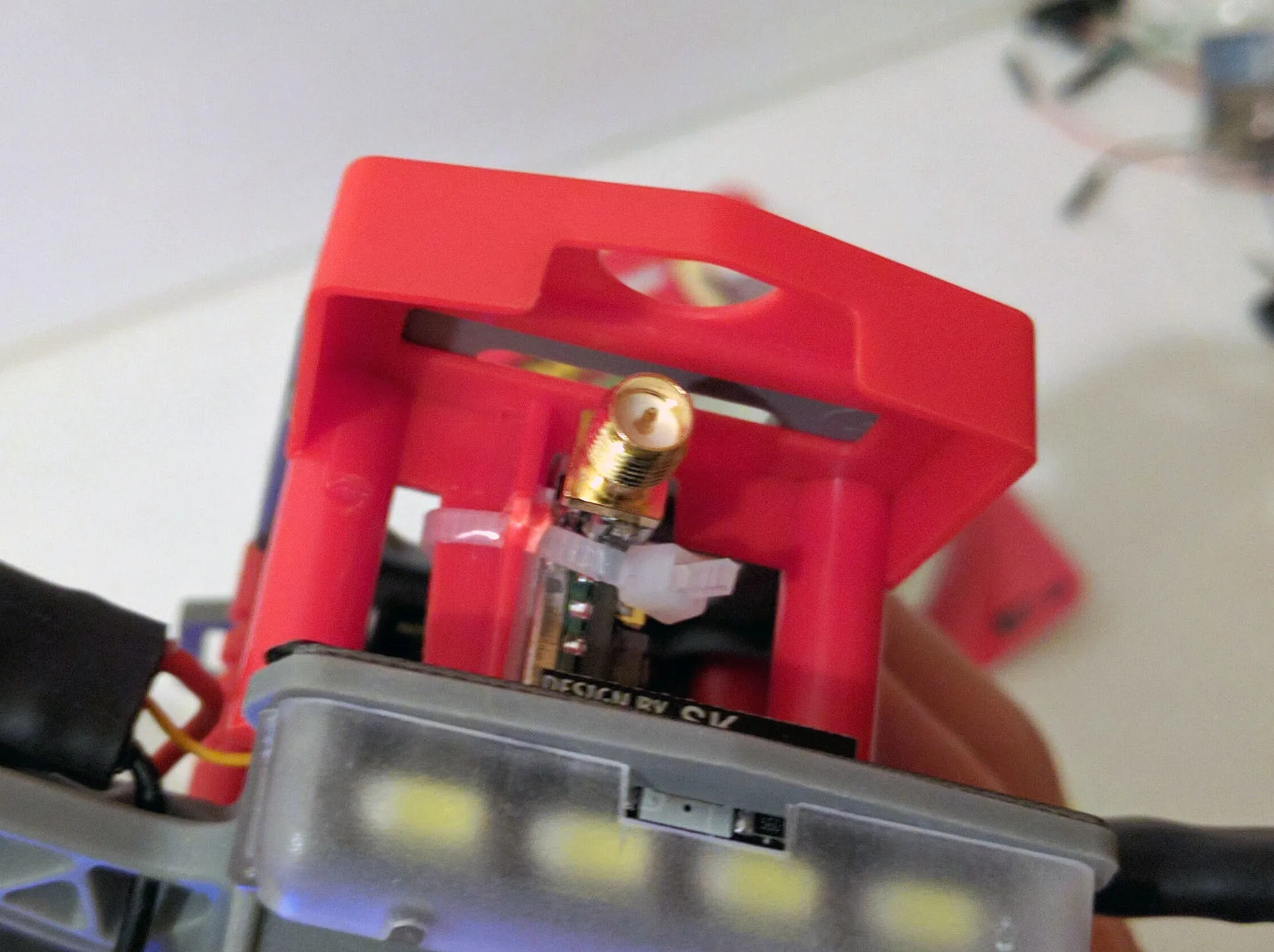
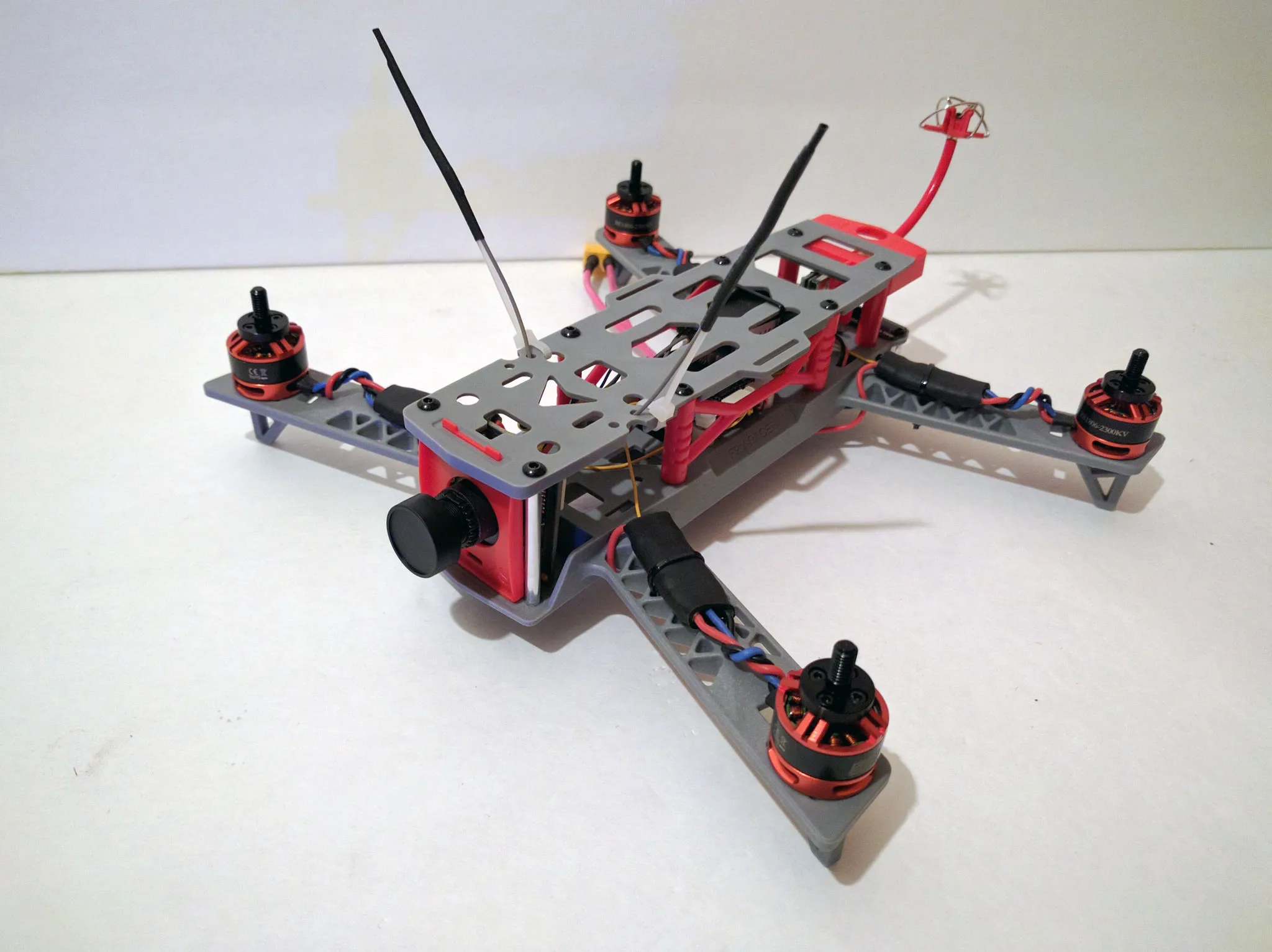
When all those things are good, we can attach the VTX to the main body of the quad copter. First, I drilled a little hole here.
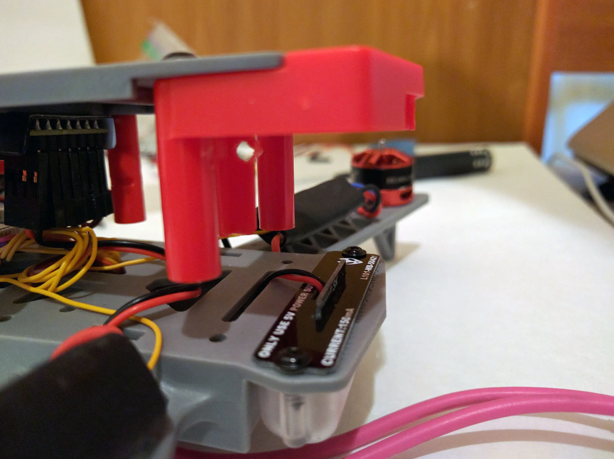
Then I peeled the sticker off of the VTX and used some double sided tape to mount the transmitter on the weird vertical plate on the back of the frame.
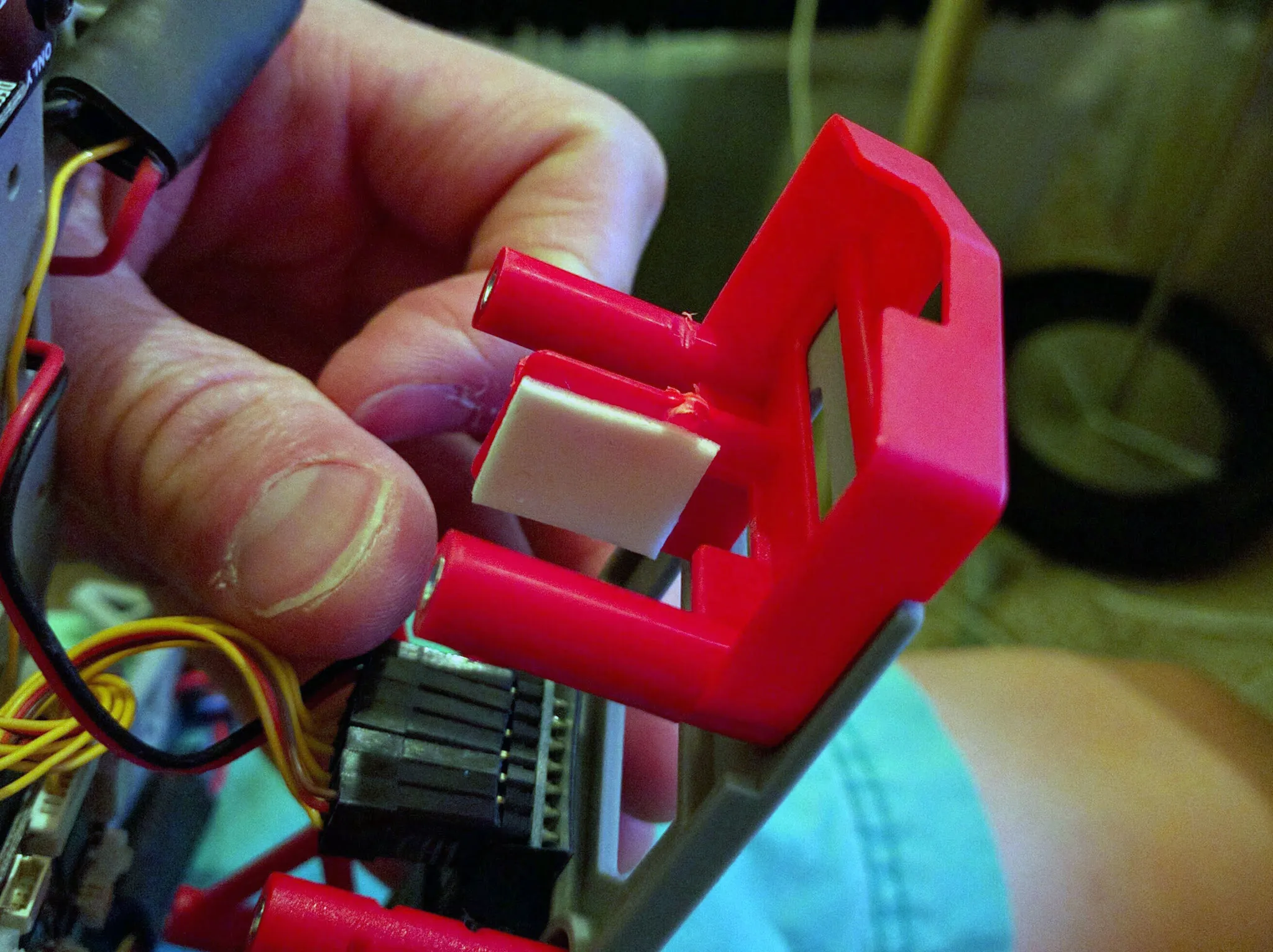
Then I zip tied it on.
Zip tie down the receiver, BEC and ESCs.
Install the prop adapters onto the motors using the shorter screws included with the motors and some blue thread locker.
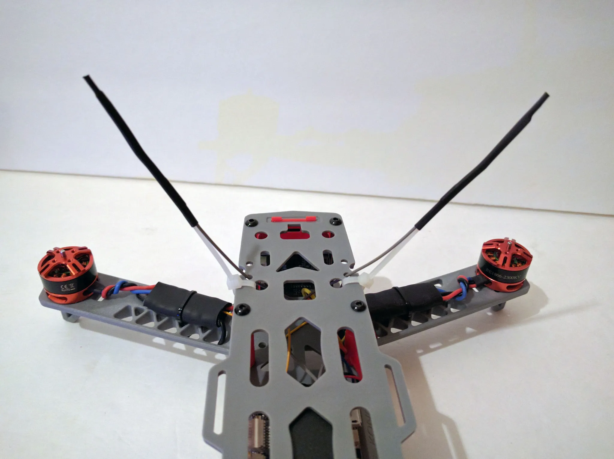
The kit includes an antenna standoff thing, but I prefer to use two zip ties and some heatshrink.
Awesome, done!
BetaFlight
Now we can update the firmware. You have 3 options for firmware: BetaFlight, CleanFlight and iNav. I always use BetaFlight, since it is the best flying firmware available.
If you don’t have Google Chrome, install that then download the BetaFlight configurator Chrome app
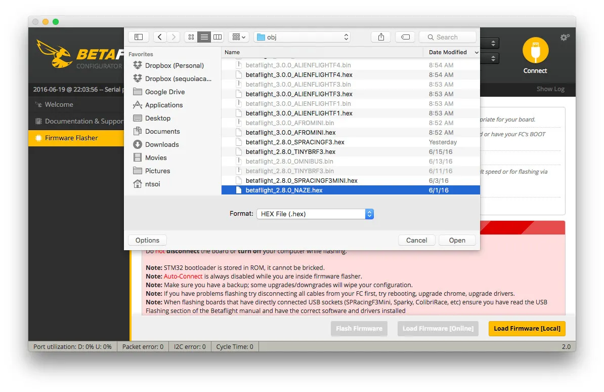
Head over to the BetaFlight Releases page and download the latest NAZE hex file.
Plug in the flight controller to your computer with a USB cable, then go to the firmware flashing tab.
Pick the latest BetaFlight release and click flash.
When it’s done, hit connect.
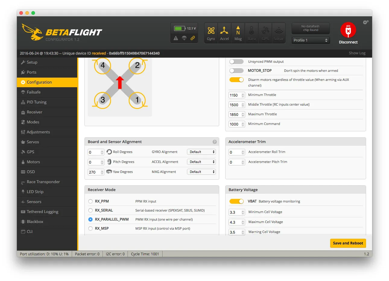
First setting to change is the board orientation on the Configuration tab. Change Yaw Degrees to 270, since we mounted the USB plug on the side of the quadcopter.
Once this is set, go back to the Setup tab and move the quadcopter around. Verify that as you move the quadcopter, the image matches the direction you’re moving the quadcopter.
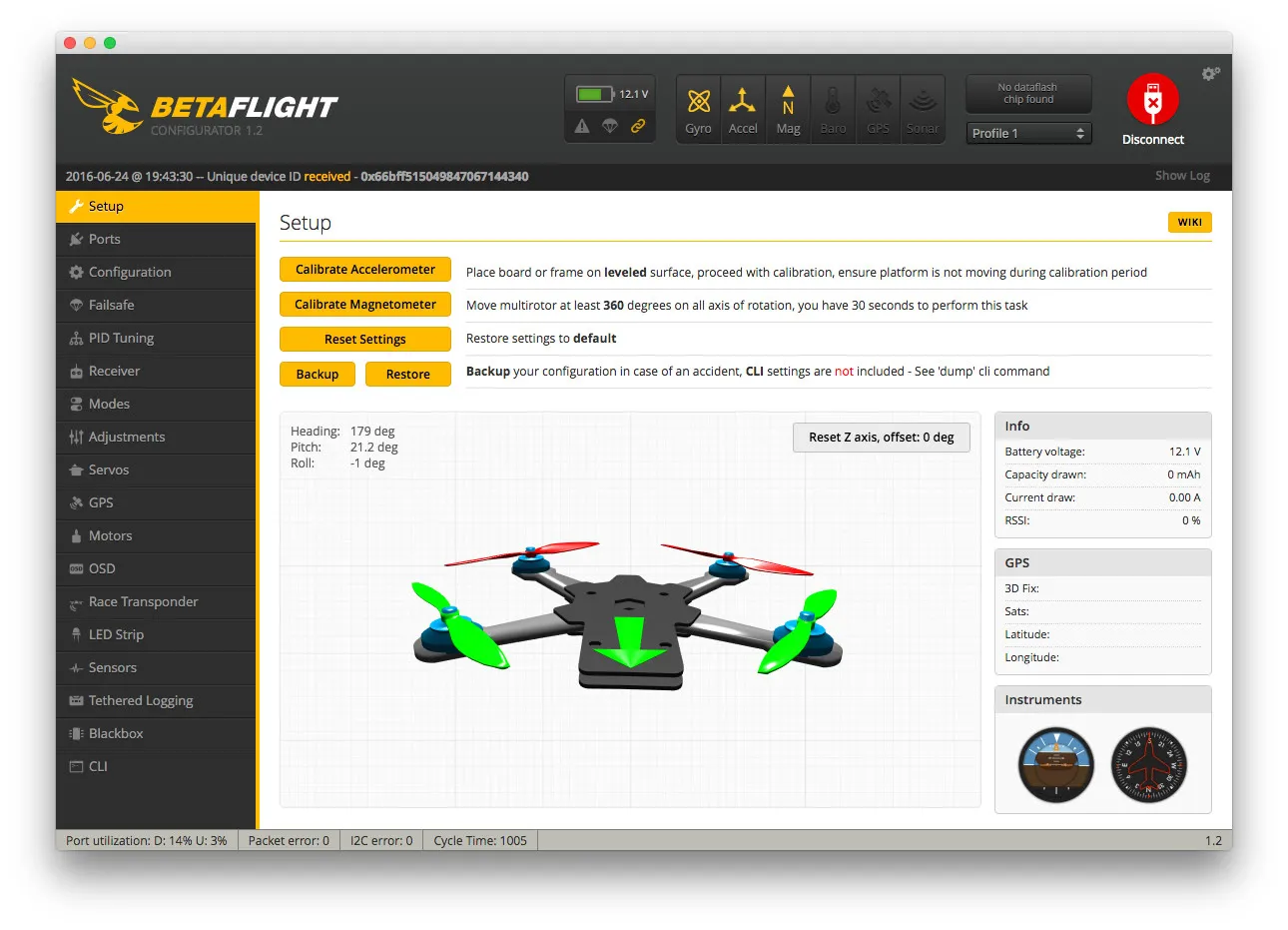
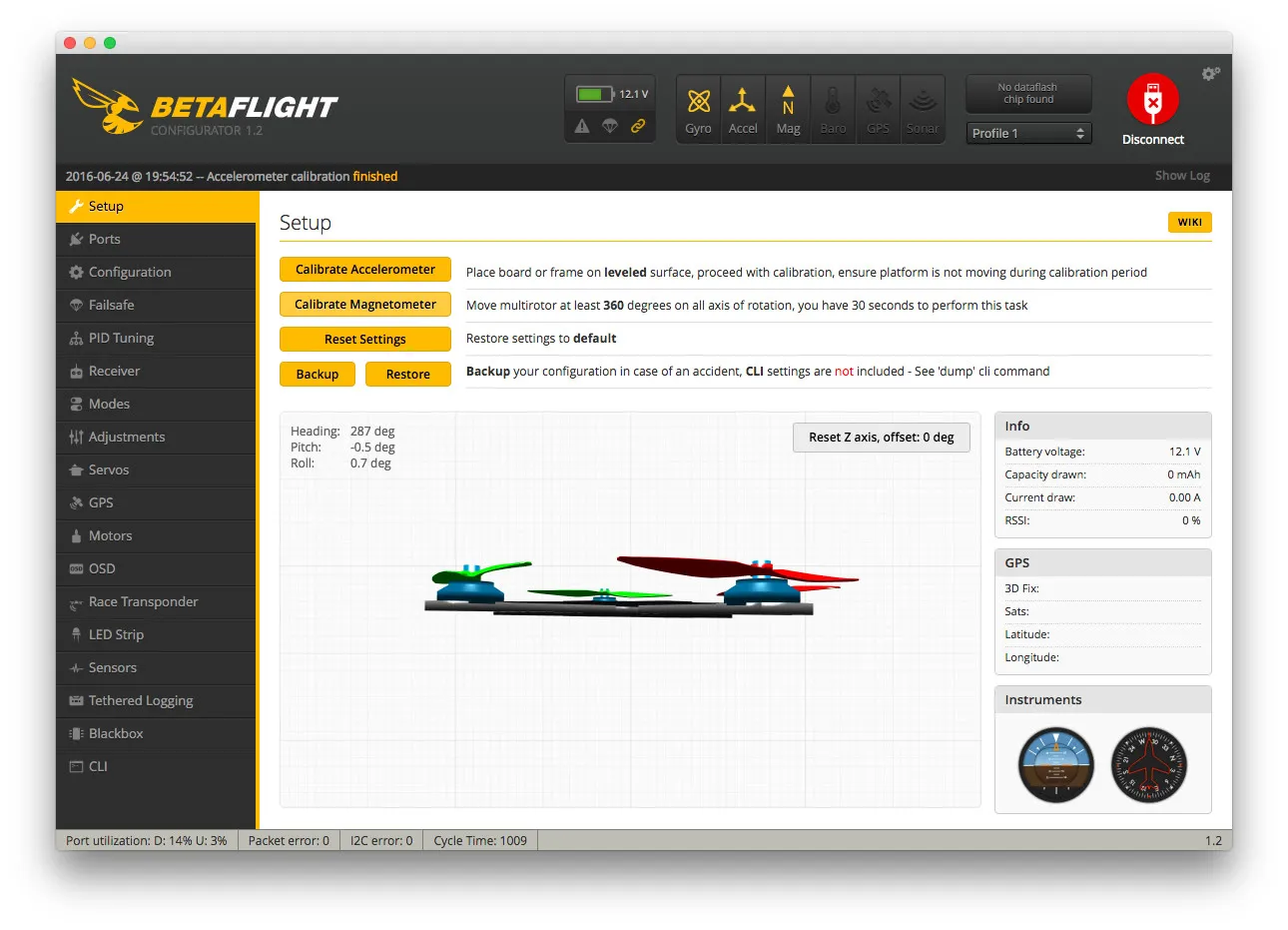
Now take the quadcopter to a hard flat surface, like the floor, and under the setup tab, click Calibrate Accelerometer. When that is done, click Calibrate Magnometer.
During Accelerometer calibration the quadcopter should be as still as possible.
During Magnometer calibration, the multirotor should be rotated 360 degrees on each axis. This does not need to be precise, but should be done away from any magnetic fields.
Radio setup
We’ll use a switch to arm and change the flight mode, so you’ll want to configure the AUX channels on your radio like so:
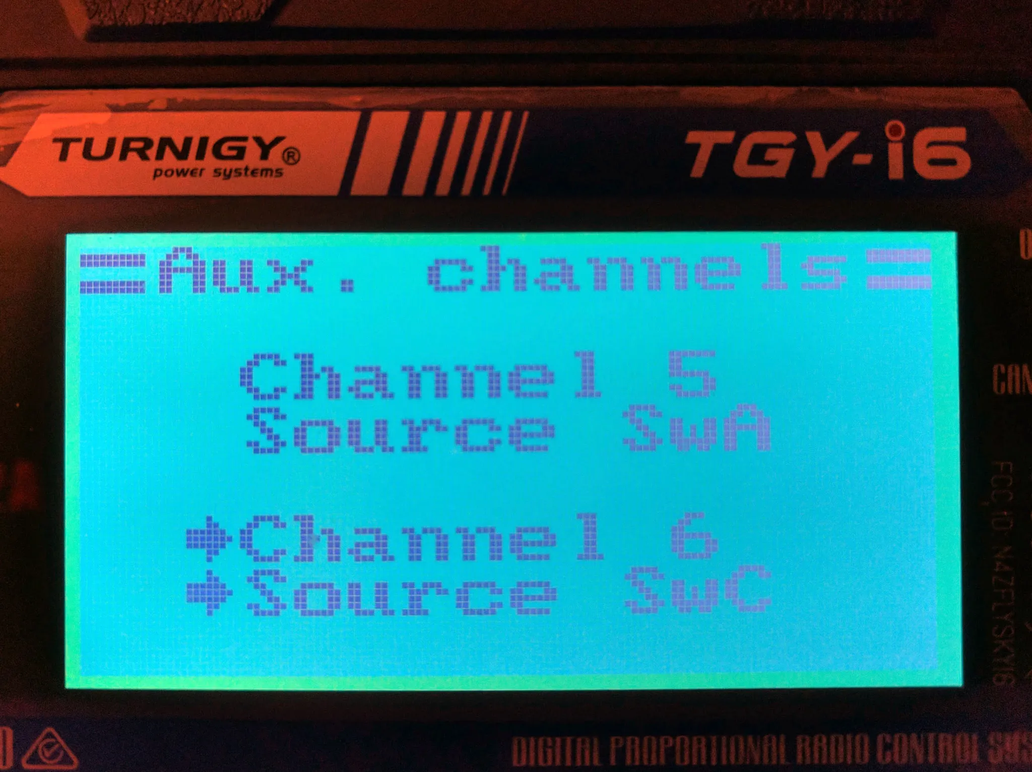
To save, press and hold the CANCEL button. This is not intuitive.
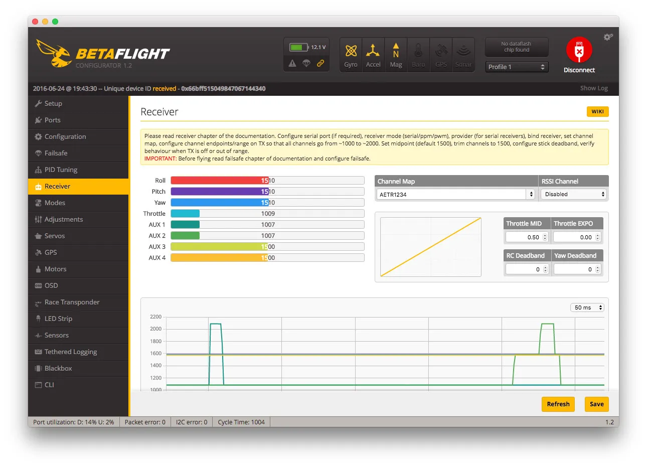
You can confirm it’s working on the Receiver screen. When you flip the switch on the left, AUX1 should change values and when you move the 3 position switch on the right, AUX2 should change values. You’ll need to plug in a battery to the quadcopter to power the receiver.
Then switch to the Modes tab and set it up like this:
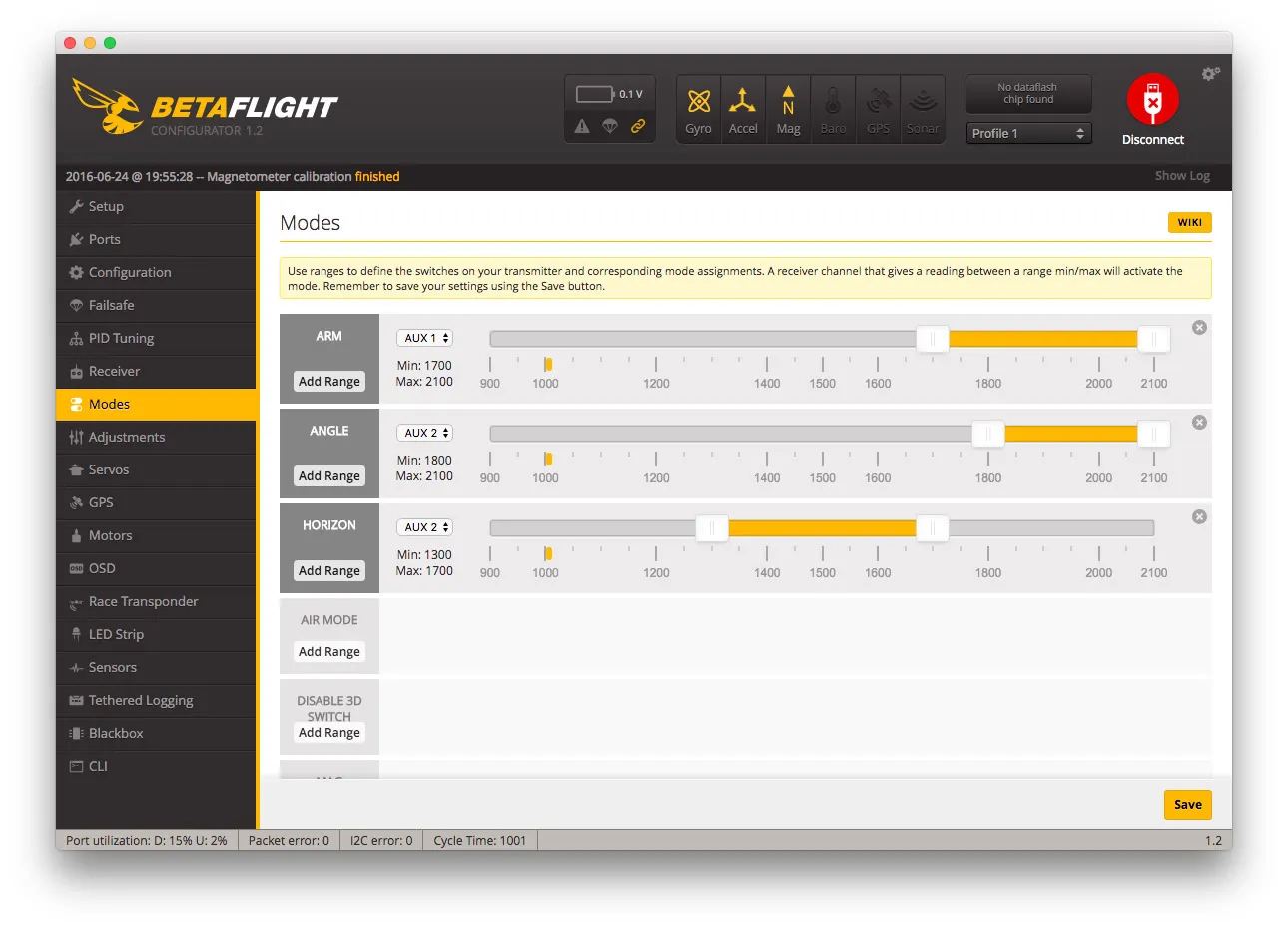
This means that the left switch will arm and disarm the quad. If you flip the left switch while flying, the motors will turn off, so don’t do that!
The 3 position switch on the right will control flight mode. All the way up is “Acro” mode, which will not auto-level. Middle is “Angle” mode which will auto level but still let you do flips. Down is “Horizon” mode, which will auto level and not let you do flips.
Failsafe
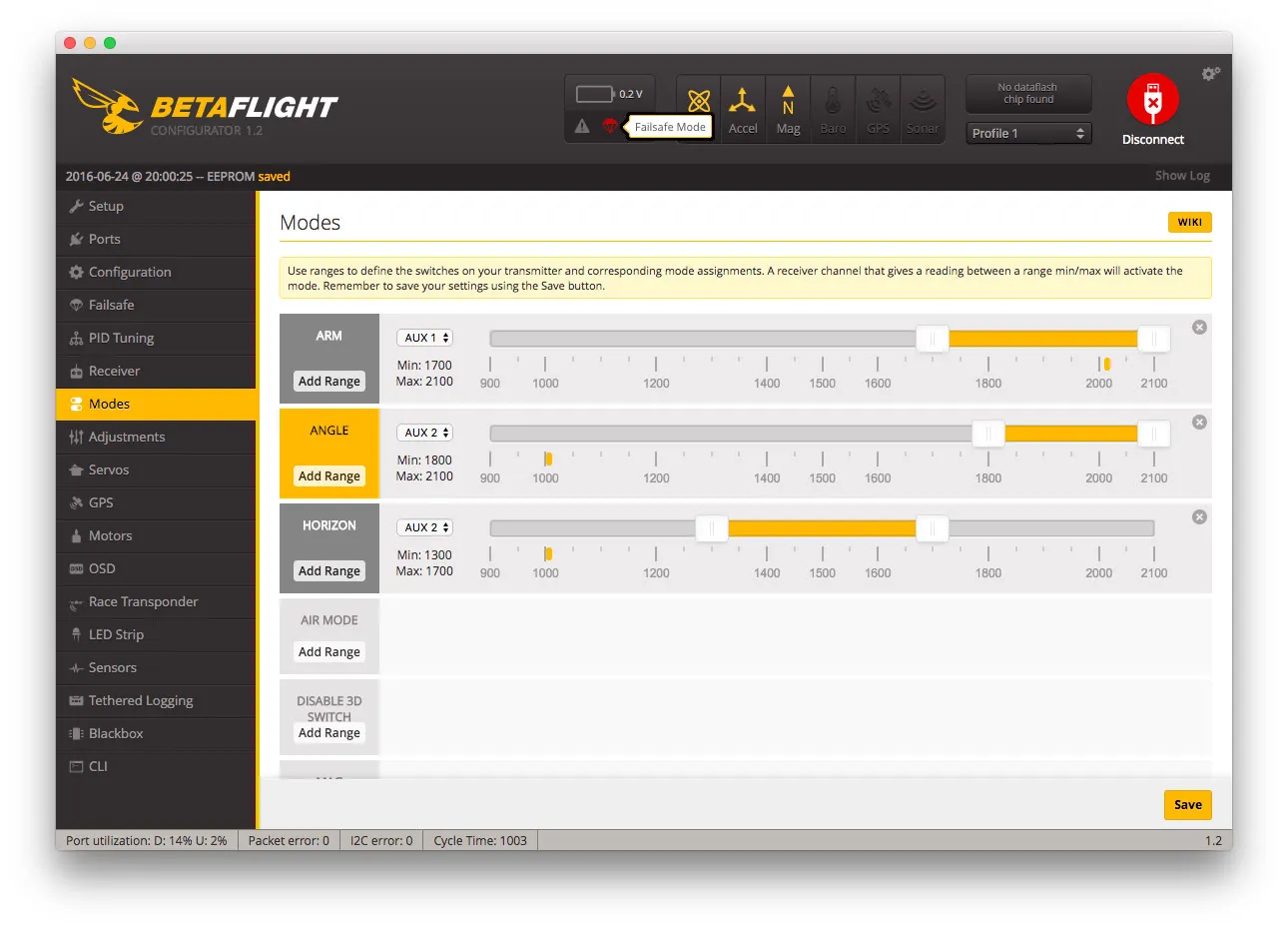
You should not have had props on this entire time, but if they’re on, remove them now. With props off, test the failsafe by:
- plugging in a battery
- arming the quad with the left switch (flip it down) on the radio
- the motors will start spinning
- throttle up a bit
- turn off the radio
The motors should then slow down for a few seconds then turn off.
You’ll also see this red parachute in the configuration tool.
Now that you’ve tested the fail safe, we can go test-hover!
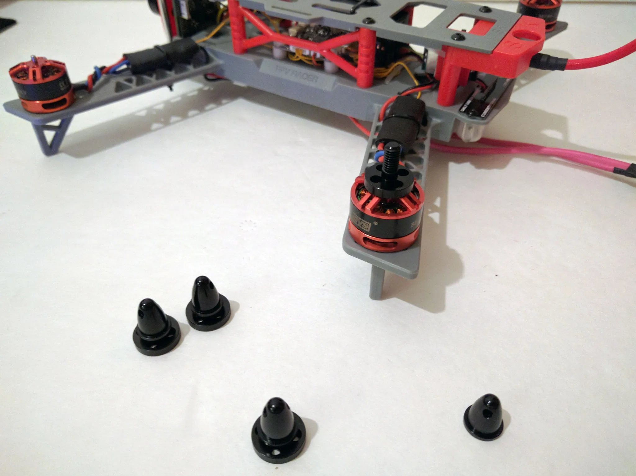
Install some propellers. I also picked up some 5mm lock nuts from the local hardware store. If you use the included prop spinners instead, be sure to use threadlock to secure them!
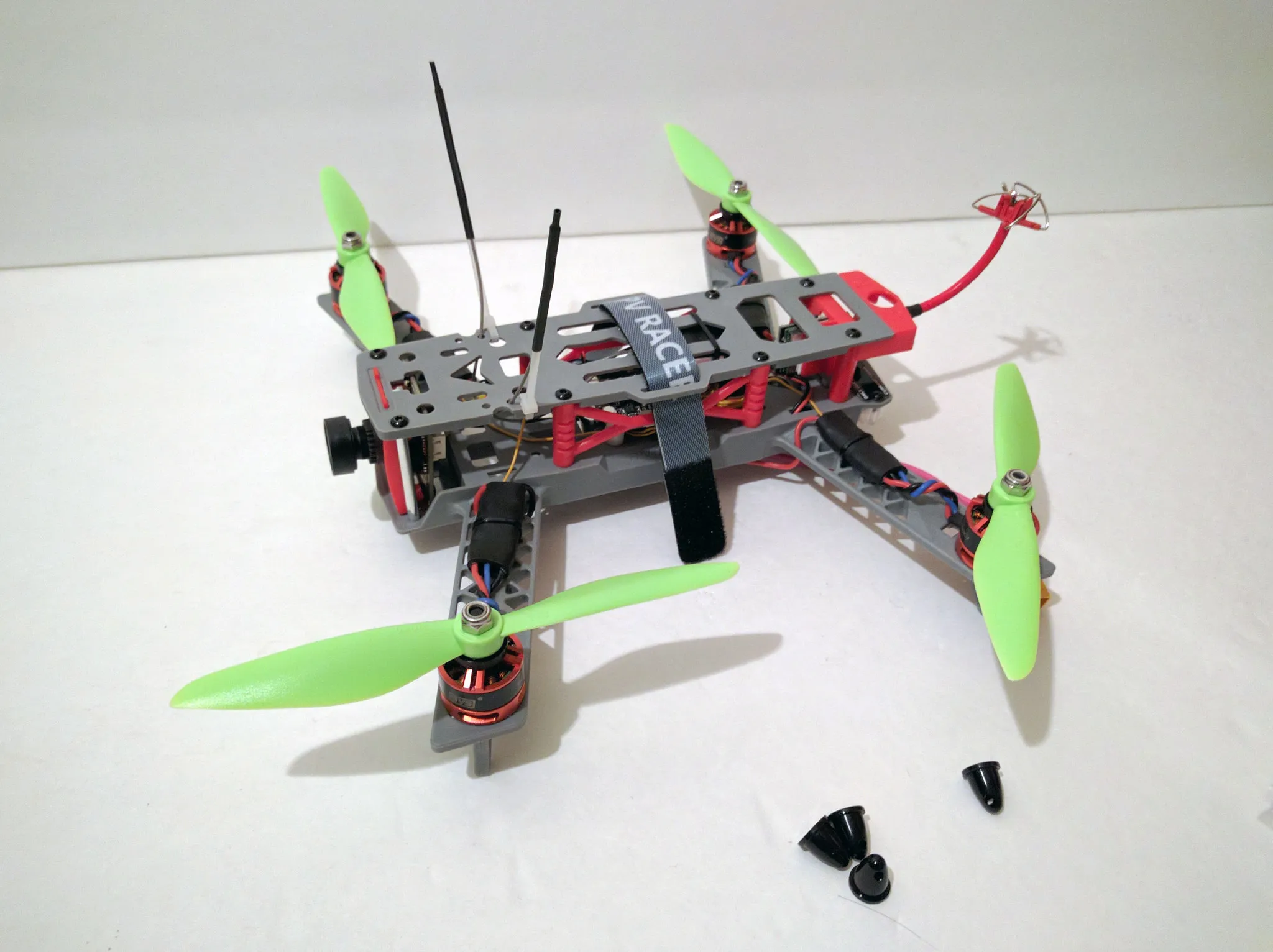
Note that these motors can handle 6” props, but this will be pushing their limit. If you want to be on the safe side, use some 5” props instead.
Time to go fly!